1
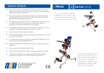
INSTALLATION and USER MANUAL EDITION 6 —— April 2014 INTRODUCTION RMS Ltd would like to take this opportunity of thanking you for choosing a GILL III Modular Adjustable System. We are confident that it will meet with the necessary seating requirements of the user for which it was prescribed. From the time of its initial conception, the GILL III System has undergone rigorous strength testing and quality inspections, including successful “Crash Testing” to ISO 16840-4 standards, at the Millbrook Proving Ground on June 1st 2005. Our thanks go to Messrs. Q-Straint for supplying the restraint systems to enable the test to be successfully carried out. (also see Page 16). In view of the wide range of wheelchairs into which the GILL III Modular Adjustable Seating System can be interfaced, the pictures in this manual may not depict identically the components supplied, or the location positions of installation for your application. They are intended however, for general guidance purposes only and to assist a suitably qualified person to install and adjust a complete GILL III System. RMS Ltd reserves the right to change, without notice, the design, methods of manufacture, or any materials used in the construction of the GILL III System, where it considers such changes will serve to improve the product quality, or become necessary to meet any changes in device legislation. Should the reader have any concerns regarding the installation, set-up, adjustment, or use of the GILL III System, please contact the RMS Ltd. Technical Help-Line on 01795-477280. CONTENTS Introduction Safety Guidelines Initial Installation:Seat Base Backrest Pelvic Supports Thoracic Supports Headrest Kneeblocks and Pommels Sacral Pad Upholstery Transportation Additional information regarding Transportation Warranty Statement Product Maintenance Page 2 Page 2 3 4 5 7 9 10 11 12 15 16 18 19 22 23 SAFETY GUIDELINES Due to the various activities that a wheelchair user has to perform, RMS recommends that, prior to issuing the GILL III System, and the wheelchair into which it is to be interfaced, this manual, together with any wheelchair manufacturer’ User Guide, should be studied by all relevant persons to ensure that all instructions, procedures and warnings are carefully observed and understood. For correct support and user comfort, it is strongly recommended that the initial installation and adjustments are carried out by a suitably qualified person. The maximum occupant capacity of a complete GILL III System for transportation purposes, when interfaced into a wheelchair with a seat width up to 17”, is 54Kg (8.5 stones). As the installation of a GILL III System may raise or position the user further forward in their wheelchair, an appropriate stability test should be carried out prior to final commissioning. After the GILL III System has been initially adjusted to suit the individual user, any settings should not be subsequently affected by the removal and refitting of the Seat Base or Backrest to allow the wheelchair to be folded. However, care should be taken not to impact adjustable components whilst the Seat Base or Backrest is removed from the wheelchair as this could affect their original pre-set position. To accommodate any changes in user growth or postural positioning, it is recommended that the user be checked at regular intervals by a suitably qualified person, to ensure that adjustable components are correctly set to suit the user’s current requirements. Carers should ensure correct utilisation of any positioning Straps or Harnesses, as failure to do so could result in injury to the user. It is recommended that any postural Straps or Harnesses being used, are the first items to be secured when the user enters the seat and the last items to be released before exiting. Worn or damaged upholstery can lead to hygiene contamination, cause injury to the user and, in some cases, fail to support the user correctly. Regular inspections of all upholstery should be made and any defects should be reported to the relevant authority for rectification as soon as possible. Ancillary devices, such as the Headrest, positioning Straps and Harnesses, Kneeblock or Pommel should be checked for security on a daily basis. The wheelchair parking brakes should always be applied before attempting to transfer the occupant, removing or refitting the GILL III System or making any adjustments. Never hang heavy objects on the GILL III System or any part of the wheelchair, as this could seriously affect the overall stability. Page 3 The GILL III Seating System — Component Identification Angle and Depth adjustable Backrest Mountings using the RMS Quick-Release Lock and Latch System Multi-adjustable Headrest RMS positive-locking “Swing-Away” Thoracic Supports with optional Fixed style available Backrest Panel with Padded Cushion Multi-adjustable Kneeblock or Pommel available With Ratchet or “Pop-Pin” Mounting Optional Fixed or “Swing-Away style Pelvic Supports Seat Base interface using RMS Quick-Release Lock and Latch System Seat Base Panel with Flat or Ramped Cushion INITIAL INSTALLATION IMPORTANT NOTE: The Gill III Modular Seating System is supplied assembled and ready to be interfaced onto the intended surrogate wheelchair. However, the installer should note that some adjustment of both Seat and Backrest Support Brackets may be necessary to ensure correct interfacing. The installer should also note that at the time of despatch from the factory, none of the Backrest or Seat Base Support Brackets has been fully and finally secured. This has been done to allow the installer ease of correctly positioning the interface brackets to suit the intended surrogate base. It is therefore, the responsibility of the installer to ensure that all Interface Screws and Domed Nylock Nuts are correctly tightened, before handover to the user. (This does not apply to Gill III Seat Units fitted into a surrogate base at the RMS factory) TOOLS REQUIRED:- Hexagon Keys - 3mm, 4mm & 5mm. Spanner 13mm Flat Bladed Screwdriver (Medium) Page 4 NOTES: 1. To install either the full GILL III System, or just a Seat Base or Backrest, it will be necessary to remove the relevant wheelchair seat canvases. 2. Before commencing installation, the wheelchair should be placed on a suitable level non-slip surface, with both parking brakes applied. For ease of installation, both sidearms should be removed, wherever possible. 3. Any references to left or right, relate to positions as viewed from being seated in the wheelchair. 4. It will not necessary to apply Loctite thread-lock or equivalent to any screws or nuts used on this seating system. Fig.1 SEAT BASE INSTALLATION Disconnect and remove the seat canvas from the surrogate wheelchair. (Methods may vary according to make and model of wheelchair). a Temporarily place the GILL III Seat Base in its intended position on the wheelchair seat canvas rails, ensuring there is sufficient clearance around any cross braces and that the Seat Support Brackets (a Fig.1) do not foul any seat rail support saddles. NOTE: In the event of Seat Support Brackets fouling seat rail saddles, or the Seat Base Panel fouling a cross brace, alternative mounting positions for the Support Brackets are available on the Seat Base Panel, at 25mm centres forward or rearward of their factory fitted position (see Fig.1). Should it be necessary to adjust or move the Seat Support Brackets, the installer will find removal of the Velcro attached Seat Cushion allows better access to the M6 Hex. Drive Countersunk Screws attaching the Mounting Brackets to the Seat Base Panel. The Brackets are secured in position by means of special key-way Nuts with Domed Nylock lock-nuts and care should be taken to ensure the keyway Nuts are located correctly in the Bracket slots when tightening the bracket securing screws. The Seat Support Bracket hooks should then sit snugly over the wheelchair seat rails with the correct bracket width and positioning achieved. NOTE: If threaded inserts (previously used by seat canvas screws) prevent the correct Support Bracket position being achieved, the insert should be removed or filed level with the rail. Ensure all screws are securely tightened after repositioning Brackets. Before removing Seat Base from wheelchair, lightly mark seat rails at back edge of rear Support Brackets and front edge of the forward Support Brackets. After removing screws and nuts from the Seat Base Lock and Latch Brackets (b and c Fig. 2) Spring open each rear Lock Bracket (b) to allow them to slide over the seat canvas rails. Locate each Lock Bracket just rearward of the previously marked rear position, (with locating lugs uppermost and pointing forward (as Fig. 2). Re-install clamping screws and tighten sufficient to maintain the Bracket position on the seat rails. [Cont] Page 5 Fig. 2 Lock Bracket b Lock Bracket b Latch Bracket c Latch shown in locked position Securing Screws Install the Seat Base Latch Brackets (c Fig. 2) over the seat canvas rails and locate against the previously marked position. Re-install clamping screws and tighten clamps just sufficient to lightly maintain their position but still allowing their movement if required. Pull each locking plunger forwards until it clicks into the unlocked position. Re-install Seat Base Panel by raising the front end to approximately 15 whilst locating the rear Support Brackets (a Fig.1) under each Lock Bracket (b Fig. 2). With the Seat Panel resting on the seat rails and pushed fully rearward, slide front Latch Brackets (c Fig.2), with the locking plunger uppermost, rearwards until they lightly contact the front Seat Support Brackets. Allow 2mm maximum clearance between Seat and Latch Brackets before fully tightening the screws sufficient to maintain the Bracket positions on the seat rails. Slide the locking plunger on each Latch Bracket, fully rearwards to locate over each front Support Bracket (Fig. 3). To confirm correct bracket positioning, it is recommended that a test removal and refit of the Seat Base Panel is carried at this stage. For ease of working, make any necessary adjustments before refitting the Velcro attached Seat Cushion. Page 6 BACKREST INSTALLATION Disconnect and remove wheelchair backrest canvas. (Methods may vary according to make and model of wheelchair). Temporarily support the GILL III Backrest in its intended position on the front face of the wheelchair backrest frame tubes. Mark the wheelchair backrest frames in line with the bottom edges of the lower Backrest Mounting Hook Brackets. NOTE: Check the wheelchair backrest frame tubes for obstacles preventing the Backrest Brackets from sitting correctly against the frames. Should it be necessary to relocate the Backrest Brackets (d & e Fig. 3), remove the M6 Domed Lock-nuts from each screw, before removing the M6 Hex.Drive Fig.3 countersunk Screws, attaching the Mounting Brackets to the Backrest Panel. (Screws are located 25mm Upper Backrest inboard from the outer edge on the Support Brackets front face of the Backrest Panel, with d alternative mounting holes available above and below at 25mm centres). Alternative Backrest Width adjustment of the Mounting Bracket mounting Brackets can also be made at these positions points. (see Figs. 6 & 7). The Brackets are secured in position by means of special “T” shaped keyway Nuts and care should be taken to Lower Brackets ensure these Nuts are located e correctly in the Bracket slots when tightening the securing screws after relocation. Tighten screws sufficient to maintain the Bracket position. With locating lugs pointing forwards and upwards centrally, install each lower Backrest Lock Bracket onto the backrest tubes with top edges of the clamps in line with the previously marked positions. Install clamping screws and tighten sufficient to maintain the Lock Bracket position. Re-install GILL III Backrest onto wheelchair with the lower Mounting Hook Brackets located against the Backrest Lock Brackets (see Fig. 5a). Check for correct contact of the Hook Brackets against the wheelchair backrest frame tubes, as angles may vary dependant on wheelchair make and model. Where the Hooks do not sit flat against the tubes, this can be adjusted by slackening screws (f Fig. 5a) on Mounting Brackets. Correctly position Hooks and re-tighten screws sufficient to maintain Bracket positions. With the Backrest resting against frame tubes, lightly mark positions of the top edges of the upper Mounting Hook Brackets. [Cont] Page 7 With their locking plungers in the raised position, install upper Latch Brackets onto frame tubes with lower edges in line with the previously marked positions. Install securing screws and tighten sufficient to maintain their position. Lock Backrest in place by sliding the Latch plungers downwards, over each Hook Bracket, until they click into their locked position (see Fig. 5). Fig. 4 Fig. 5 Latch shown in locked position Lock Bracket NOTE: To suit individual user requirements, it may be necessary to change the overall angle of the Backrest Panel, or its position in relation to the wheelchair backrest frame. Four Hook Bracket mounting positions are available on the upper Mounting Brackets, (see Fig. 6), with three positions available on the lower Mounting Brackets, (see Fig. 7). A combination of these positions, together with the adjustment available within the slots of the Hook Brackets, should be sufficient to suit the needs of most users. Upper Backrest Bracket Fig. 6 Upper Backrest Bracket Fig. 7 h h g f Page 8 Basic adjustments to the Backrest angle can be made by slackening the M5 Domed Lock Nuts and Screws (f Fig.6 and or g Fig.7) and allowing the Backrest to move forwards or rearwards within the limits of the elongated slots of the Hook Brackets. (This adjustment is available on both upper and lower Hook Brackets). Fully tighten all screws, sufficient to maintain the Bracket positions after making adjustments and finally re-tighten all M5 Lock Nuts. To gain the correct seat depth, it may be necessary to move the complete Backrest Panel forward or rearward between the wheelchair backrest frames. This can be achieved by removing the M5 Domed Lock Nuts (f Fig.6 and or g Fig.7), slacken the M5 countersunk screws sufficient to allow the Rotation Bushes (h Figs.6&7) to be repositioned. Although it will be necessary to remove the M5 Domed Lock Nuts, it will not be necessary to completely remove the screws, as these are able to slide along the slotted brackets between the Rotation Washer positions (see Figs.6 & 7). Re secure screws and refit Lock Nuts. Finally re-check security of all Screws and Lock Nuts. PELVIC SUPPORTS NOTE: Pelvic Supports as standard will be of the Fig.8 fixed mount type. (see Fig.8) Where Pelvic Supports are factory fitted and supplied with the GILL III seating system, they will be fitted in an estimated position or as detailed on the prescription form. If an alternative height or position is required, the installer will find that removal of the Velcro attached Backrest Cushion allows better access to the key-way retaining Nuts. To raise or lower the Pelvic Supports, remove both securing screws from each Mounting, these are located at the rear of the Backrest Fig.9 Panel, (see Fig.9). Thoracic Support Mounting Screws Alternative mounting positions are available in the Backrest Panel at 25mm intervals. Reposition the Pelvic Supports as required and refit using the original screws and special key-way Nuts. NOTE: When tightening the securing screws, care should be taken to ensure that the keyway Nuts locate correctly in the Mounting Pelvic Support Mounting Screws Bracket slots. Width adjustment of the Pelvic Supports can be made by slackening both screws (see Fig.9). Reposition Supports to suit the user and re-tighten screws sufficient to maintain the Support positions. Page 9 ACCESSORY PELVIC SUPPORTS Where Pelvic Supports are supplied as accessories to be fitted to an existing GILL III Seating System, they should be attached to the Backrest Panel using the M6 x 20mm countersunk screws supplied, through the appropriate holes, located 75mm inboard from the edge of the Backrest Panel, (see Fig.9). Special key-way Nuts are supplied to engage into the front face of width adjustment slots on the Support Mounting Plates. NOTE: Care should be taken to ensure these Nuts are located correctly in the Mounting slots when tightening the mounting screws. Only fully tighten the Mounting screws after setting the Pelvic Supports to the required width. Fig.10 REPLACEMENT PELVIC SUPPORT PADS i i Replacement Pelvic Pads are available and can be fitted without removing the Mounting Brackets from the Backrest. To fit replacement Pads, remove both M5 x 16mm countersunk screws, (i Fig. 10) and remove Pad from Mounting Arm. Install replacement Pad onto Mounting Arm and secure using the original screws. THORACIC SUPPORTS These are “Swing-away” style supports, featuring a “Positive Lock” system in the forward position, (see Fig.11), with both height and width adjustment available. When factory fitted, these will be installed in an estimated position, or as detailed on the prescription form. If alternative positioning is required, the installer will find that removal of the Velcro attached Backrest Cushion allows better access to the special key-way retaining Nuts. To raise or lower the Thoracic Support Mountings, it will be necessary to remove both securing screws from each Positive Lock release Button. Fig.11 Mounting, these are located at the rear of Depress and Swing-Away. the Backrest Panel, directly in line above the Pelvic Support Mounting screws, (see Fig.9). Reposition the Thoracic Support Mountings to suit the user and refit using the original screws and special key-way Nuts. NOTE: When tightening the securing screws, care should be taken to ensure the Nuts are located correctly in the Mounting slots. Only fully tighten the Mounting screws after setting the Thoracic j Supports to the required width. Page 10 ACCESSORY THORACIC SUPPORTS Where the Thoracic Supports are supplied as accessories to an existing GILL III seating system, they should be attached to the Backrest Panel using the M6 x 20mm Screws supplied, through the appropriate holes, located 75mm inboard from the outer edge of the Backrest Panel, (see Fig.9). Special key-way Nuts are supplied to engage into the width adjustment slots of the Support Mounting Plates. NOTE: Care should be taken to ensure these Nuts are located correctly in the Mounting slots when tightening the mounting screws. The “Swing-away” style Thoracic Supports are equipped with a “Positive Locking” mechanism that will automatically lock in the forward position. To swing the Supports outwards, depress the lock release button located on top of the Support Arm, (see Fig.11). REPLACEMENT THORACIC PADS Replacement Thoracic Pads can be fitted without removing the Mounting Brackets from the Backrest. To fit replacement Pad, remove both M5 x 16mm countersunk screws, (j Fig. 12) and remove Pad from Mounting Arm. Install replacement Pad onto Mounting Arm and secure using the original screws. HEADREST The Headrest is a standard feature of the Gill III Seating System. A Receiver Bracket Fig.12 (k) (see Fig.12) is fitted centrally to the rear face of the Backrest Panel by means of two M6 x 16mm countersunk screws through the Panel from the front into special keyway Nuts, that engage into the Receiver p Bracket adjustment slots when tightened. The ball mounted Headrest, offers height, o depth and angular adjustment through a n combination of areas (see Fig.12). m Depth and angular adjustment can be set by slackening pivot points (o) and the Headrest k ball mount screws (p) (see Fig.12). Retighten pivot points and ball joint securely after setting to the required position. Height adjustment can be set by raising the l Headrest assembly to the required and securing with the black quad-knob (l). To enable the Headrest to be refitted to the same position each time after removal, the height pre-set collar (m) should be secured on the Headrest Stem by means of the grub screw (n) (see Fig.12). Page 11 KNEEBLOCKS and POMMELS GILL III Kneeblocks and Pommels are designed to assist with user positioning, by offering multi-directional, adjustable, Knee Cups and Pads. Two mounting options are available for both Kneeblock and Pommel systems (see Figs.13 and 14). Where a Kneeblock or Pommel is specified on the original prescription, the Gill III system will be supplied with a Pop-Pin type mount unless otherwise stated. RATCHET The “Ratchet” type Receiver Mount, fitted Fig.13 under the front of the Seat Panel enables a Kneeblock or Pommel assembly complete with ratchet bar, to be inserted into the Mount, to the required depth and retained in position by the ratchet mechanism (r), (see Fig 13). To release the Kneeblock, pull the Ratchet Release Lever towards the front of the Seat. Height adjustment is made by slackening Ratchet Nut (s) (see Fig.13), to allow the release lever Kneeblock to be raised or lowered to suit r the user’s requirements. Re-tighten after making adjustments. To ensure that the Kneeblock assembly is returned to the correct depth position on refitting after removal, a pre-set depth stop is also installed onto the Ratchet Bar and this should be secured in the appropriate position by its grub-screw. Fig.14 s POP-PIN 2. The “Pop-Pin” type Receiver Mount, fitted under the front of the Seat Panel enables a Kneeblock or Pommel assembly, complete with stem, to slide into the fixed Mount and be retained by a spring “Pop-Pin” type Locking Pin (t) and Quad-knob securing screw (u) (Fig. 14) . Height adjustment is made by slackening Nut (s) (see Fig.14), to allow the Kneeblock to be raised or lowered to suit the user’s requirements. Re-tighten after making adjustments. t s u Page 12 Installing KNEEBLOCK or POMMEL as an Accessory To install either type of Mount it will be necessary to remove the Velcro attached Seat Cushion to give improved access to the mounting holes located at the front /centre of the Seat Base panel. Insert the two M6 x 16mm counter-sunk screws supplied, through the holes from the top and secure either type of Mount by means of the two special keyway retaining Nuts which engage into the Mount slots, (see Figs.15a & 15b). Fig.15b Fig.15a KEYWAY NUTS KEYWAY NUTS Adjustments to the Kneeblock or Pommel height, can be made by slackening the M8 draw-bolt (s) located at the bottom of the vertical mounting stem, (Figs.13 & 14). Set the Kneeblock Cups or Pommel Pads to the height required and secure by re-tightening bolt (r) sufficient to maintain the required height. Positional adjustment of Knee Cups or Pommel Pads, including any asymmetric settings (see Figs.16a & 16b) on Page 14. NOTE: The Ratchet type Receiver Mount must be fitted as shown in (Fig.15a), with the Ratchet Release Lever to the right-hand side. The “Pop-Pin” Receiver Mount must be fitted as shown in (Fig.15b), with the TriKnob on the right-hand side. Ensure the key-way Nuts (see Figs. 15s & 15b) are located correctly in their slots when tightening the securing screws. Tighten screws sufficient to prevent any movement of the Receiver Mount. [Cont] Page 13 POSITIONING of POMMEL PADS and KNEEBLOCK CUPS Positional adjustment of both Pommel Pads or Fig.16a Kneeblock Cups, including any asymmetrical settings, can be made at the central adjustment area, (see Figs.16a & 16b). NOTE: The standard draw-string covers have been removed in these views to show the adjustment facilities, (see Fig.18). To achieve the required positions, slacken all four screws (u) and both screws (v). Pads/ Cups can be moved independently forwards or rearwards, outwards or inwards to the position most suitable for the user. Retighten all screws sufficient to prevent any movement. v u Fig.16b u To change the depth setting of the Pop-Pin type Kneeblock or Pommel Stem, a flat bladed screwdriver or similar object and a piece of stiff wire with a hook formed at one end will assist with this adjustment. The spring Pop-Pin can be installed into any one of five holes in the Lower Stem, these are positioned at 20mm intervals, (see Fig.17). v Fig.17 To move the spring Pop-Pin within the Lower Stem, first remove the plastic blanking plug from the end Replace Plug of the Stem. For the Kneeblock or Pommel to be positioned further back, the Pop-Pin must be moved forwards. Likewise, should the device need to be positioned further forwards, the Pop-Pin must be moved backwards. To move the Pop-pin forwards — depress the spring Pin and push forward to the required position, using the screwdriver inserted into end of Stem. To move the Pop-Pin rearwards — depress the spring Pin, insert hook wire into Stem and locate hook around the depressed Pin. Pull Pin rearwards to position required. Refit blanking plug on completion of adjustments. [Cont] Lower Stem Page 14 IMPORTANT NOTE: For safety reasons, the draw-string cover should be refitted to the Kneeblock or Pommel, on completion of adjustments. (see Figs.18a & 18b). Fig.18a Fig.18b Kneeblock Draw-string Cover Pommel Draw-string Cover Fig.19 Sacral Pad installed behind Backrest Cushion SACRAL PAD A Sacral Pad will be factory fitted where a Kneeblock has been prescribed and is being supplied with the Gill III system. Where a Sacral Pad is supplied as part of an accessory Kneeblock kit to be fitted to an existing Gill III seat unit, use the following instructions: Remove the Velcro attached Backrest Cushion. Attach the Sacral Pad to the lower area of the Backrest Cushion via the Velcro panels. Normally the lower edge of the Sacral Pad will be level with the lower edge of the Backrest Cushion. Re-install the Backrest Cushion, (see Fig.19). Page 15 UPHOLSTERY The GIILL III Modular Seating System may be finished in “Microcare” Fabric, (Black) or “Agua Stirata” stretch high performance fabric (for other colours, see rear cover of this manual) and “Agua Libra” in Black machine washable fabric. Both the Seat and Backrest Cushions have Platillon liners, with removable zipped covers, for ease of cleaning. The Seat Cushion Cover has one Zip pull, whereas the Backrest Cover has a Double Zip pull, (see Figs. 20 & 21). NOTE: Seat and Backrest Cushion Covers are available as replacement parts direct from RMS Ltd., together with replacement zipped covers for Thoracic, Pelvic and Pommel Pads and Kneeblock Cups. Fig.20 Fig.21 Upholstery Fabric Information Care & Maintenance for Seat Units finished in Black “Microcare” The most important feature of the Microcare brushed suede effect, is its easy cleanability, in combination with the breathable (air flow coating) system and, at the same time, water and urine proof eco friendly coating. The fabric has been impregnated with a stain and oil resistant finish. This allows liquids to be easily blotted away, whilst dust and dirt on the textile’s surface, can be more easily removed by simple vacuuming. Regular removal of stains, as detailed below, together with regular vacuuming and brushing, will assist with maintaining the fabric quality. Deep steaming, by spray extraction system, once or twice per year is ideal. DO NOT MACHINE WASH OR DRY CLEAN. Water based: stains such as wine, soft drinks, alcoholic beverages, tea, coffee, milk, urine or vomit should be cleaned up as much as possible with an absorbent cloth, blotting up as much liquid as possible. Rinse out remaining liquid with warm (NOT HOT) water. DO NOT LEAVE to SOAK. Only when necessary, use a good proprietary brand of upholstery shampoo, or if this is not available, a 2% solution of washing powder can be used. Oil based: stains such as butter, cream, coffee milk, oil based paints, salad dressing, cooking oils etc, require a clean, absorbent, colourfast cloth to apply spot remover, containing dry cleaning fluid (this should be available from most supermarkets or hardware stores). Using a blunt knife or spatula, carefully lift off the soiling material, then dab the stain from the outer edge towards the centre of the stain. Other stains: such as fruit or berry stains, ink, ball point pen, emulsion paint, blood etc. follow the instructions as WATER based stains, but be sure to use COLD water—NOT HOT water. When the fabric is dry, brush gently, first against the pile, then with the pile. [Cont] Page 16 Medical Sterilisation: Wherever possible it is recommended that Microcare is wiped or sprayed with a dilute solution of non-chlorine based disinfectant. CAUTION: in some instances, use of active-chlorine based products could result in colour fading. The degree of fade would depend on the solution strength and frequency of use. If it is necessary to use active-chlorine based products (such as Haztabs), the strength of any such solutions should always be kept to a minimum. ********** Information for Seat Units finished in Agua Fabric Agua “Stirata” (Coloured) and Agua “Libra” (Black) Ideally suited for use in the Healthcare sectors, “Agua” stretch high performance fabric, is Waterproof — Breathable — *Anti-Bacterial — *Anti-Fungal — Suitable for use with pressure distributing foam — **Fire Retardant — Wipe Clean — Colourfast to sunlight and very Stain Resistant to blood, urine, grease, ink, iodine, betadine, ketchup, chewing gum, chocolate, coffee and wine. As the Agua fabrics are extremely stain resistant, spillages can be easily removed using a damp sponge or cloth and just wiping dry. It can be steam cleaned in position or cleaned with mild Hypochlorite solutions or Mineral Spirit. All soap residues must be rinsed out of the fabric as it will attract further stains. As with all fabrics, stains that have been left in situ for over 24 hours, will have set and will become increasingly difficult to remove. * Anti-bacterial/Anti-fungal: will not support microbial or fungal growth, including Salmonella, E Coli and MRSA (Methicillin Resistant Staphylococcus Aureus). ** Flame Retardant: to BS5852 Crib 5, IMO FTPC Part 8, NFPA260 Class 1 and CAL 117 Section E. Agua “Stirata” fabric is available in six colours, (see Rear Cover of this manual). Agua “Libra” (at the time of printing this publication) is only available in Black. Care & Maintenance for “Stirata” (Coloured) Fabrics DO NOT MACHINE WASH OR DRY CLEAN. General Care: Regular vacuuming and wiping with a damp cloth to remove dust particles. Spillages: Remove quickly with an absorbent dry cloth. Minor Soiling: Wipe with a clean damp microfiber cloth. Water Based Stains: Mild liquid detergent with warm water, rinse thoroughly, followed by drying with an absorbent microfiber cloth. Use COLD water for stains produced by body fluids. NOTE: stains caused by body fluids should be removed immediately. Other Stains: Use proprietary products, carefully following the manufacturers instructions on the packaging. Hypochlorite or Alcohol Based Solutions: Can be used in extreme cases (using 10,000 ppm). Steam Cleaning: can be completed in situ. If unsure, always pre-test any cleaners on a hidden piece of fabric, to evaluate the colourfastness and texture of the fabric before proceeding with cleaning. [Cont] Page 17 Care & Maintenance for “Libra” (Black) Fabric Machine Washable — DO NOT Dry Clean General Care: Regular vacuuming and wiping with a damp cloth to remove dust particles. Spillages: Remove quickly with an absorbent dry cloth. Minor Soiling: Wipe with a clean damp microfiber cloth. Water Based Stains: Mild liquid detergent with warm water, rinse thoroughly, followed by drying with an absorbent microfiber cloth. Use COLD water for stains produced by body fluids. NOTE: stains caused by body fluids should be removed immediately. Other Stains: Use proprietary products, carefully following the manufacturers instructions on the packaging. Hypochlorite or Alcohol Based Solutions: Can be used in extreme cases (using 10,000 ppm). Steam Cleaning: Can be completed in situ. Machine Wash: With care at 40°C. Covers MUST NOT be turned inside-out and the zips MUST be closed. Remove from the machine as soon as the washing cycle has finished. Then Line Dry. Iron: If necessary on the face side of the fabric only at medium heat. ********* TRANSPORTATION The GILL III Modular Adjustable Seating System has been successfully Crash Tested to ISO 16840-4 (Seating Devices for use in Motor Vehicles), whilst interfaced with an approved surrogate test base. However, this does not imply and is not intended to imply in any way, that the GILL III Seating System is suitable for transporting an occupant in a motor vehicle, other than with the GILL III Seating System being correctly interfaced with a surrogate wheelchair of a type and model which has been Crash Tested and meets the requirements of ISO 7176-19. The transporting vehicle MUST be suitably equipped with wheelchair and occupant restraint systems compliant with ISO 10542. Under No Circumstances should any part of a transportation restraint system, be attached directly to a GILL III Seating System. Whilst provision is made on the GILL III Backrest for attachment of an ancillary postural positioning belt or harness, which should still be utilised as normal during any transportation period, these support devices should NEVER be used as the sole method of occupant restraint during transportation. [Cont] Page 18 The standard recommended restraint system, Part Number Q-5001-T2, for transporting the GILL III Seating System, the occupant and surrogate wheelchair as detailed above, is available from : Q-Straint (Europe) 175 John Wilson Business Park, Whitstable, Kent CT5 3RB Tel. 01227 773035 Fax. 01227 770035 This kit includes a complete set of four-point wheelchair restraints and three-point occupant restraints. If the intended transporting vehicle is not already fitted with Q-Straint anchorage tracks, details of these can also be obtained direct from their manufacturer. Installation and use of all restraint systems should be as per the manufacturers recommendations. General information regarding Transportation of Wheelchairs, Seating Systems and their Occupants Please Note: The information given in this section is intended for guidance only. Any figures and standards quoted are correct at the time of printing but may be subjected to change or update in the future, as a result of ongoing product testing and experience gained by those involved in both the Care and Transportation fields. There are over 750,000 wheelchair users in the UK. Although thousands travel in motor vehicles every day, very few problems are reported. However, in the small number of injuries and fatalities recorded, investigations have revealed that the cause is rarely attributed to a piece of faulty equipment. The majority are the result of inappropriate, inadequate or incorrectly used equipment, which can pose as much a risk to wheelchair users as a vehicle impact. The main areas where problems are identified : Lack of communication between the parties involved, notably with transport service providers before a wheelchair/seating unit is prescribed. Lack of comprehensive risk analysis for users. Lack of clear product information for users, carers and transporters. Inadequate transportation information and training for users, carers, prescribers, service providers and drivers. Inappropriate, incomplete or misused, wheelchair tie-down systems (WTORS). Inappropriate occupant restraint systems. Incorrect use of tail lifts and ramps. Wheelchairs blocking gangways and exits during transportation. Transportation of unoccupied powered and non-powered wheelchairs without being correctly secured. [Cont] Page 19 The main areas where problems are identified : Lack of communication between the parties involved, notably with transport service providers before a wheelchair/seating unit is prescribed. Lack of comprehensive risk analysis for users. Lack of clear product information for users, carers and transporters. Inadequate transportation information and training for users, carers, prescribers, service providers and drivers. Inappropriate, incomplete or misused, wheelchair tie-down systems (WTORS). Inappropriate occupant restraint systems. Incorrect use of tail lifts and ramps. Wheelchairs blocking gangways and exits during transportation. Transportation of unoccupied powered and non-powered wheelchairs without being correctly secured. Forces Created in a Crash: The “Crash Test” that wheelchairs, seating systems and restraint systems undergo and have to satisfy, is a 30mph - 20g crash simulation. This crash simulation represents a severe crash for a small vehicle like a family car, a car derived van (M1 category) or a mini-bus up to 5 tonnes in weight (M2 category). The crash test assumes that the deceleration rate of the vehicle, will create forces where items of mass will weigh 20 times their normal weight. (For example a 1Kg bag of sugar would effectively weigh 20Kg). In comparison, this would mean that a 100Kg powered wheelchair will weigh 2 tonnes and an 85Kg occupant will weigh 1.7 tonnes. Risk analysis for Wheelchair Transportation: A comprehensive risk assessment is essential, taking into account the user’s requirements and the type of transport they plan to use. Potential risk areas: · The user being transferred to a fixed vehicle seat. · The wheelchair/seating unit being transported as unoccupied luggage. · The user occupying a wheelchair/seating unit during transportation. · Ability of the WTORS to hold the wheelchair and/or seating unit together with the user during vehicle movement or in the event of an impact. · Effects of normal vehicle manoeuvres, such as braking, accelerating and cornering on the wheelchair user. · Effects of the occupant restraint on the user, both in normal vehicle movement and on impact. · Effects of the seating unit, wheelchair and / or any accessories being used, on the action of a vehicle anchored occupant restraint in an impact. · Suitability of any interface that connects the seating unit to the wheelchair. · Postural support or belt/harness that is not sufficiently strong to withstand the force of an impact. · Requirements for the use of a headrest to restrict the rearward movement of the head during vehicle motion or impact. · The effect on other passengers if the user, wheelchair/seating unit or accessories were to become detached during impact. Page 20 Wheelchair Security: Although it may initially appear that the wheelchair and occupant are just one unit to be restrained, the reality is that they are independent of each other yet the forces created in their restraint will interact with each other. As a result, it is extremely important that restraint of the wheelchair, does not occur through the occupant and their restraint system, in a crash situation. This now means that the wheelchair, often weighing-in at around 100 Kg, (for an electric powered model) and deigned to be very mobile, must now become as close as possible, to being a fixed seat, secured using a restraint system which is independent from the occupant restraint system. The wheelchair must also be secured in such a way that it cannot tip over, collapse or break-up causing injury to the occupant or other passengers in the transporting vehicle. This system should be to the wheelchair manufacturers recommendations as it will be of the type that the wheelchair was successfully crash tested with and therefore proven to be suitable for that application. Occupant Restraint Considerations: A prescription should specify the type of occupant restraint required in a vehicle, i.e. a lap and diagonal belt or full harness. The amount of upper body control that the user has during normal vehicle movement should be taken into account. “Normal” movement includes, braking and cornering, which have considerable effect on persons with limited upper trunk control. Some wheelchair users for example, may be able to maintain an upright posture when using the wheelchair indoors, but not whilst travelling in a motor vehicle. Such considerations apply equally to lower limb amputees and users in supportive seating units who may also have limited upper body control. Page 21 WARRANTY STATEMENT Every effort is made by RMS Ltd to ensure that your GILL III Modular Adjustable Seating System is manufactured to the highest standards and supplied to the specifications as detailed on the prescription. The supply of our quality products is backed by the company’s ISO 9001 – 2008 Quality Management System and CE Marking declaration. The GILL III Modular Adjustable Seating System is supplied with a manufacturer’s warranty covering faulty materials or workmanship, for a period of twelve months from the date of dispatch from our factory. In the unlikely event of a warranty claim being necessary, the failed part must be returned to the manufacturer, or the manufacturer’s approved repairer, for inspection. The failed part may then be repaired or replaced at the manufacturer’s discretion or that of their approved repairer. In the latter case, any displaced parts must be returned to the manufacturer for inspection. Any part, component or accessory, repaired or replaced during the twelve month warranty period, will continue to be covered for the balance of the warranty period only. As unusually high rates of wear on this device, or its ancillary parts, may be caused by the user’s clinical condition, the manufacturer may consider this to be beyond its control. Therefore, items such as Upholstery may only be considered for repair or replacement under the terms of the product warranty where a failure is clearly attributed to a manufacturing or material defect. With the exception of modifications and / or alterations carried out by the manufacturer, to meet the clinical needs of the user, any attempt to change the design or modify the construction of the GILL III System in any way, will invalidate the product warranty and the manufacturer’s CE marking declaration. For further assistance with any matters relating to the product warranty or product Technical Information, please contact the RMS Ltd Technical Help-line on 01795-477280. Page 22 GENERAL INFORMATION Your GILL III Seat Base serial Number is: ……………………… Your GILL III Backrest serial number is: ……...……………… Date of Supply: ……………………… Supplied to: ………………………………………………………………. ………………………………………………………………. .……………………………………………………………… PRODUCT MAINTENANCE For safety reasons, the manufacturer recommends that components such as the Seat Base Brackets, Lock and Latch Interface Brackets, Backrest Mounting Brackets, Headrest Mountings, Pelvic Support Mountings, Thoracic Support Mountings, Kneeblock and/or Pommel Mountings are checked for security at annual intervals. Inspection frequency should be increased accordingly for heavy users. Any defects should be reported to the appropriate authority, with any repairs being carried out using genuine original equipment replacement parts, available direct from RMS Ltd. (Also refer to Upholstery Maintenance section on pages 16 and 17). INSPECTION RECORD DATE INSPECTED BY SIGNED Page 23 COMMENTS Thompson House Unit 10 Styles Close, Sittingbourne, Kent, ME10 3PF Tel: 01795 477280 Fax: 01795 229692 E-mail address: [email protected] www.ineedawheelchair.co.uk