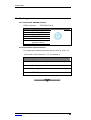
1
PZ 129E User Manual E-651 / E-614 Controller / Amplifier for Bender Actuators Release: 6.0.0 Date: 2004-07-14 This document describes the following Product(s): E-651.1S Piezo Controller/Amplifier for Bender Actuators with SGS, single channel E-651.2S Piezo Controller/ Amplifier for Bender Actuators with SGS, dual channel E-614.2BS Piezo Controller/ Amplifier for Bender Actuators with SGS, OEM version, dual channel © Physik Instrumente (PI) GmbH & Co. KG Auf der Römerstr. 1 ⋅ 76228 Karlsruhe, Germany Tel. +49-721-4846-0 ⋅ Fax: +49-721-4846-299 [email protected] ⋅ www.pi.ws Declaration of Conformity The manufacturer, Physik Instrumente (PI) GmbH & Co. KG Auf der Roemerstrasse 1 76228 Karlsruhe, Germany declares, that the product E-651 / E-614 Controller/amplifier for Bender Actuators complies with these EMC specifications regarding EN-500081-1(3/93), (Generic Standard): EN-55022 (1991), Class B EN-55014 CISPR 22, Class B with these EMC specifications regarding EN-500082-1(3/93), (Generic Standard): IEC 801-2(1991), 4kV contact discharge, 8 kV air discharge IEC 801-3(1994), 3 V/m IEC 801-4(1988), 1 kV line cord, 0.5 kV data lines The product complies with the requirements of the EMC Directive 89/336/EEC and the CE markings have been affixed on the devices. Physik Instrumente (PI) GmbH & Co. KG is the owner of the following company names and trademarks: PICMA® Copyright 1999–2004 by Physik Instrumente (PI) GmbH & Co. KG, Karlsruhe, Germany. The texts, photographs and drawings in this manual enjoy copyright protection. With regard thereto, Physik Instrumente (PI) GmbH & Co. KG reserves all rights. Use of said texts, photographs and drawings is permitted only in parts and only upon citation of the source. First printing 2004-07-14 Document Number PZ 129E, Release 6.0.0 E-614_User_PZ129E600.doc This manual has been provided for information only and product specifications are subject to change without notice. Any change will be reflected in future printings. About this Document Users of this Manual This manual is designed to help the reader to install and operate the E-651 / E-614 Controller/amplifier for Bender Actuators. It assumes that the reader has a fundamental understanding of basic servo systems, as well as motion control concepts and applicable safety procedures. The manual describes the physical specifications and dimensions of the E-651 / E-614 Controller/amplifier for Bender Actuators as well as the hardware installation procedures which are required to put the motion system into operation. Updated releases of this document are available via FTP or email: contact your Physik Instrumente sales engineer or write [email protected] Conventions The notes and symbols used in this manual have the following meanings: WARNING Calls attention to a procedure, practice or condition which, if not correctly performed or adhered to, could result in injury or death. WARNING–HIGH VOLTAGE Indicates the presence of high voltage (> 50 V). Calls attention to a procedure, practice or condition which, if not correctly performed or adhered to, could result in injury or death. ! CAUTION Calls attention to a procedure, practice, or condition which, if not correctly performed or adhered to, could result in damage to equipment. Related Documents E-801 sensor-processing submodules and E-802 servo-control submodules, which are installed on the E-651 / E-614 main board at factory, are described in their own manuals. All documents are available as PDF files via FTP or email: contact your Physik Instrumente sales engineer or write [email protected]: E-801_User_PZ117E E-802UserPZ113E Contents 1 2 Introduction 1.1 Overview .................................................................................... 3 1.2 Safety Precautions ..................................................................... 4 1.3 Model Survey ............................................................................. 6 1.4 Unpacking .................................................................................. 6 1.5 System Requirements................................................................ 7 Starting Operation 2.1 2.2 3 5 6 E-651 Bench-Top Unit................................................................ 9 2.1.1 Element Description.......................................................................................9 2.1.2 Getting Started.............................................................................................11 E-614 OEM PCB ...................................................................... 13 2.2.1 Element Description.....................................................................................14 2.2.2 Getting Started.............................................................................................16 18 3.1 Full Differential-Voltage Control ............................................... 18 3.2 Operating Modes...................................................................... 18 3.2.1 Closed-Loop Operation................................................................................18 3.2.2 Open-Loop Operation ..................................................................................19 On-Board Submodules............................................................. 19 3.3.1 E-801 Submodule for Strain Gauge Sensor Processing..............................19 3.3.2 E-802 Position Servo-Control Submodule ...................................................20 Calibration 21 4.1 Equipment Needed .................................................................. 22 4.2 Zero-Point Adjustment ............................................................. 22 Troubleshooting 24 5.1 Typical Problems...................................................................... 24 5.2 Opening the E-651 Case.......................................................... 25 Technical Data 6.1 www.pi.ws 9 Principles of Operation 3.3 4 3 26 Specifications ........................................................................... 26 E-651 / E-614 PZ 129E Release 6.0.0 Page 1 Contents 6.2 www.pi.ws Pin Assigment .......................................................................... 27 6.2.1 E-651 PZT & SENSOR connector ...............................................................27 6.2.2 E-614 Sensor Input Connectors...................................................................27 E-651 / E-614 PZ 129E Release 6.0.0 Page 2 Introduction 1 Introduction 1.1 Overview E-651 is a bench-top piezo controller, especially designed for low-voltage, multilayer piezo bender actuators such as the P871, which require full differential-voltage control and are equipped with strain gauge sensors. One- and two-channel versions of the E-651 are available. The E-614.2BS OEM board provides the same functionality as the E-651.2S 2-channel controller, but on a printed circuit board. A wide-range power supply is included with the E-651. Fig. 1: E-651-series controller/amplifier (E-651.2S at left, E-651.1S at right) Fig. 2: E-614 OEM controller/amplifier The above devices each comprise a power amplifier, DC sensor excitation and readout circuitry with preamplifier and different filters, together with a proportional-integral (P-I) controller for closed-loop operation. Channels can be operated in either open-loop mode, where the output voltage is controlled by an analog input signal, or closedloop mode, where the displacement (position) of the bender is controlled by the analog input signal. www.pi.ws E-651 / E-614 PZ 129E Release 6.0.0 Page 3 Introduction E-651 / E-614 features at a glance: Controller for Closed-Loop Multilayer "Bimorph" Actuators 1- and 2-Channel Versions Bench-Top and OEM-Board Versions 1.2 Safety Precautions WARNING Failure to heed warnings in this manual can result in bodily injury or material damage. Note that E-651 / E614 Controller/Amplifier do not contain any userserviceable parts. ! CAUTION The E-614.2BS Controller/Amplifier PCB and its submodule boards (E-801, E-802) are ESD-sensitive (electrostatic discharge sensitive) devices. Observe all precautions against static charge buildup before handling these devices. Avoid touching circuit components, pins and PCB traces. Discharge any static charge you may have on your body by briefly touching a conductive, grounded object before you touch any electronic assembly. Pose PCBs only on conductive surfaces, such as ESD-safe transport containers (envelopes, foam). Electronic subassemblies must always be kept and transported/shipped in conductive packaging. Make sure that no conductive particles of any kind (metallic dust or shavings, broken pencil leads, loose screws) contact the device circuitry. WARNING—HIGH VOLTAGE E-651s and E-614s are amplifiers generating high voltages of up to 60 V for driving piezo actuators. The output power may cause serious injuries. www.pi.ws E-651 / E-614 PZ 129E Release 6.0.0 Page 4 Introduction Working with these devices or using piezoelectric products from other manufacturers we strictly advise you to follow the General Accident Prevention Regulations. All work done with and on the devices described here requires adequate knowledge of handling high voltages. ! CAUTION Do not apply any input voltage to the SENSOR MONITOR socket. This could cause damage to the electronics. ! CAUTION Handle bender actuators (ceramic elements!) with care! Do not drop a bender actuator; avoid subjecting it to any kind of mechanical shock. ! CAUTION If you hear or see any resonant behavior, switch off power to the actuator immediately. See the PI catalog or the product documentation for the bender actuators for the unloaded resonant frequency.. ! CAUTION Calibration of the controller is done prior to delivery by the manufacturer. Do not adjust potentiometers unnecessarily. Any calibration procedures are to be carried out by qualified authorized personnel only. www.pi.ws E-651 / E-614 PZ 129E Release 6.0.0 Page 5 Introduction ! CAUTION Do not interchange controller and / or actuators since they are matched and calibrated together. Respect the designation of the actuators to the individual controller channels, which is readily identifiable with the serial numbers of the devices. 1.3 Model Survey The following models are available: Model Description Notes E-651.1S Piezo controller/amplifier for bender actuators with SGS, single channel (for one bender actuator) bench-top unit, see Fig. 1 E-651.2S Piezo controller/amplifier for bender actuators with SGS, dual channel (for up to two bender actuators) bench-top unit, see Fig. 1 E-614.2BS Piezo controller/amplifier for bender actuators with SGS, OEM PCB, dual channel (for up to two bender actuators) PCB for OEM applications, see Fig. 2, functionality corresponds to E-651.2S 1.4 Unpacking ! CAUTION The E-614.2BS Controller/Amplifier PCB and its submodule boards (E-801, E-802) are ESD-sensitive (electrostatic discharge sensitive) devices. Observe all precautions against static charge buildup before handling these devices. Avoid touching circuit components, pins and PCB traces. Discharge any static charge you may have on your body by briefly touching a conductive, grounded www.pi.ws E-651 / E-614 PZ 129E Release 6.0.0 Page 6 Introduction object before you touch any electronic assembly. Pose PCBs only on conductive surfaces, such as ESD-safe transport containers (envelopes, foam). Electronic subassemblies must always be kept and transported/shipped in conductive packaging. Make sure that no conductive particles of any kind (metallic dust or shavings, broken pencil leads, loose screws) contact the device circuitry. Unpack the E-651 / E-614 controller/amplifier with care. Compare the contents against the sales contract and packing slip. The following components should be included with the E-651: E-651 controller/amplifier bench-top device C-890.PS power supply with line cord User Manual for E-651 / E -614 (this document) in printed form The following components should be included with E-614s: E-614 controller/amplifier OEM PCB (with two E801 and two E-802 submodules installed) User Manual for E-651 / E -614 (this document) in printed form Inspect the contents for signs of damage. If parts are missing or you notice damage, such as loose contacts or hairline cracks, please contact PI immediately. Save all packing materials in the event the product need be shipped elsewhere. Contact your PI sales engineer or write [email protected] if you need additional components. 1.5 System Requirements To start working with the E-651 / E- 614 controller/amplifier, you need the following: www.pi.ws Supply voltage in the range of 14 to 16 VDC (C890.PS power supply comes with E-651) E-651 / E-614 PZ 129E Release 6.0.0 Page 7 Introduction www.pi.ws For each channel used, an input control voltage in the range of -5 V to +5 V on a suitable connector (BNC for E-651, Molex for E-614) For each channel used, a multilayer piezo bender actuator with integrated strain gauge sensor (SGS), e.g. P-871, each with suitable connector (7-conductor LEMO for E-651, or Molex for E614) E-651 / E-614 PZ 129E Release 6.0.0 Page 8 Starting Operation 2 Starting Operation Note that upon delivery the system is ready for operation: all of PI's piezo positioning systems are delivered with performance test documents to verify the system performance, and calibration of the controller is done prior to delivery in our lab. Actuators and assigned controller channels are matched and should be kept together as a unit. The serial number of the assigned actuator is marked on the associated controller channel. Normally, you do not need to calibrate the system. Only if the actuator, mechanical setup, cables to the bender actuator are replaced, or if a large change in operating temperature occurs, is recalibration necessary. Should you ever need to make a new full calibration, read section 4 on page 21. 2.1 E-651 Bench-Top Unit 2.1.1 Element Description Fig. 3: E-651 front panel; elements for channel 2 are not present on single-channel models Common elements: ON (Power) LED Power on/off indicator Elements provided once per channel: OFL LED www.pi.ws Lights up if the output voltage is outside the nominal output voltage range of the controller E-651 / E-614 PZ 129E Release 6.0.0 Page 9 Starting Operation ! SERVO ON/OFF Switch for changing between open-loop (off) and closed-loop mode (on) CONTROL IN BNC connector for the analog control signal, -5 V to +5 V CAUTION Do not apply any input voltage to the SENSOR MONITOR socket. This could cause damage to the electronics. SENSOR MONITOR BNC connector for reading out the sensor input signal (0 to 10 V) ZERO This potentiometer shifts the output of the sensor processing circuitry PZT & SENSOR 7-conductor LEMO connector with PZT outputs (constant +60 V and power-amp output 0 to +60 V), as well as sensor excitation (5 V DC) and input signal Fig. 4: E-651 rear panel details www.pi.ws POWER ON/OFF switch 14 to 16V DC INPUT Operating power input, socket for the barrel connector from the C-890.PS power supply (included) E-651 / E-614 PZ 129E Release 6.0.0 Page 10 Starting Operation 2.1.2 Getting Started WARNING—HIGH VOLTAGE E-651s and E-614s are amplifiers generating high voltages of up to 60 V for driving piezo actuators. The output power may cause serious injuries. Working with these devices or using piezoelectric products from other manufacturers we strictly advise you to follow the General Accident Prevention Regulations. All work done with and on the devices described here requires adequate knowledge of handling high voltages. CAUTION Do not apply any input voltage to the SENSOR MONITOR socket. This could cause damage to the electronics. CAUTION Handle bender actuators (ceramic elements!) with care! Do not drop a bender actuator; avoid subjecting it to any kind of mechanical shock. CAUTION If you hear or see any resonant behavior, switch off power to the actuator immediately. See the PI catalog or the product documentation for the bender actuators for the unloaded resonant frequency.. CAUTION Do not interchange controller and/or actuators; they are matched and calibrated together. Respect the www.pi.ws E-651 / E-614 PZ 129E Release 6.0.0 Page 11 ! ! ! ! Starting Operation assignment of the actuators to the individual controller channels, as indicated by the serial numbers on the labels affixed to the devices. Carry out the following steps to put the motion system into operation: 1. Connect the actuators to the proper controller channel(s) using the PZT & SENSOR socket(s). Handle the actuators with care and avoid any kind of mechanical shock. 2. Optionally: If you want to read out the sensor signal for a channel, connect a voltmeter (not included) to the appropriate SENSOR MONITOR socket. 3. With the POWER switch on the rear panel set to OFF, connect the controller to the C-890.PS power supply (included) using the 14 to 16 VDC INPUT socket, and connect the power supply to the line power (100–240 VAC, 50/60 Hz). 4. Select the operating mode for each channel using the corresponding SERVO ON/OFF switch on the controller. If SERVO is ON (closed-loop mode), the control input voltage is used as the target position value for the servo-control circuit, and determines the position of the bender. If SERVO is OFF (openloop mode), the output voltage for the bender actuator is in direct linear relation to the control input voltage. 5. Connect a control-input voltage source (-5 V to +5 V DC) to the CONTROL INPUT socket for each controller channel. 6. Power up the E-651 controller using the POWER switch on the rear panel. The POWER LED on the front panel lights up. 7. Deflect the actuator(s): apply a control input voltage in the range from -5 V to +5 V to the channel(s). You can monitor the actuator deflection with the SENSOR MONITOR signal (see step 2; 0 V to 10 V), even when the system is in open-loop mode. If the output voltage corresponding to the control www.pi.ws E-651 / E-614 PZ 129E Release 6.0.0 Page 12 Starting Operation input signal is outside the output voltage range (0 to 60 V), the OFL (overflow) LED for the channel lights and remains on as long as the overflow condition persists. 2.2 E-614 OEM PCB ! CAUTION The E-614.2BS Controller/Amplifier PCB and its submodule boards (E-801, E-802) are ESD-sensitive (electrostatic discharge sensitive) devices. Observe all precautions against static charge buildup before handling these devices. Avoid touching circuit components, pins and PCB traces. Discharge any static charge you may have on your body by briefly touching a conductive, grounded object before you touch any electronic assembly. Pose PCBs only on conductive surfaces, such as ESD-safe transport containers (envelopes, foam). Electronic subassemblies must always be kept and transported/shipped in conductive packaging. Make sure that no conductive particles of any kind (metallic dust or shavings, broken pencil leads, loose screws) contact the device circuitry. www.pi.ws E-651 / E-614 PZ 129E Release 6.0.0 Page 13 Starting Operation 2.2.1 Element Description connection for power-on LED, pin 1 = cathode Fig. 5. Connections overview www.pi.ws E-651 / E-614 PZ 129E Release 6.0.0 actuator exitation, ch 1 & ch2 (+62 V and changeable output voltage ) Control input, ch 2 & 1 Overflow LED, ch 1 Sensor input, ch 1 Offset pot, ch 1 Sensor input, ch 2 Overflow LED, ch 2 Offset pot, ch 2 Mating connectors with color-coded, open-end conductors are provided. See Fig. 6 and p. 15 for pinouts. supply voltage -15 V GND +15 V Page 14 Starting Operation EC/VC switch: EC enables servo-control (closed –loop mode). ECsetting is superseded, if SW2 and SW3 are set to U (open-loop)! SW2: U–G switch, U to bypass E-802 servocontrol submodule for channel 2 completely (open-loop "amplifier-only" operation); G to enable SW3: U–G switch, U to bypass E-802 servocontrol submodule for channel 1 completely (open-loop "amplifier-only" operation); G to enable X7: Short to activate offset pot for channel 2 (connected to X16) X10: Short to activate offset pot for channel 1 (connected to X18) MON-DMS1, MONDMS2: Strain gauge sensor monitor test point R-132: Zero potentiometer for channel 1 R-133: Zero potentiometer for channel 2 X13: Supply, pin 1 +14 to +16 V, pin 2 GND X14: connection for offboard power-on LED H2: Overflow LED for channel 1 H3: Overflow LED for channel 2 For more pinouts see p. 27 Component layout on E801 and E-802 submodules depends on submodule model installed. See submodule User Manuals for details. Fig. 6. Component and connection locations in detail; important adjustment and test elements circled www.pi.ws E-651 / E-614 PZ 129E Release 6.0.0 Page 15 Starting Operation 2.2.2 Getting Started WARNING—HIGH VOLTAGE E-651s and E-614s are amplifiers generating high voltages of up to 60 V for driving piezo actuators. The output power may cause serious injuries. Working with these devices or using piezoelectric products from other manufacturers we strictly advise you to follow the General Accident Prevention Regulations. All work done with and on the devices described here requires adequate knowledge of handling high voltages. ! CAUTION ! CAUTION ! CAUTION Handle bender actuators (ceramic elements!) with care! Do not drop a bender actuator; avoid subjecting it to any kind of mechanical shock. If you hear or see any resonant behavior, switch off power to the actuator immediately. See the PI catalog or the product documentation for the bender actuators for the unloaded resonant frequency. Do not interchange controller and / or actuators since they are matched and calibrated together. Respect the designation of the actuators to the individual controller channels, which is readily identifiable with the serial numbers of the devices. Carry out the following steps to put the motion system into operation (for component location and pinouts see Fig. 6): www.pi.ws E-651 / E-614 PZ 129E Release 6.0.0 Page 16 Starting Operation 1. Connect the piezo actuators to the controller board using the X21 socket. Handle the actuators with care and avoid any kind of mechanical shock. 2. Optionally: If you want to use the sensor signal for a channel, connect your electronics to the corresponding MON-DMS test point (Fig. 6). 3. Select the operating mode (open-loop or closed loop) for each channel using the SW2 and SW3 switches and the EC/VC switch. For details see p. 18. 4. Connect the control-input voltages (-5 V to +5 V DC) for the controller channels to the X20 socket. 5. Connect the supply power (14 to 16 VDC) to the X15 supply power connector. If you have connected an (optional) POWER LED to the X14 socket, it will light up. 6. Deflect the actuator(s): apply a control input voltage in the range from -5 V to +5 V to the channel(s). You can monitor the actuator deflection with the SENSOR MONITOR signal (see step 2; 0 V to 10 V), even when the system is operated in open-loop mode. If the output voltage corresponding to the control input signal is outside the output voltage range (0 to 60 V), the OFL (overflow) LED for the channel lights and remains on as long as the overflow condition persists. www.pi.ws E-651 / E-614 PZ 129E Release 6.0.0 Page 17 Principles of Operation 3 Principles of Operation 3.1 Full Differential-Voltage Control E-651/E-614 controller/amplifiers are specially designed to operate PICMA™ multilayer bender actuators from PI (see PI catalog). These actuators require full differential-voltage control with constant voltages of 0 V and +60 V and a variable voltage from 0 V to +60 V (see Fig. 7). Note that a control input voltage of 0 V corresponds to a PZT variable output of about +30 V, which puts the actuator in the middle position (i.e. deflection ≈ 0 µm). Fig. 7. PICMA™ multilayer bender actuator with full differential-voltage control, Pin assignment: 1 -0 V [or GND] 2 -0 V to +60 V 3 +60 V 3.2 Operating Modes E-651 / E-614 controller/amplifiers can be operated in closedloop or open-loop mode. The position signal is available in either operating mode in the form of a sensor monitor signal from 0 to 10 V. Note that +5 V corresponds to mid-position of the actuator. 3.2.1 Closed-Loop Operation In closed-loop mode, it is the deflection (position) of the bender that is controlled by the control input signal, which is processed by the E-802 servo-control submodule (see section 3.3.2). An E-651 channel is in closed-loop mode if the corresponding SERVO switch on the front panel is set to ON. www.pi.ws E-651 / E-614 PZ 129E Release 6.0.0 Page 18 Principles of Operation An E-614 channel operates in closed-loop mode, if EC/VC switch is set to EC and Switch SW3 (channel 1) and SW2 (channel 2) are set to G (if one of these switches is set to U, the corresponding channel is in open-loop mode, even if the EC/VC switch is set to EC) For component location see Fig. 6 on p. 15. 3.2.2 Open-Loop Operation In open-loop mode the variable output voltage for the actuator is controlled by the control input signal (this output voltage for the bender actuator is in direct linear relation to the control input voltage). An E-651 channel is in open-loop mode, if the corresponding SERVO switch on the front panel is set to OFF. An E-614 channel is in open-loop mode, if EC/VC switch is set to VC (both channels) or Switch SW3 (channel 1) or SW2 (channel 2) is set to U For component location see Fig. 6 on p. 15. 3.3 On-Board Submodules Each E-651 / E-614 channel is equipped with submodules for sensor processing (E-801) and servo-control (E-802). If you ever have to remove and replace any of the submodules, be sure to preserve the orientation of the component sides as shown in Fig. 6 on p. 15. 3.3.1 E-801 Submodule for Strain Gauge Sensor Processing This submodule is used for excitation and evaluation of one strain gauge sensor (SGS). It is designed as a plug-in submodule to be used on different PCBs. The submodule supplies the strain gauge with a DC voltage and generates a signal proportional to the expansion changes of the strain gauge. Located on the submodule is a sensor gain adjustment and settings for a low-pass filter. www.pi.ws E-651 / E-614 PZ 129E Release 6.0.0 Page 19 Principles of Operation See the SGS portions of the E-801 User Manual for details. 3.3.2 E-802 Position Servo-Control Submodule The E-802 submodule produces an analog control signal for the power amplifier driving the actuator. Slew rate limitation, notch filter and servo-control loop are all implemented on the E-802. The servo-loop logic compares the control voltage input (target) and the sensor signal (current position) to generate the amplifier control signal using an analog proportional-integral (PI) algorithm. For calibration procedures, see Section 4 and the E-802 ServoControl Submodule User Manual. www.pi.ws E-651 / E-614 PZ 129E Release 6.0.0 Page 20 Calibration 4 Calibration Note that upon delivery the system is ready for operation: all of PI's positioning systems with a piezo actuator are delivered with performance test documents to verify the system performance, and calibration of the controller is done prior to delivery in our lab. Actuators and assigned controller channels are matched and should be kept together as a unit. The serial number of the actuator assigned to each channel is marked on the individual controller. Normally there is no need for you to recalibrate the system. Only exchanging the actuator, the mechanical setup, replacing the cables on the actuator or making a large change in the operating temperature, may make recalibration necessary. The only procedure which is necessary from time to time is the zero-point adjustment (see below). All other calibration procedures—static gain adjustment1 and dynamic calibration2— require special equipment and should only be done by qualified personnel and are required only in special circumstances. See the user manuals for the sensor processing and servo-control submodules (E-801 and E-802) for details regarding those procedures. WARNING—HIGH VOLTAGE E-651s and E-614s are amplifiers generating high voltages of up to 60 V for driving piezo actuators. The output power may cause serious injuries. Working with these devices or using piezoelectric products from other manufacturers we strictly advise you to follow the General Accident Prevention Regulations. All work done with and on the devices described here requires adequate knowledge of handling high voltages. 1 The objective of static gain adjustment is to ensure that the actuator expands to its nominal expansion in "positive" direction when a control signal input of +5 V is applied (with DC-offset disabled). 2 Dynamic calibration optimizes step response and suppresses resonance, overshoot, and oscillation. www.pi.ws E-651 / E-614 PZ 129E Release 6.0.0 Page 21 Calibration ! CAUTION The E-651 and E-614 controller/amplifier PCBs and their submodule boards (E-801, E-802) are ESDsensitive (electrostatic discharge sensitive) devices. Observe all precautions against static charge buildup before handling these devices. Avoid touching circuit components, pins and PCB traces. Discharge any static charge you may have on your body by briefly touching a conductive, grounded object before you touch any electronic assembly. Pose PCBs only on conductive surfaces, such as ESD-safe transport containers (envelopes, foam). Electronic subassemblies must always be kept and transported/shipped in conductive packaging. Make sure that no conductive particles of any kind (metallic dust or shavings, broken pencil leads, loose screws) get on the card. ! CAUTION Calibration of the controller is done prior to delivery by the manufacturer. Do not adjust potentiometers unnecessarily. Any calibration procedures are to be carried out by qualified authorized personnel only. 4.1 Equipment Needed Zero-point adjustment requires a voltmeter and a small straightbladed screw driver. 4.2 Zero-Point Adjustment Proper zero-point adjustment ensures that the full output voltage swing of the amplifier can be used without reaching the output voltage limits of the amplifier and causing overflow conditions, both in open-loop and closed-loop operation. If an overflow condition occurs (OFL LED lights up for the channel), it can often be prevented by re-adjusting the ZERO point. The zero-point of each channel is adjusted with the appropriate ZERO potentiometer (E-651: ZERO potentiometer for each accessible through the front panel; E-614: R132 for channel 1, www.pi.ws E-651 / E-614 PZ 129E Release 6.0.0 Page 22 Calibration R133 for channel 2; see p. 15 for component locations). This potentiometer shifts the output of the sensor processing circuitry and hence the values on the sensor monitor output (E651: front panel; E-614: MON-DMS1 and MON-DMS2 test points) and sensor-input lines of the servo-loop submodule. To adjust the zero-point for a channel proceed as follows: 1. Before powering up the system, make sure the actuator is mounted in the same way and with the same load as during normal operations in the application. In multi-axis systems, make sure the actuators are always connected to the same controller channels. 2. Make sure the analog control input (E-651: front panel; E-614: connector X20) is at 0 V. 3. Set the channel to open-loop mode (E-651: SERVO OFF; E-614: EC/VC switch (p. 15) to VC) 4. E-614 only: close jumper X7 (channel 2) and X10 (channel 1) to disable any DC offset potentiometer. 5. Power up the system. 6. Deflect the actuator over its full range by sweeping the control input signal over the range of -5 V to +5 V. 7. Hold the control input signal at -5 V. 8. Adjust the ZERO potentiometer so that the sensor- monitor signal is 0 V. Normally the zero-point adjustment can be finished at this point. Now you can switch the channel to closed-loop mode and deflect the actuator over the full range by applying a control input voltage of -5 to +5 V. The overflow LED should not light up. If the overflow LED does light, repeat steps 2 to 8. Failure of the zero-point re-adjustment (i.e. overflow LED still lights up) could indicate a serious problem. See "Troubleshooting" section for information on how to proceed. www.pi.ws E-651 / E-614 PZ 129E Release 6.0.0 Page 23 Troubleshooting 5 Troubleshooting 5.1 Typical Problems Problem Possible Causes Solutions Actuator does not move Cables not connected or connected to wrong socket Check the connecting cables Cable is defective Contact your PI sales engineer or write [email protected]. Bender actuator defective Replace actuator with a working one, to test a new combination of actuator and controller (note that if you want to use the new actuator in regular operation a fully recalibration of the system is required) and contact your PI sales engineer or write [email protected]. Control input voltage source defective Repair or replace voltage source Controller will not power up Check POWER LED (with E-614 not included), power supply and line voltage connection Commanded output voltage outside the allowed range (0 to +60 V) Re-adjust the zero-point (see p. 22). If this is not successful, contact your PI sales engineer or write [email protected]. Control input signal outside the allowed range (-5 V to +5 V) Use a suitable control input signal Overflow LED lights up www.pi.ws E-651 / E-614 PZ 129E Release 6.0.0 Page 24 Troubleshooting 5.2 Opening the E-651 Case ! CAUTION Note that E-651 / E-614 controller/amplifier do not contain any user-serviceable parts. Some adjustment elements on the main board and on the E-801 and E-802 submodules are covered with sealing lacquer. Damage to the seal will void the warranty except in consultation with PI. Should it ever be necessary to open the E-651 case, e.g. for a static gain adjustment procedure, proceed as follows: 1. Switch off the controller and disconnect the power supply. 2. Use a Torx 8 driver to unscrew the 2 screws in the blue frame on the rear panel and carefully remove the rear panel. 3. Use the Torx 8 driver to unscrew the 2 screws in the blue frame on the front panel. Carefully remove the front panel, which also pulls the PCB out of the case (the rear panel must be turned and pulled carefully through the case too). 4. Reconnect the power supply to the socket on the rear panel. Keep the system powered down. www.pi.ws E-651 / E-614 PZ 129E Release 6.0.0 Page 25 Technical Data 6 Technical Data 6.1 Specifications Model Function E-651.1S Power amplifier & sensor/position servocontroller for multilayer bender actuators, bench-top controller 1 E-651.2S Power amplifier & sensor/position servocontroller for multilayer bender actuators, bench-top controller 2 E-614.2BS Power amplifier & sensor/position servo-controller for multilayer bender actuators, OEM board 2 1W 1 W / channel 1 W / channel 0.5 W 0.5 W / channel 0.5 W / channel 36 mA 36 mA 36 mA 18 mA 18 mA 18 mA 6 Positive -5 V to +5 V 6 Positive -5 V to +5 V 6 Positive -5 V to +5 V 0 V to +60 V - 0 V to +60 V - Input Impedance Control input socket PZT (bender actuator) voltage and sensor input socket POSITION SERVOCONTROL Sensor Type Sensor excitation Low-pass cut-off frequency Monitor output 100 kΩ BNC 100 kΩ BNC 0 V to +60 V 0 to +60 V with ext. potentiometer (not included) 100 kΩ On-board connector LEMO EPG.0B.307.HLN, sensor and PZT lines in one connector LEMO EPG.0B.307.HLN, sensor and PZT lines in one connector Separate on-board connectors for PZT output voltages and senor input SGS 5 V DC, adjustable SGS 5 V DC, adjustable SGS 5 V DC, adjustable 100 Hz / 5 kHz selectable 0 V to +10 V for nominal displacement 100 Hz / 5 kHz selectable 0 V to +10 V for nominal displacement Sensor monitor output socket Dimensions BNC BNC 100 Hz / 5 kHz selectable 0 V to +10 V for nominal displacement On-board connector 125 x 90 x 265 mm 125 x 90 x 265 mm Weight Operating voltage 1.36 kg 14 to 16 V DC (power supply C-890.PS included) 1.45 kg 14 to 16 V DC (power supply C-890.PS included) Channels AMPLIFIER: Maximum output power Average output power Peak output current 5 ms Average output current Voltage gain Polarity Control input voltage Output voltage DC offset setting www.pi.ws Open frame board, 100 x 40 x 200 mm 0.30 kg 14 to 16 V DC E-651 / E-614 PZ 129E Release 6.0.0 Page 26 Technical Data 6.2 Pin Assigment 6.2.1 E-651 PZT & SENSOR connector LEMO connector Pin 1 2 3 4 5 6 EPG.0B.307.HLN Function GND (actuator) Sensor input (-) Sensor input (+) GND (SGS) + 60 V Variable output voltage (actuator control) SGS reference voltage 7 6.2.2 E-614 Sensor Input Connectors For component locations and more pinouts see Fig. 6 on p. 15. (Connector X19 for channel 1, X17 for channel 2) Pin www.pi.ws Function 1 SGS reference voltage 2 Sensor input (+) 3 Sensor input (-) 4 SGS GND E-651 / E-614 PZ 129E Release 6.0.0 Page 27