Download Catalog VPInstruments (Global version)
Transcript
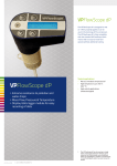
Energy Management solutions for compressed air and industrial gases vp i n s t r um e n t s. com ‘ Vision is a really powerful tool to keep our compressed air consumption at the lowest possible level. It helps us to prevent leakage and to optimize our compressed air supply.’ - Kikkoman Europe CAT-VP-UK-1501 © 2015 VPINSTRUMENTS Introduction | VPINSTRUMENTS 3 Our mission VPInstruments develops, produces and supplies energy management solutions for compressed air and industrial gases. We show you where, when and how much you can save. Our solutions cover both supply side and demand side. We offer a unique product range consisting of: > > > Insertion and in-line flow meters and other sensors for compressed air and technical gases Energy Management Software for compressed air and all other utilities Easy to use tools for installation VPInstruments is one of the most innovative companies in its industry. Our products and solutions are often unique in the market, easy to use, sustainably produced, and designed with two eyes for detail, which is reflected in our logo. Our products are sold through skilled distributors worldwide. Thanks to their skills and expertise, they help you to get the most out of our products. We take quality and traceability very seriously. Our calibration systems are traceable to the National Standards at NMi (Dutch Institute of Standards and Metrology). Our quality management system is certified to ISO 9001:2008. Proudly serving leading companies worldwide Through our distributors and dealers, we serve clients worldwide to save on compressed air energy costs. A small selection of end users: Astrum UK (Steel castings), Bolletje (Food), GSK (Medicines), Kikkoman Foods, Libbey (Glass), Mars (Food), Nedstaal (Steel production), Nestlé (Food), O&I (Glass), Philips (Consumer goods), Rexam (Glass), Toyota (Automotive). Histor y Since 1974, the founders of VPInstruments have invested over 40 years in research In 1999, VPInstruments is founded by Pascal van Putten, and wins the McKinsey New Venture ’98 competition 15 In 2007, The VPFlowScope product line is launched For the first time, mass flow, pressure and temperature can be measured with a single probe YEARS In 2009, VPVision is introduced. The complete solution for compressed air energy management In 2011, The VPFlowScope Differential Pressure flow meter is introduced. Now you can perform air audits in wet, condensing air conditions In 2013, VPInstruments again sets the standard with a three in one in-line flow sensor 04-11-14 VPIN1412 CAT-VP-UK-1501 Boekje 15 1 druk.indd jaar gewher © 2015 VPINSTRUMENTS 09:04 In 2014: VPInstruments celebrates their 15 year anniversary 4 Introduction | VPINSTRUMENTS Technology Thermabridge- leading sensor technology since 1974 Our co-founder Anton Van Putten invented the world’s first solid state thermal mass flow sensor back in 1974. We are proud to continue the heritage of making cutting edge products based upon this unique and patented sensor technology. Working principle The unique Thermabridge™ sensors are integrated circuits, just like computer chips. They combine a heater with a Wheatstone bridge. The heater keeps the sensor on a constant temperature. The Wheatstone bridge is used for temperature control and direction measurement. Direction sensitivity. Invented by VPInstruments The VPFlowScope combines an extremely large measurement range with integrated direction sensitivity. This patented feature enables you to measure in loop networks, and in systems with air receivers. These situations used to be very difficult to assess. With the VPFlowScope, flow direction is no longer a mystery. Modbus - the industry standard The VPFlowScope provides a Modbus-RTU interface, which opens the door to many energy management software packages and building management systems. No secret protocols or expensive configuration tools needed. Sensing the future Since 1974, the founders of VPInstruments have invested over 40 years in research and development. We will continue to do so, to enhance our products and our technology, in our effort to provide the best possible solutions for mass flow measurement of compressed air and technical gases. The unique Thermabridge™ sensors combine a heating element with a Wheatstone bridge. Flow CAT-VP-UK-1501 Flow Flow from left No flow Flow from right The left part is cooled down, the right part of the bridge is heated up. Everything in balance. Vice versa! Now the left part is heated up, and the right part is cooled down. © 2015 VPINSTRUMENTS Introduction | VPINSTRUMENTS If you can measure it, you can improve it Measurep11 Use mass flow meters for: >Supply side air: pre-treated wet oily dirty air >Demand side air: clean dry air >Piping systems from 0.5" up to 20": measuring and recording mass flow, temperature and pressure in a single measuring instrument >Air audits, system checks Monitorp27 Leave measuring equipment in place to: >Continually know what is happening in your system >Proactively control leaks >Plan your maintenance based on real-time actions >Monitor dew point, power consumption and pressure loss to prevent downtime Managep31 With VPVision you can: >Track and manage your leakage >Allocate compressed air costs to individual departments >Deliver cost evaluation and savings reports >Benchmark different plants around the world on efficiency and costs >Produce necessary documentation for utility incentives Installp35 We offer a line of tools and accessories for: >Hot tapping: Installation of flow meters under pressurized conditions >Leak detection >Measuring pipe wall thickness CAT-VP-UK-1501 © 2015 VPINSTRUMENTS 5 6 Introduction | VPINSTRUMENTS 50 30% Measure, Discover and Save! Compressed air is a very expensive energy source. In fact, it is nearly 10 times more expensive than electricity. Compressed air consumption Production Leaks Artificial demand Inappropriate use Studies show that up to 50% of generated compressed air is still lost due to leakage, incompetent use and overdue maintenance. Our products enable you to chart these losses easily. In many cases, compressed air demand can be reduced by optimizing the compressed air system with proper air management, pressure control, piping configurations and air leak control. Fact: Only 50% of the generated compressed air is used usefully. The other 50% is being spilled. A management system will help you to reduce this waste of energy and money, and helps you to maintain your consumption as low as possible. Maximize your ROI Your return on investment can be a matter of months. Take a look at customer savings success stories on our website, and read how our products have helped companies save energy year after year. An n u a l e l e c tri c i ty b i ll kW 25 kW/Year 109,500 Euro USD Euro/Year USD/Year ROI (days) €16,425 $19,710 €4,928 $5,913 365 37 162,060 €24,309 $29,171 €7,293 $8,751 247 55 240,900 €36,135 $43,362 €10,841 $13,009 166 125 547,500 €82,125 $98,550 €24,638 $29,565 73 250 1,095,000 €164,250 $197,100 €49,275 $59,130 37 Equipment investment Leakage/savings potential Production hours per day kW price CAT-VP-UK-1501 S avi n g s p o t e n t ia l © 2015 VPINSTRUMENTS €5,000 30% 12 €0.15 Did you know that a 2 inch in-line meter guards a cash flow of more than 10,000 Euro per year? The ROI is in general a matter of months! See our website for more savings examples and calculators. Introduction | VPINSTRUMENTS 7 Compressed air applications Virtually any production plant utilizes compressed air. Applications are packaging machines, offset presses, transport of granulate and food ingredients, cooling of products, and tank aeration. > Ceramic factories > Glass production > Cement and construction products >Paper >Food production, beverage and breweries > Life sciences >Automotive > Steel production Other markets and applications Our products are used successfully in various industrial applications, for example: > Aeration monitoring in water treatment plants > Airflow monitoring in large ducts > General test and measurement applications (such as universities) > OEM applications > Combustion air mixing > Technical gas mixing > Welding gas, packaging gas > C02 consumption metering > C02 exhaust metering CAT-VP-UK-1501 © 2015 VPINSTRUMENTS 8 Introduction | VPINSTRUMENTS Application examples and start kits We offer start kits, which can be directly applied to your application. Each start kit contains all the items you need for the job. Portable audit tools The VPFlowScope® measures mass flow, pressure, and temperature and features a built-in two million point data logger. The device has a built-in display with keypad for configuration: no need to bring a computer on-site! The start kit is delivered in a heavy duty weather proof transport case. Complete with a portable power supply adapter, cables and VPStudio™ software. Or der codes VPFlowScope® VPS.R150.P400.KIT VPS.R200.P4DP.KIT VPFlowScope start kit for dry air VPFlowScope start kit for wet air, high temperature Demand side measurement For small compressors, demand side and point of use measurement, we offer the VPFlowScope in-line three in one mass flow meter with built-in two million point data logger and USB interface. We offer three models that fit virtually all demand side applications. Pip e siz e s 1 2 DN Thread1 Models Capa c i t y Qmin (m3n/hr) Qmax (m3n/hr) Qmin (scfm)2 Qmax (scfm)2 15 1/2 ‘’ VPS.R080.M050 0.32 60 0.2 35 25 1 ‘’ VPS.R250.M100 0.88 200 0.52 120 50 2 ‘’ VPS.R01K.M200 3.53 1000 2.08 590 All models supplied with BSP thread (straight). For US NPT, an adapter is available SCFM values are rounded off Power supply and interface options All power supplies are rated for 90 to 230 V input with 12 to 24 V output and supplied with correct plug for the country of destination. CAT-VP-UK-1501 Or der cod e sDe s c rip ti on A ppli c a t i o n VPA.0000.200 VPA.5000.005 Light industrial, portable use Fixed installations, control panels © 2015 VPINSTRUMENTS Power supply with M12 connector M12 cable, 5 meter Introduction | VPINSTRUMENTS 9 Compressed air supply monitoring For overall efficiency and cost monitoring we provide a complete solution. It consists of the VPFlowTerminal wall mount display, the VPFlowScope and an AC current sensor. With an optional dew point sensor, you can also monitor the dew point to make sure it is within the specified range. Or der codes VPT.5110.000 VPFlowTerminal for VPFlowScope. Including display with built-in data logger. Pre-mounted connector for VPFlowScope. Built-in power supply. Includes black connector cap with cable 10m/32.9ft, 4 Analogue inputs for VPFlowTerminal. Data will be logged simultaneously. Configuration and read out with VPStudio. Flow meters VPS.R200.P4DP VPS.R150.P400 Flow, pressure, temperature measurement, for wet air Flow, pressure, temperature measurement, for dry air Current sensors VPA.8000.2100 VPA.8000.2200 VPA.8000.2400 VPA.8000.2800 VPA.8000.21K5 VPLog-i AC current sensor 100A-rms VPLog-i AC current sensor 200A-rms VPLog-i AC current sensor 400A-rms VPLog-i AC current sensor 800A-rms VPLog-i AC current sensor 1500A-rms Dew point sensors App lication DEW PO INT Connection ORDER CODEs Adsorption dryer Refrigerant dryer -100 ... +20°C | -148 ... 68°F -40 ... +60°C | -40 ...140 °F 4 ... 20 mA 2 wire 4 ... 20 mA 3 wire VPA.8000.1003 VPA.8000.1013 Example: VPFlowTerminal for local data logging > 1 VPFlowScope > 3 parameters on local display > Up to 8 parameters to be logged > Example: 4 analog inputs (4 ... 20 mA) > 2 Current clamps (Amps) > 1 Pressure sensor (Air treatment DP) > 1 dew point meter (Air treatment Quality) >VPFlowScope and all 4 ... 20 mA signals can be patched to DCS CAT-VP-UK-1501 © 2015 VPINSTRUMENTS 10 Introduction | VPINSTRUMENTS Service programs Our service programs provide you with a time- and money saving solution for your VPFlowScope in-line flow meters and insertion probes. With the VPInstruments service programs your equipment will retain their high quality standard and the accuracy you need for your process. Our pressurized calibration systems are state of the art, strictly maintained under the ISO 9001 certified Quality Management System. VPInstruments understand the importance of continuity in your production processes and production data. We use the latest lean process improvement techniques to speed up our service processes. Our fully automated calibration process and our 99.97% first pass parts order fill rate are constantly helping to minimize your service order turnaround time. Our unique back-up and restore offering keeps your settings secure and reduces your set-up time after the service to zero. Or der codes VPA.0001.920 Standard service subscription. A three or five year contract that includes Parts replacement, Repair, Preventive maintenance. Hardware- and software upgrades. For one fixed price. VPA.0001.940 CAT-VP-UK-1501 © 2015 VPINSTRUMENTS Exchange service subscription. A three or five year contract. Receive annually a calibrated instrument and exchange it for the instrument in your prossession. Lifetime warranty extension. No service waiting time. Measure ‘If you can measure it, you can improve it’ - Lord Kelvin CAT-VP-UK-1501 © 2015 VPINSTRUMENTS VPFlowScope The VPFlowScope measures mass flow, temperature and pressure simultaneously. It’s the ultimate compressed air audit tool, used by leading auditors worldwide. The bright blue display provides real-time information, and with the built-in data logger, recording is as easy as taking a picture. VPStudio software can be used for real-time measurements on your PC, to process data and to print reports. The VPFlowScope product family consists of a wet and a dry air flow meter, which are fully interchangeable and compatible with the VPFlowScope display modules. Applications FlowScope > Mass Flow, Pressure & Temperature > Display/data logger module for easy recording of data > Bi-directional measurements (optional) CAT-VP-UK-1501 © 2015 VPINSTRUMENTS >Air audits >Demand side monitoring, sub metering of compressed air >Ring networks (bi-directional) >Air, Nitrogen, Carbon Dioxide, Argon, and any other dry and non-corrosive gases We offer the VPFlowScope for both wet and dry compressed air. You can combine either sensor module with the same display module. That’s why the VPFlowscope is such an exceptional instrument for air auditors. With the VPFlowScope you can measure virtually any compressed air system using a single instrument. FLOWSCOPE | VPINSTRUMENTS 13 Specifications VPFlow Scope Flow sensor Measuring principle Flow range Accuracy Reference conditions Gases Gas temperature range Thermabridge™ Thermal Mass Flow sensor 0 (0.5) ... 150 mn/sec | 0 ... 500 sfps Bi-directional option (calibrated in positive direction only). 2% of reading under calibration conditions; Please refer to the user manual for details. Recommended pipe diameter: 25 mm (1 inch) and up. 0 °C, 1013.25 mbar | 32 °F, 14.65 psi Compressed air, Nitrogen and inert, non condensing gases 0 ... +60 °C | 0 ... +140 °F Pressure sensor Pressure sensor range PN16 Accuracy Pressure sensor range PN35 (optional) 0 ... 16 bar | 0 ... 250 psi gauge +/- 1.5% FSS Temperature compensated 0 ... 35 bar | 0 ... 500 psi gauge Temperature sensor Temperature sensor range Accuracy 0 ... +60 °C | 0 ... +140 °F > 10 m/sec: +/- 1 °C | 1.8 °F < 10 m/sec: + 5 °C | 1.8 °F Data outputs Digital Analog RS485, MODBUS RTU protocol 4 ... 20 mA output, selectable via software to indicate flow, pressure or temperature Display/data logger Technology Back light Data logger Liquid Crystal (LCD) Blue, with auto power save 2 million points Mechanical & environmental Probe lengths Process connection Pressure rating Protection grade Ambient temperature range Wetted materials Corrosion resistance 400 mm | 15 inch (other lengths on request) Compression fitting, 0,5 inch PN16 | PN35 IP52 | NEMA 12 when mated to display module, avoid upside down installation IP63 | NEMA 4 when mated to connector cap, avoid upside down installation -10 ... +50 °C | 14 ... 122 °F. Avoid direct sunlight or radiant heat Higher ambient temperatures: consult factory Anodized Aluminum, Stainless steel 316, Glass, Epoxy Highly corrosive or acid environments should be avoided Electrical Connection type Power supply Power consumption UL/ CUL CE CAT-VP-UK-1501 © 2015 VPINSTRUMENTS M12, 5 pin connector, female 12 ... 24 VDC +/- 10 % Class 2 (UL) 2,4 Watt (no flow) 4,8 Watt (full flow) +/- 10% 100 mA (no flow). 200 mA (full flow) +/- 10% @24VDC 14 AZ, Industrial Control Equipment EN 61326-1, EN 50082-1 14 FLOWSCOPE | VPINSTRUMENTS 3 4 5 6 Technical drawings 45 1.8 12.70 0.5 A P300: 290 mm [11.5] P400: 390 mm [15.4] P600: 590 mm [23.3] 120 4.7 B Or der codes Flow meters VPS.R150.P400.KIT VPFlowScope start kit, for air audits, complete with software VPS.R150.P400.D11VPFlowScope with 2 million point data logger display module, for auditors and permanent installation (stand alone) VPS.R150.P400.D10 VPFlowScope with three row display VPS.R150.P400.D2 VPFlowScope with connector cap. For modbus networks C Other probe lengths The standard P400 probe is acceptable for most air audits and installations. We offer P300 and P600 probes on request. Material : Drawing nr. : Debur and break sharp edges FinishCable, : VPA.5000.005 Unless otherwise specified M12, 5 pole, for permanent connection dimensions are in VPA.5001.105 millimeters Interface box JB5 with 5m/ 16.4 ft cable + 12 VDC power supply Name : Tolerances : Approvals VPA.5001.900 Linear : NEN-ISO 2768-1-m Connector cap with M12 socket for VPFlowScope sensor module ENG QA PROD Other :NEN-ISO 2768-2-K Further info acc. to : Scale : 1:5 Drawn: "Toleranties VPInstruments NEN ISO 2768" Date : SHEET 1 OF 1 VPS.R150.P400 flow range table Accessories VPSR150.P400 A4 All rights are reserved. Reproduction in whole or in part is prohibited without the written consent of the copyright owner. S chedu le 4 0 Stand a rd S e aml e ss Carb on S te e l P ip e Size (inch) DN ID (inch) ID (mm) Min flow (scfm) Max flow (scfm) (m3n/hr) Min flow Schedule 10 Standard Seamless Carbon Steel Pipe Max flow (m3n/hr) ID (inch) ID (mm) Min flow (scfm) Max flow (scfm) Min flow (m3n/hr) Max flow (m3n/hr) 2 50 2.1 52.5 2 688 4 1,169 2.2 54.8 2 749 4 1,273 3 80 3.1 77.9 5 1,516 9 2,576 3.3 82.8 6 1,712 10 2,908 4 100 4.0 102.3 9 2,610 15 4,435 4.3 108.2 10 2,923 17 4,966 6 150 6.1 154.1 20 5,924 34 10,065 6.4 161.5 22 6,508 37 11,057 8 200 8.0 202.7 34 10,259 58 17,429 8.3 211.6 37 11,173 63 18,982 10 250 10.2 259.1 56 16,756 95 28,468 10.4 264.7 58 17,487 99 29,709 12 300 11.9 303.2 77 22,953 130 38,995 12.4 314.7 82 24,724 140 42,004 16 400 15.0 381.0 121 36,237 205 61,565 15.6 396.8 131 39,315 223 66,794 20 500 18.8 477.8 190 56,996 323 96,832 19.6 496.9 205 61,643 349 104,729 The ranges apply only to compressed air and nitrogen. Contact us for other gases. The field accuracy of an insertion probe is typically +/- 5% due to installation conditions. Insertion probes may not be used for official compressor testing. CAT-VP-UK-1501 © 2015 VPINSTRUMENTS FLOWSCOPE | VPINSTRUMENTS ‘The FlowScope enables us to perform air audits quicker, easier and more cost effective. It is the Swiss army knife for any compressed air auditor’ - Air Energy Management, UK © 2015 VPINSTRUMENTS 15 VPFlowScope dP The VPFlowScope dP is designed for wet air1. When properly applied, it can be used in the discharge of the compressor. The VPFlowScope dP is fully compatible with the standard VPFlowScope, which means that it is easy to install and operate without additional training. Typical applications FlowScope dP > Extreme resistance to pollution and water drops > Mass Flow, Pressure & Temperature > Display/data logger module for easy recording of data >Wet air, untreated compressed air1 >High temperature up to 150 °C (302 °F) >High velocity applications (undersized pipes) 1The VPFlowScope dP can be used up to a high water content (saturated air). However, as it’s based on the Pitot principle, some limitations apply: The rangeability is smaller, no vertical lines, no overflooding with water. See user manual for details. CAT-VP-UK-1501 © 2015 VPINSTRUMENTS FLOWSCOPE DP | VP INSTRUMENTS 17 Specifications VPFlow Scope dP Flow sensor Measuring principle Flow range Accuracy Reference conditions Gases Differential pressure 20 ... 200 mn/sec | 65 ... 650 sfps Bi-directional measurement 2% of reading over 1:10 range, under calibration conditions; Please refer to the user manual for details. Recommended pipe diameter: 50 mm (2 inch) and up. 0 °C, 1013.25 mbar | 32 °F, 14.65 psi Wet compressed air, Dry compressed air, Nitrogen and Inert gases. Pressure sensor Pressure sensor range Accuracy 0 ... 16 bar | 0 ... 250 psi gauge +/- 1.5% FSS Temperature compensated Temperature sensor Temperature sensor range Accuracy -40 ... +150 °C | -40 ... +302 °F. Icing should be avoided +/- 1 °C | 1.8 °F Data outputs Digital Analog RS485, MODBUS RTU protocol 4 ... 20 mA output, selectable via software to indicate flow, pressure or temperature Display/data logger Technology Back light Data logger Liquid Crystal (LCD) Blue, with auto power save 2 million points Mechanical & environmental Probe lengths Process connection Pressure rating Protection grade Ambient temperature range Wetted materials Corrosion resistance 400 mm | 15 inch (other lengths on request) Compression fitting, 0,5 inch PN16 IP52 | NEMA 12 when mated to display module IP63 | NEMA 4 when mated to connector cap - do not mount upside down -10 ... +50 °C | 14 ... 122 °F. Avoid direct sunlight or radiant heat Higher ambient temperatures: consult factory Anodized Aluminum, Stainless steel 316, Epoxy Highly corrosive or acid environments should be avoided Electrical Connection type Power supply Power consumption UL/ CUL CE CAT-VP-UK-1501 © 2015 VPINSTRUMENTS M12, 5 pin connector, female 12 ... 24 VDC +/- 10 % Class 2 (UL) 1 Watt +/- 10% 50 mA +/- 10% @24VDC, constant over the entire flow range 14 AZ, Industrial Control Equipment EN 61326-1, EN 50082-1 FLOWSCOPE DP | VP INSTRUMENTS 18 Technical drawings 2 45 15 386 21 527 Or der codes Flow meters VPS.R200.P4DP.KIT VPFlowScope dP start kit, for air audits, complete with software VPS.R200.P4DP.D11 VPFlowScope dP with 2 million point data logger display module, for auditors and permanent installation (stand-alone) VPS.R150.P400.D10 VPFlowScope with three row display VPS.R200.P4DP.D2 VPFlowScope dP with connector cap. For Modbus networks Other probe lengths Only available in 400 mm probe length Material : Drawing nr. : Debur and break sharp edges Accessories FinishCable, : Unless VPA.5000.005 otherwise specified M12, 5 pole, for permanent connection dimensions are in VPA.5001.105 Interface box JB5 with 5 m/ 16.4 ft cable + 12 VDC power: supply Name millimeters VPA.5001.900 Connector cap with M12 socket for VPFlowScope sensor module Tolerances : Approvals Linear : NEN-ISO 2768-1-m ENG QA PROD Other :NEN-ISO 2768-2-K Further info acc. to : Scale : 1:10 Drawn: "Toleranties VPInstruments NEN ISO 2768" Date : SHEET 1 OF 1 VPS.R200.P4DP flow range table VPS.R200.P4DP All rights are reserved. Reproduction in whole or in part is prohibited without the written consent of the copy S chedu le 4 0 Stan d a rd S e aml e ss Carb on S te e l P ip e Schedule 10 Standard Seamless Carbon Steel Pipe Size (inch) DN ID (inch) ID (mm) Min flow (scfm) Max flow (scfm) (m3n/hr) Min flow Max flow 2 50 2.1 52.5 92 917 156 1,559 (m3n/hr) ID (inch) ID (mm) Min flow (scfm) Max flow (scfm) (m3n/hr) Min flow Max flow 2.2 54.8 100 999 170 1,697 (m3n/hr) 3 80 3.1 77.9 202 2,021 343 3,434 3.3 82.8 228 2,282 388 3,877 4 100 4.0 102.3 348 3,481 591 5,913 4.3 108.2 390 3,897 662 6,621 6 150 6.1 154.1 790 7,899 1,342 13,420 6.4 161.5 868 8,678 1,474 14,743 8 200 8.0 202.7 1,368 13,678 2,324 23,238 8.3 211.6 1,490 14,897 2,531 25,309 10 250 10.2 259.1 2,234 22,341 3,796 37,957 10.4 264.7 2,332 23,316 3,961 39,612 12 300 11.9 303.2 3,060 30,604 5,199 51,994 12.4 314.7 3,296 32,965 5,601 56,006 16 400 15.0 381.0 4,832 48,316 8,209 82,087 15.6 396.8 5,242 52,420 8,906 89,058 20 500 18.8 477.8 7,599 75,994 12,911 129,110 19.6 496.9 8,219 82,191 13,964 139,638 The ranges apply only to compressed air and nitrogen. Contact us for other gases. The field accuracy of an insertion probe is typically +/- 5% due to installation conditions. Insertion probes may not be used for official compressor testing. CAT-VP-UK-1501 © 2015 VPINSTRUMENTS FLOWSCOPE DP | VP INSTRUMENTS ‘The FlowScope is super easy to install and allows me to show customers just how important measuring flow really is’ - Frank Moskowitz, Draw Professional Services © 2015 VPINSTRUMENTS 19 20 Introduction | VPINSTRUMENTS Get the complete picture! Measure, monitor and manage your compressed air system to reduce your energy consumption. Our flow meters are used to establish baseline air flows and energy use. VPVision warehouses and analyzes flow data. It becomes the cornerstone of an energy management system for any plant seeking to sustain the energy efficiencies they have achieved. CAT-VP-UK-1501 © 2015 VPINSTRUMENTS 21 Introduction | VPINSTRUMENTS Monitor efficiency No more assumptions: We offer total solutions for monitoring the efficiency of your compressors. Measure energy loss Monitor your pressure loss over the entire air treatment and take timely action. Get a grip on quality Monitor dew point to check the performance of your air dryer. Make sure that the air quality meets your standards. Monitor demand side Drawing not to scale. Use VPVision to check where, when and how much air is being used, and allocate costs. CAT-VP-UK-1501 © 2015 VPINSTRUMENTS VPFlowScope® In-line With the three in one VPFlowScope® in-line, VPInstruments sets the new standard for compressed air measurement. Flow, Pressure and Temperature measured at the same time, at the same point with a single instrument makes measuring child’s play. All key performance indicators of your compressed air system are finally measured together, the way they should be. It’s time to reveal and unleash the real savings potential of your factory. FlowScope® in-line > Mass Flow, Pressure & Temperature > Bi-directional measurements (optional) > 2 million point data logger (optional) The VPFlowScope® in-line is your best choice to move forward with creating better efficiency levels in your compressed air and technical gas systems. Now you have an instrument that provides you with flow, pressure and temperature measurement in one single device, for point of use applications. Again, the VPFlowScope® in-line shows you when, where and how much you can save. The advanced features of the VPFlowScope® in-line complete the product family and it is just as easily integratable as the VPFlowScope® probe. General applications >Point of use measurement >Cost allocation >Sub metering of compressed air >Ring networks (bi-directional) >Leakage monitoring >Consumption metering of Nitrogen, Carbon Dioxide, Argon, Helium or any other dry, non-corrosive and inert gases CAT-VP-UK-1501 © 2015 VPINSTRUMENTS FLOWSCOPE | VPINSTRUMENTS 23 Specifications VPFlowScope® in-line Flow Sensor Measuring principle Thermabridge mass flow sensor Range and diameter Flow (SI) VPS.R080.M050 VPS.R250.M100 VPS.R01K.M200 Reference conditions Gases 0.32 ... 80 (m n/hr) 0.19 ... 50 SCFM 0.5 inch 0.52 ... 150 SCFM 1 inch 0.88 ... 250 (m3n/hr) 1.68 ... 600 SCFM 2 inch 2.86 ... 1000 (m3n/hr) 0º C, 1013.25 mbar | 32º F, 14.65 psi Compressed air, Nitrogen, or any other inert, non condensing gases Flow (IM) Size 3 SensorsRange (SI)Range (IM) Flow Accuracy Pressure PN16 Pressure PN35 Accuracy Temperature Accuracy Thermabridge mass flow sensor 0,5% FSS with calibration report under calibration conditions with air 5% FSS without calibration report 0 ... 16 bar gauge 0 ... 250 psi gauge 0 ... 35 bar gauge 0 ... 500 psi gauge ± 1.5% FSS (0 ... 60°C) ± 1.5% FSS (32 ... 140°F) 0 ... 60º C 32 ... 140º F ± 1° (from 10 mn/sec and up) (At zero flow conditions, temperature reading increases due to self-heating by the flow sensor) DisplayFeatures Technology Memory (optional) LCD, 3 line display 2 million points data logger Data outputs Analog Serial IO USB 4 .. 20 mA or pulse, selectable via installation software Modbus RTU Mini USB interface for configuration (display version only) Mechanical Size VPS.R080.M050 VPS.R250.M100 VPS.R01K.M200 IP grade Ambient temperature 135 mm x 49 mm x 85 mm | 5.31" x 1.93" x 3.35" 0.7 Kg | 1.54 lbs 135 mm x 54 mm x 91 mm | 5.31" x 2.12" x 3.58" 0.7 Kg | 1.54 lbs 150 mm x 88 mm x 124 mm | 5.9" x 3.46" x 4.88" 1.6 Kg | 3.53 lbs IP65 | NEMA 4 when mated to connector, at room temperature; direct rain and sunlight should be avoided. Extreme temperature fluctuations may affect the IP grade over time. 0 ... 60º C | 32 ... 140º F Total length with pipes Length Pipe weight 0.5" 1" 2" 304 mm | 12" 501 mm | 19.7" 750 mm | 29.5" 0.3 Kg | 0.66 lbs 1.0 Kg | 2.20 lbs 3.2 Kg | 7.04 lbs Weight Electrical Connection type Power supply Power consumption CE CAT-VP-UK-1501 © 2015 VPINSTRUMENTS M12, 5 pin connector, female, and optional USB mini connector 12 ... 24 VDC ± 10% CLASS 2 2,4 Watt (no flow) 4,8 Watt (full flow) +/- 10% 100 mA (no flow). 200 mA (full flow) +/- 10% @24VDC EN 61326-1(2006) Class A, EN61000-6-1 (2007) 24 FLOWSCOPE | VPINSTRUMENTS Smart, simple and complete. The VPFlowScope® in-line provides not just one, but all required parameters: flow, pressure, and temperature are measured at the same time, at the same point. It also features an optional built-in 2 Million point data logger. This means: no more hassle with external loggers, just plug in, press record and go! Crystal clear display Two million point data logger Thermabridge™ flow sensor Pressure sensor Temperature sensor RS485 Modbus RTU 4 ... 20 mA Pulse USB interface Or der codes Flow RangeOptionDisplayOptionConnector VPS.R080.M050 VPS.R250.M100 VPS.R01K.M200 0.32 ... 80 (m3n/hr) D0 0.88 ... 250 (m3n/hr) D10 2.86 ... 1000 (m3n/hr) D11 no display C5 Display C88 pin M12, for remote display* 5 pin M12 Display + 2 M point logger * Only available for VPFlowScope in-line D0 Basic FeaturesDisplay featuresConnector types Thermabridge Flow sensor 3 Line display M12, 5 pin for standard application Pressure and temperature sensor Multi-session datalogger M12, 8 pin for remote display function 4..20 mA or Pulse output (switchable) Keypad for configuration RS485 Modbus RTU USB Cable included* *not available for VPFlowScope D0 Calibration options VPA.0009.001 ISO Calibration report ± 0,5 % FSS VPA.5000.911 Bi-directional measurement option Tubing kits VPA.1200.005 0,5 inch, in- and outlet tubes VPA.1200.010 1 inch, in- and outlet tubes VPA.1200.020 2 inch, in- and outlet tubes AccessoriesD0, D10 and 11 version VPA.5000.005 Cable, 5m / 16.4 ft with M12 5pin connector on one side, open wires on other side. VPA.5000.010 Cable, 10m / 32.9 ft with M12 5pin connector on one side, open wires on other side. VPA.0000.200 Power supply (12V, 5pin, VPFlowScope) AccessoriesD0 version only VPA.5001.205 Interface box JB5 with 5m/16.4 ft cable + 12 VDC power supply, includes USB converter VPStudio software SFT.5003.300 CAT-VP-UK-1501 © 2015 VPINSTRUMENTS Licensed edition VPS&VPT SENSORS | VPINSTRUMENTS 25 Dew point sensors Maintaining the dew point of your air or gas system will prolong the lifetime of your equipment. Permanent monitoring enables you to detect and prevent problems on time. Product highlights VPInstruments’ dew point transmitters are designed for ease of use, incorporating all the features needed to make installation and operation as simple as possible. The calibrated transmitters can be instantly incorporated into VPVision, or they can be connected to your air or gas management and control system. >2-wire loop powered connection >Dew point or ppm moisture content >IP66 (NEMA 4X) >Excellent sensor protection >Fast response time App licatio n DEW PO INT Connection ORDER CODEs extreme dry air moderate dry air -100 ... +20°C | -148 ... 68°F -40 ... +60°C | -40 ...140 °F 4 ... 20 mA 2 wire 4 ... 20 mA 3 wire VPA.8000.1003 VPA.8000.1013 Spe cif icationsVPA.8000.1003VPA.8000.1013 Performance Measurement range Accuracy (dew point): Response time -100 ... +20°C | -148 ... 68 °F dew point -40 ... +60°C | -40 ... 140 °F dew point ±2°C | ±3.6 °F dew point ±2°C | ±3.6 °F dew point 5 mins to T95 (dry to wet) <10 sec typical (90% of the step change) Electrical output/input Output signal Supply voltage Current consumption Supply voltage influence 4 ... 20 mA (2-wire) current source, configurable over the entire range 12-28VDC 20mA max ±0.005% RH/V 4 ... 20mA (3-wire) 0 ... 100% RH -40 ... +60°C | -40 ... 140 °F 450 barg max. Temperature compensated across operating temperature range 0 ... 95% RH (non-condensing) -30 ... +70°C | -22 ... + 158 °F 20 barg maximum ±0.05 %/°C IP65 | NEMA 4 Stainless steel L=132mm x ø27mm | 5,2 x 1,1" HDPE Guard <10 μm 5/8" - 18 UNF DIN connector IP65 | NEMA 4 Nickel-coated brass L=85mm, ø24mm (max) | 3,3 x 0,9" HDPE front filter G1/2 (1/2" BSP) 2 m | 6.5 Feet 8-30VDC 9mA + load current ±0.005 % RH/V Operating conditions Operating humidity Operating temperature Operating pressure Temperature coefficient Mechanical specifications Ingress protection Housing material Dimensions Filter Process connection Connection CAT-VP-UK-1501 © 2015 VPINSTRUMENTS 26 SENSORS | VPINSTRUMENTS Current sensors The VPLog-i measures AC currents up to 3200A (true-RMS on a single phase power cable). The VPLog-i is very easy to use: just wrap around one of the three phases and close the snap fitting. It offers the best solution for your mobile power measurements. The VPLog-i is the only sensor on the market that offers both 4 ... 20mA and pulse outputs. Product highlights Outputs > > > > > 4 ... 20mA: The analogue output is proportional to the measured input and ranges from 4 to 20mA. Pulse: The pulse output generates a pulse frequency proportional to the current measured. This allows the VPLog-i to be used as a simple power meter. Very easy and quick installation Plug and play For fixed and mobile measurements Both 4 ... 20mA and pulse output Loop powered Usage Application examples: Easy does it: Just open the sensor and wrap around the power cable you want to measure. The LED on the device blinks when the VPLog-i is powered. The rate at which it blinks is proportional to the output current. You can use one of the two outputs to get accurate measurement results. > Power consumption of compressors > General purpose power measurement > Electricity sub metering The current sensor measures the input power of your compressor’s electric motor. When combined with a flow meter, it can be used to determine the actual efficiency of the compressor. Specifications Accuracy +/- 1% full scale. Power supply 6 ... 30 Vdc Power consumption 4 ... 20mA Current input 100 ... 3200 A-rms (50Hz current) Max Voltage Insulated cables only! On open bus bars max 300 Volt Pulse rate 0 ... 2.66 Hz Coil length170 mm | 6.7", 250 mm | 9.8", 350 mm | 13.8" Coil diameter 7 mm | 0.28" Coil bend radius 35 mm | 1.38" Housing W x H x D 26.7 x 41.4 x 13.6 mm | 1.1 x 1.6 x 0.6 inch Operation temperature range -20 ... 70°C | -4 ... 158 °F Operational relative humidity Max 95%, non condensing Or der cod e s CAT-VP-UK-1501 M a x c u rre n t - rms F r eq uen c y P uls e s / A h C o i l len g t h ( mm) in c h VPA.8000.2100 100 A 10 250 9.84 VPA.8000.2200 200 A 10 250 9.84 50/60 Hz VPA.8000.2400 400 A 10 250 9.84 VPA.8000.2800 800 A 10 250 9.84 VPA.8000.21K5 1500 A 1 250 9.84 © 2015 VPINSTRUMENTS Monitor ‘If you monitor, you know when, where and how much you can save’ CAT-VP-UK-1501 © 2015 VPINSTRUMENTS 28 FLOWterminal | VPINSTRUMENTS VPFlowTerminal The VPFlowTerminal is a plug & play wall mount display with built-in power supply and 2 million point data logger. The VPFlowTerminal has five sensor inputs: one input for a VPFlowScope in-line or VPFlowScope insertion meter, and four generic analog inputs. It can record up to 8 channels. This makes the collection and analysis of your compressed air data easier and quicker! Product highlights > Two million point data logger > VPFlowScope input > 4 analog input channels Applications Efficiency: monitoring the efficiency of your compressor system. Measure with the VPFlowScope in the main pipe line of your system and use 4 power meters to measure the power consumption of each compressor. Air audits: the VPFlowTerminal can be used for air audits since you collect all data within one data logger. This makes the data collection, read out and analysis very convenient. Total package: Measure flow together with dew point, pressure and power consumption. Or der codes For VPFlowTerminal VPT.5110.000VPFlowTerminal for VPFlowScope. Including display with built-in data logger. Pre-mounted connector for VPFlowScope. Built-in power supply. Includes black connector cap with cable 10m/32.9ft, 4 Analogue inputs for VPFlowTerminal. Data will be logged simultaneously. Configuration and read out with VPStudio. CAT-VP-UK-1501 © 2015 VPINSTRUMENTS FLOWterminal | VPINSTRUMENTS 29 Technical drawings 1 2 3 4 5 6 VPT.5110.00X A 5.1 130 A B B 2.8 70 C 8.7 220 Material : Debur and break sharp edges Finish : Unless otherwise specified dimensions are in millimeters Tolerances : Linear : NEN-ISO 2768-1-m ENG Other :NEN-ISO 2768-2-K Further info acc. to : "Toleranties VPInstruments NEN ISO 2768" D Break sharp edges 1 2 C Drawing nr. : VPT.5110.00X. Approvals QA Name : PROD VPFlowTerminal Drawn: Scale : 1:5 Date : SHEET 1 OF 1 A4 All rights are reserved. Reproduction in whole or in part is prohibited without the written consent of the copyright owner. Specifications VPFlowTerminal Input voltage Housing type Display Back light Data logger Signal inputs Sensor power supply Maximum sensor current Data outputs Ethernet interface Basic configuration Flow meter connection Additional connections Dimensions Weight CAT-VP-UK-1501 © 2015 VPINSTRUMENTS 100 ... 240 Vac mains (pre-wired) Painted Aluminum IP65 | NEMA 4 Liquid Crystal (LCD), 3 lines Blue with auto power save. Two million point data logger VPFlowScope + 4 optional 4 ... 20 mA sensors (non - isolated, loop powered) 24 VDC 4 x 25 mA for analog sensors, 1 x 150 mA for VPFlowScope USB for configuration and data retrieval Modbus / TCP port Via key pad M12, 8 pin Cable glands for analog inputs, Ethernet connection. l x b x h = 230 x 130 x 75 mm. | 9.1 x 5.1 x 2.95" 1.6 kG | 3.53 Lbs 30 STUDIO | VPINSTRUMENTS VPStudio Software With VPStudio, you can configure all VPInstruments products, view real time measurements and retrieve data log sessions. VPStudio enables you to view data in any unit both SI and Imperial. You can schedule your data log session, set logging intervals and adjust flow meter parameters. VPStudio communicates via your PC’s USB port. Applications >As a configuration tool for all VPInstruments products >To read saved data log sessions >To extract recorded data to CSV files >Optional real time data logging on PC which can be saved as CSV F u nctions f re e e d i t i o n 1 a d van c ed V P F lo w M a t e a d van c e d V P F lo w S c o p e f ull/ e valuat ion 2 Order codes SFT.5003.200 SFT.5003.300 SFT.5003.400 Flowmeter configuration √ √ √ √ (all types) Download data log sessions √ √ √ √ Data Export √ √ √ √ Real Time measurement √ √ VPFlowScope/VPFlowTerminal Real time measurement √ √ VPFlowMate Scheduler for display/ √ √ VPFlowTerminal CSV Studio √ √ √ 1 2 CAT-VP-UK-1501 Free edition: basic configuration only Evaluation version is valid for one month from date of activation © 2015 VPINSTRUMENTS Manage ‘Beware of little expenses; a small leak will sink a great ship’ - Ben Franklin CAT-VP-UK-1501 © 2015 VPINSTRUMENTS 32 VISION | VPINSTRUMENTS VPVision VPVision offers you the complete monitoring solution for compressed air and technical gases. It makes energy savings easy, quick and rewarding. Using the latest web technology, VPVision enables you to view data anywhere, anytime. VPVision analyzes flow data and makes your savings potential transparent. VPVision can be expanded to receive and consolidate data such as electric demand (compressor kW) and dew point. VPVision can also be fully integrated into a plant’s existing SCADA system and linked to the Internet to allow access by designated company staff from anywhere. With VPVision you can: >Maintain your efficiency >Allocate costs >Track and monitor leak level >Generate automated reports in PDF >Expand and adapt the system >Follow your system via IPad®, Smart PH, tablet and web browser >Centralize benchmark different plants on different locations. >Track Maintenance need points Product highlights >Web based interface >Built in reporting tools > Early alert on leakage > Customizable screens > Interactive P&ID > SQL connections >Direct insight in costs >Based on standardized hardware CAT-VP-UK-1501 © 2015 VPINSTRUMENTS 33 VISION | VPINSTRUMENTS VPVision project examples Food production In a Kikkoman soy sauce factory, a VPVision system has been installed to monitor the demand side of the compressed air system. All individual cost centers are monitored by flow meters. VPVision logs all data and provides real-time feedback on actual use. Cookie factory Bolletje, a Dutch manufacturer of cookies and bakery products invested in a VPVision system to allocate costs to various production lines. The system is linked to 3rd party energy monitoring and reporting software. VPVision was part of a compressed air optimization project, which resulted in a cost reduction of 25%. Steel factory In a large steel plant, VPVision is used to monitor 10 compressor stations. It guards a savings program which exceeds 250,000 Euro per annum, and helps to make the right decision on where to save next. Metal parts production Astrum, a leading manufacturer of casted steel parts in the UK invested in a VPVision system to monitor the overall compressed air supply and demand. The VPVision system is part of a complete compressed air system re-design, with an ROI of less than 3 years. Goal Continuous improvement of energy efficiency CAT-VP-UK-1501 © 2015 VPINSTRUMENTS Flow data Pressure data Temperature data Power consumption Other relevant data 34 VISION | VPINSTRUMENTS Part numbers overview The following table provides an overview of the available hardware and software. Please use the project preparation form, which can be supplied by your local distributor. This form is used to determine the complete list of required hardware and software for your project. Or der codes VPV.6001.M00 VPVision M. Main unit, with VPVision software, database, webserver, built-in power supply pre configured to display up to 8 VPFlowScope sensors. Can be read out on your own PDA, Tablet, PC or touch screen via the network. Powder coated steel enclosure, IP65. VPV.HMI2.010 (optional) 10" p anel mount touchscreen. VPA.5030.020 Modbus junction box (IP65.) Add one per VPFlowScope for a Modbus RS485 multidrop network. VPA.5030.011 Modbus extension module with power supply. Din rail mounted power supply module built into IP65 plastic enclosure. With this module you can suppy power to another 8 VPFlowScopes in a daisy chain. VPA.5030.111 Power supply module with Ethernet converter for 8 additional VPFlowScope sensors. Built in IP65 plastic enclosure. With this converter you can transfer Modbus signals over Ethernet to the VPVision M unit, or an existing building management system. VPA.5030.211 Analogue to Ethernet converter with power supply. Power supply module with 4..20 mA analogue inputs. Built in IP65 plastic enclosure. With this converter you can transfer analogue signals over Ethernet to the VPVision M unit or an existing building management system. VPA.5030.311 Analogue and Modbus to Ethernet converter with power supply. Power supply module with an analogue and a Modbus converter, to combine analog sensors with up to 8 VPFlowScope sensors. Built in IP65 plastic enclosure. With this converter you can transfer Analogue and Modbus signals over Ethernet to the VPVision M unit or an existing building management system. SFT.6001.M01 Additional measurement points implemented in the software. The software is designed to display up to 8 flow meters in a convenient way. Above 8, channels are grouped together. Ask us for a project specific quotation in this case. SFT.6001.M05 Additional visualiation P&ID : overview of your compressed air system SFT.6001.M07 Alarms module. With the alarm module, you can pre-set trigger levels, and e-mail an alarm message if signals are out of bounds. The ideal tool for maintenance management and leakage alerts. SFT.6001.M10Virtual channel sensor extension (paid per channel). Add, subtract, multiply, avarage sensor values into a new unit display. SFT.6001.M11SQL data base connection to transfer data to an overlay or parent system. Data available every hour in 15 minute or hourly averaged blocks. Contact your local dealer for Job Sizing Template. CAT-VP-UK-1501 © 2015 VPINSTRUMENTS Install ‘It all begins with proper installation’ CAT-VP-UK-1501 © 2015 VPINSTRUMENTS TOOLS & ACCESSOIRES | VPINSTRUMENTS 36 Hot tap drill The hot tap drill is the universal tool to install your insertion flow meter in any compressed air system. In only 30 minutes you can drill a hole and install your flow meter. Using a hot tap saddle and a hot tap drill, you can create a new installation point without depressurizing your installation. Compared to low-cost electrical hot tap drills, which are prone to jamming and breaking of the drill head, our hot tap drill is safe and easy to operate. See our instruction video for details. Sp ecifications Note: Hot tapping is a skilled task. Familiarize yourself with this task. VPInstruments also offers you training to become skilled. Once trained, you will be able to make process connections quickly, safe and economically. The average time to install is only 30 minutes. VPA.8001.1002 Max pressure10 bar | 145 psi, higher pressure ratings on request Drill shaft diameter 16 mm | 0.6 inch Drill shaft length 345 mm | 14 inch Drill diameter 17 mm x M10 | 0.7 inch x M10 Features: >For application up to 10 bar >1" Hot tap drill size >All accessories included >Explorer® transport case included Benefits: >Make an installation point without taking the pressure off your system >Hand operated: no power tool needed on-site >Safe and easy operaion >Versatile: For stainless and carbon steel CAT-VP-UK-1501 © 2015 VPINSTRUMENTS TOOLS & ACCESSOIRES | VPINSTRUMENTS 37 Thickness gauge The ultrasonic thickness gauge is used to measure wall thickness, which is key information to calculate the exact inner pipe diameter. It is important to know the exact wall thickness, especially in smaller pipes. In the table below, we show the influence of 1 mm | 0.04 inch error on your flow meter reading, for various pipe diameters. Features: >Capable of performing measurements on a wide range of materials, including metals, plastic, ceramics, and glass >High accuracy >Integrated data logger >One universal probe for a wide measuring range >Includes transport case Disclaimer: The VP Thickness Gauge is only to be used to measure wall thickness, not integrity or composition of the material. Diam e t er ( mm) ~i n c h Error (%) 50 2 4 100 4 2 150 6 1.30 200 8 1 250 10 0.80 300 12 0.70 Sp ecifications VPA.8001.1001 Measuring range (steel) Accuracy Working temperature Display Connections Power supply Operating time Data logger Protection class Device Probe Software CAT-VP-UK-1501 © 2015 VPINSTRUMENTS 0.6 ... 400 mm | 0.02 ... 16 inch (depending on probe type) 0.1 mm | 4/1000" -10 ... 50°C | 14 ... 122 °F Back-lit display (128 x 64 pixel) USB, probe 2 x LR6 / AA - primary cell 40 hours (backlight off) Max. 10,000 readings IP65 | NEMA 4 IP67 | NEMA 6P Software included, Windows TOOLS & ACCESSOIRES | VPINSTRUMENTS 38 Leak Detector The VP Leak Detector is a practical tool for any leak detection program. Simple to use - find compressed air leaks and prevent machinery failure with this unique instrument. Leak detectors are a beneficial addition to mass flow meters for your leakage management program. The two instruments together make your leakage management system efficient. Measure and manage your ROI when repairing leaks. Use your flow meters to establish a leakage level before you repair the leaks and report the savings after. Ultrasound is generated due to friction caused by the flow of gases, liquids and solids in pipes and leakages. These ultrasonic signals are recorded by the VP Leak Detector, their intensity is shown on the display screen and made audible through speakers or headphones. Or der codes VPA.8000.1009 Leak detector basic VPA.8000.1010 Leak detector for leaks and bearings, basic VPA.8000.1011Leak detector with data logger for leaks and bearings Sp e cifications Function Display Connections Keyboard Ultrasonic sensor External sensors Data logger Measuring Range Accuracy Measuring resolution Lowest signal level Band width Frequency range Battery pack Operating temperature Temperature measurement range Storage temperature Housing Weight Dimensions CAT-VP-UK-1501 © 2015 VPINSTRUMENTS Application examples: >Compressed Air Leak Detection >Pressure and Vacuum Leak Detection >Exhaust system leaks >Tanks, pipes, Leak testing >Electrical Inspection Multifunctional detector Graphical display with background lighting and Menu control Ultrasonic sensor, temperature sensor, headphone USB interface (USB 2.0) 8 function digits Internal and external Sound level (noise level) dBA Memory for 250 single- and longtime tests with max. 21.000 datasets -10 dBµV to +70 dBµV *1) ±0.5 dBµV 0.1 dBµV -5 dBµV typical (-3 dB) 2 kHz 40 kHz (20-60 kHz width 2 kHz increments) Batteries (R6) with a nominal voltage of 1.5V are used -10 °C to +60 °C 0 °C to 800 °C -20 °C to +60 °C Shock-proof plastic with wiping resistant keyboard (foil) Approx. 650 g 190 x 110 x 85 mm TOOLS & ACCESSOIRES | VPINSTRUMENTS Savings tips 1. Shut off sections and machines that you do not use A simple manual or motorized valve can save you thousands of euros/dollars. Make sure that air is not lost through leaks or machines standing in idle mode. Flow meters help to determine to which sections air is flowing. 2. Breathe cool, fresh and clean air A compressor converts 90% of its power into heat. The compressor room heats up, while a compressor uses less energy to compress cold air. 3°C cooler air, already results in 1% energy savings. 3. Invest in an efficient control system Have insight in your compressed air usage profile, so you can optimize your compressor control system. Ask an air audit specialist to perform an air audit, and make an improvement plan based upon the results. 4. Think about the required air quality Clean compressed air is important for the life span of your compressed air installation. Choose the right quality carefully for specific processes whenever possible, as higher air quality results in higher energy costs. 5. Reduce offload hours Electricity consumption of a compressor in offload stage costs 10-35% of the consumption during load hours. At >80% use of the capacity, the offload-load control is considered efficient. Choose the right control system. 6. Manage your leakage In general there is 20-40% of leakage in a compressed air installation. VPVision can be used as a global leakage management system and helps you to rank the leaks on savings potential. Invest in an ultrasound leak detector to find the leaks. 7. Balance your system Is your compressor oversized? In some applications the compressor is bigger than necessary, for instance after changes in the production process. The payback time of the investment in a smaller compressor is often short. 8. Reduce the pressure Every bar pressure reduction gives an instant win of 7% on your energy consumption. Invest in pressure regulators per production area, use buffer vessels and reduce pressure swings in your network. 9. Think of alternative uses Compressed air is 8 times more expensive than electric power. However compressed air is often used, simply because it is present. The VPFlowScope offers insight in the usage and helps you to select the right solution. 10. Choose the right pipe size and material A proper pipe system is crucial to limit your pressure drop. Iron pipes tend to rust. Too small piping creates pressure loss. Use angular feed-ins on the main header to reduce pressure loss. CAT-VP-UK-1501 © 2015 VPINSTRUMENTS 39 Corporate Headquarters Van Putten Instruments BV Buitenwatersloot 335 2614 GS, Delft, The Netherlands T +3115 2131580 F +3115 2130669 Email: [email protected] USA Service Center In the USA, please contact our authorized service center: T +1 614 729 8135 Email: [email protected] © 2012-2015 Van Putten Instruments. Subject to change without prior notice. All dimensions stated in drawings are indicative. For actual specifications, always consult factory. Our core intellectual property and brand names are protected by Dutch, US and international patents trademark rights, copyrights, and exclusive licenses. All artwork and 3D images in this catalog are copyright material and exclusively made for promotion of VPInstruments. Violators will be prosecuted to the maximum extent possible, by the respective owners. Nothing from this catalog may be re-printed or reused in any way without prior permission. Our general terms and conditions of sale apply on all sales transactions. A copy can be downloaded from our website. VPinstruments only sell and distribute through authorized dealers Your local dealer: www.vpinstruments.com


