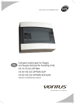
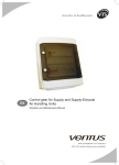
Download Control gear for Supply and Supply
Transcript
EN Control gear for Supply and Supply-Exhaust Air Handling Units Operation and Maintenance Manual DTR - CG UPC - ver.1 (10.2012) EN The control gear complies with European Standard IEC/EN 60439-1 + AC Standard Switchboards and low-voltage control gears www.vtsgroup.com Table of Content I. USER'S MANUAL ............................................................................................. 3 1. DESCRIPTION OF CONTROLS ............................................................................................................................................. 3 1.1. Introduction ........................................................................................................................................................................... 3 1.2. Mains Switch ........................................................................................................................................................................ 3 1.3. Communication port ............................................................................................................................................................. 3 1.4 Signalling controller status..................................................................................................................................................... 4 1.5. Advanced control panel VS 00 HMI ADVANCED UPC ...................................................................................................... 4 1.6. Simplified control panel - HMI BASIC UPC.......................................................................................................................... 6 WEB-server option – available as expansion card ..................................................................................................................... 7 MODBUS TCP/IP – available as expansion card ....................................................................................................................... 7 2. SYSTEM START-UP............................................................................................................................................................... 7 2.1. Switching on power supply ................................................................................................................................................... 7 2.2. HMI ADVANCED UPC ......................................................................................................................................................... 8 2.3. Language selection .............................................................................................................................................................. 9 2.4. Entering the password ......................................................................................................................................................... 9 2.5. Selection of operating mode ................................................................................................................................................ 9 2.6. Indication of operating mode ..............................................................................................................................................10 3. SYSTEM OPERATION ..........................................................................................................................................................11 3.1. PARAMETERS OPERATING MODE ..............................................................................................................................11 3.2. CALENDAR MAIN PAGE ...............................................................................................................................................11 3.2.1. CALENDAR MONDAY .................................................................................................................................................12 3.2.2. CALENDAR SPECIAL .................................................................................................................................................12 3.2.3. CALENDAR EXCEPTIONS .........................................................................................................................................12 3.3. CALENDAR MODE IN HMI BASIC ....................................................................................................................................13 3.4. PARAMETERS AIR TEMPERATURES .........................................................................................................................14 3.4.1. PARAMETERS SUP FAN & DAMPER ........................................................................................................................14 3.4.2. PARAMETERS EXH FAN & DAMPER .......................................................................................................................14 3.4.3. PARAMETERS HEATING ...........................................................................................................................................14 3.4.4. PARAMETERS RECOVERY.......................................................................................................................................15 3.4.5. PARAMETERS COOLING ..........................................................................................................................................15 3.4.6. PARAMETERS PRE-HEATING ..................................................................................................................................16 3.4.7. PARAMETERS SUP MOTORS ...................................................................................................................................16 3.4.8. PARAMETERS EXH MOTORS ..................................................................................................................................16 3.5. SETTINGS TIMERS .......................................................................................................................................................16 3.5.1. SETTINGS STANDBY .................................................................................................................................................17 3.5.2. SETTINGS NIGHT COOLING ....................................................................................................................................17 3.5.3. SETTINGS NIGHT TEST ............................................................................................................................................17 3.5.4. SETTINGS FAST HEATING........................................................................................................................................18 3.5.5. SETTINGS TEMPERATURES ....................................................................................................................................18 3.5.6. SETTINGS FANS ........................................................................................................................................................18 3.5.7. SETTINGS WATER HEATER ......................................................................................................................................19 3.5.8. SETTINGS INIT HEATING..........................................................................................................................................19 3.5.9. SETTINGS RECOVERY UNIT ................................................................................................................................... 20 3.5.10. SETTINGS DX COOLER .......................................................................................................................................... 20 3.5.11. SETTINGS WATER PRE-HEATER .......................................................................................................................... 20 3.5.12. SETTINGS INIT HEATING ........................................................................................................................................21 3.5.13. SETTINGS FAN PI REGULATOR .............................................................................................................................21 3.5.14. SETTINGS TEMP PI REGULATORS ....................................................................................................................... 22 3.5.15. SETTINGS MANUAL MODE .................................................................................................................................... 23 VTS reserves the right to implement changes without prior notice User’s Manual 1 EN 3.5.16. SETTINGS INPUT OFFSET ......................................................................................................................................24 3.5.17. SETTINGS FREQ CONV RRG ..................................................................................................................................24 3.5.18. SETTINGS FANS FIRE MODE .................................................................................................................................24 3.5.19. SETTINGS UNIVERSAL REGULATOR ....................................................................................................................24 3.6. ALARM MENU ................................................................................................................................................................... 26 ALARMING IN HMI BASIC ....................................................................................................................................................... 27 II. ADVANCED MANUAL................................................................................... 29 4. SERVICE MENU ................................................................................................................................................................... 29 4.1. SERVICE MENU CONFIG PAGES ............................................................................................................................... 29 4.2. SERVICE MENU INPUTS ............................................................................................................................................. 33 4.3. SERVICE MENU OUTPUTS ......................................................................................................................................... 33 FRQ CONVERTERS CONFIGURATION ................................................................................................................................. 34 4.4. SYSTEM INFO ................................................................................................................................................................... 35 5. CONTROL ALGORITHMS ................................................................................................................................................... 35 6. TECHNICAL DATA .............................................................................................................................................................. 38 7. CABLING .............................................................................................................................................................................. 40 Appendix 1 Circuit diagram of VS 10-75 CG UPC control gear ......................................................................................... 46 Appendix 2 Circuit diagram of VS 40-150 CG UPC SUP control gear .............................................................................. 48 EN Appendix 3 Circuit diagram of VS 40-150 CG UPC SUP-EXH control gear ..................................................................... 50 Appendix 4 Circuit diagram of VS 180-300 CG UPC control gear .................................................................................... 52 Appendix 5 Circuit diagram of VS 400-650 CG UPC control gear .................................................................................... 55 Appendix 6 Circuit diagram of power and motor connection VS 10-75 CG UPC control gears .................................... 59 Appendix 7 Circuit diagram of power and motor connection for VS 40-150 CG UPC SUP control gear .................... 59 Appendix 8 Circuit diagram of power and motor connection VS 40-150 CG UPC SUP-EXH control gear (used also for VS 180-300 supply)................................................................................................................................ 60 Appendix 9 Circuit diagram of power and motor connection for VS 180-300 CG UPC control gear (used also for VS 400-650 supply) .........................................................................................................................................61 Appendix 10 Circuit diagram of power and motor connection VS 400-650 CG UPC control gear ............................... 62 Appendix A Circuit diagram of motor connection depending on the type of the frequency converter ...................... 63 Appendix 11 The application control schemes ................................................................................................................... 63 VTS reserves the right to implement changes without prior notice 2 User’s Manual I. USER’S MANUAL 1. DESCRIPTION OF CONTROLS 1.1. INTRODUCTION Application: Protection and control of supply and exhaust AHUs equipped with up to: ○ two fan sets (up to 8 fans in total) and two air dampers ○ cooler, heater, heat recovery system ○ optional pre-heater (in specified units) ○ three filtration sections Range of operation: VS 10-75 CG UPC VS 40-150 CG UPC SUP VS 40-150 CG UPC SUP-EXH VS 180-300 CG UPC VS 400-650 CG UPC Systems equipped with frequency converters and motors with up to 11kW power output 1.2. MAINS SWITCH Function: Swithing the control gear On / Off 1.3. COMMUNICATION PORT RJ11 socket, is placed In front of the control gear housing Function: Connecting the HMI Advanced UPC control panel to the controller VTS reserves the right to implement changes without prior notice User’s Manual 3 EN 1.4. SIGNALLING CONTROLLER STATUS In the bottom left side of the controller, there are two LED indicators Orange LED indicates the condition of the power supply. LED off means no power supplied to the terminals or malfunction of internal power supply circuitry. LED on means correct parameters of the power supply. Green LED indicates the condition of controller's BIOS. LED off means that the firmware is not running correctly. LED on means that BIOS runs OK and the controller is ready for operation. 1. All control gears of the VS…CG UPC typeline need to be powered from the main switchgear equipped with appropriate protection of wires powering the control box. 2. Assembly, wiring and start-up of the control gear should by done by qualified staff only. 3. For applications subject to strong vibrations (1.5 mm pk-pk 10/55 Hz), secure the cables connected to the μPC using clamps placed around 3 cm from the connectors. EN ! 4. The entire length of the input/output connections must be less than 30 m, according to EN 61000-6-2. 5. Installation must be performed according to the standards and legislation in force in the country where the appliance is used. 6. In the event of malfunctions do not attempt to repair the controller, but rather contact the service. Without additional elements the control gears can work inside a building. Assembly outside in a moderate climate is permissible if an additional heating module is assembled. The X0:3,N clamps are designed to power that module. (ratings: 230V AC, 6A) 1.5. ADVANCED CONTROL PANEL VS 00 HMI ADVANCED UPC LCD Display Displaying available parameters, settings and current values BELL Button Jump to alarm handling pages PRG Button 1. Quick jump to the Calendar main page 2. In Calendar pages - quick clear of the settings ESC Button Jump to the main page or leaving the parameter change UP Arrow 1. Moving up accross the menu screens (when the cursor stays in upper left corner) 2. Increasing the parameter value VTS reserves the right to implement changes without prior notice 4 User’s Manual ENTER Button 1. Moving the cursor across the screen - cursor jumps to the next parameter available for changing. Read-Only parameters are not marked with the cursor. 2. Confirming entered values 3. Entering sub-menus from the main menu level: Parameters Calendar Alarms Settings Service DOWN Arrow 1. Moving down accross the menu screens (when the cursor stays in upper left corner) 2. Decreasing the parameter value EN Navigation example: 1. In the main menu level use UP/DOWN arrows to find the desired sub-menu 2. Press ENTER to go to the sub-menu level 3. Use UP/DOWN arrows to move accross the sub-menu screens 4. In the desired screen, use the ENTER button to switch between the changeable parameters - the ursor starts from the upper left corner (which is the base positnion) and jumps on and on until going back to the upper left corner - then the loop can be started again 5. To change the parameter marked with the cursor, use the UP/DOWN arrows 6. Press ENTER to go confirm the change and to jump further Functions: ▪ Air handling unit operation, parameterization and maintenance ▪ Selection of control application ▪ Time zones setting ▪ Displaying and canceling alarm statuses, viewing alarm history ! Parameters available in the LCD window depends on a AHU type and the control application. Hence in AHUs not equipped with heater, options related to the heating module will not be visible. HMI Advanced UPC can’t serve as a room temperature sensor. Optional element VTS reserves the right to implement changes without prior notice User’s Manual 5 1.6. SIMPLIFIED CONTROL PANEL - HMI BASIC UPC 1. LCD Display Indicates actual room temperature or temperature on the main control sensor as well as a chosen seting, operation mode, fan speed, time and day of the week. 2. ON/OFF button Switching between On/Off state (forcing the unit to stop or enabling operating mode selection) 3. Fan button Button for mode setting: Auto / Low / Econo / Comfort 4. Clock buttonn Entering Auto mode. Controller will operate according to the time schedule stored in Calendar settings. Note: There are two options for time schedule operation. For details, follow chapters related to Calendar and to Service Menu. EN Note: If the Calendar is also in Auto mode, the AHU operation will rely only on protective and energy saving functions like Standby and Night Cooling. This is possible for the main Calendar of the controller. The built-in Calendar of the HMI Basic doesn't support that functionality. 5. Push & Roll knob Quick, intuitive and easy entering values, changing setpoints, accepting new values. Note: To change the temperature setpoint, just turn the knob. Display of the room sensor temperature or the value of the temperature setpoint offset Note! Setting is limited to 16..26°C Icons for active recirculation, cooling or heating Time indication Display of the fan speed setting or the indication of automatic fan mode Indications of the weekdays Icon for active recovery unit Icon for alarm event Icon for Off mode VTS reserves the right to implement changes without prior notice 6 User’s Manual Functions: ▪ Room temperature measurement and display ▪ Change and display of temperature setpoint ▪ Change and display of fan setpoint ▪ Display temperature of the main control sensor ▪ Change of AHU operation mode ▪ Info on alarm status Optional element Connects to the controller via the Modbus line, common with the frequency converters. WEB-SERVER OPTION – AVAILABLE AS EXPANSION CARD MODBUS TCP/IP – AVAILABLE AS EXPANSION CARD Gives extended access to read / write parameters like measurement readouts, setpoints, settings, output values, selected calendar settings, alarms. Total count of available parameters exceeds 200 datapoints. SEE SPECIAL MANUAL FOR DETAILS OF EXPANSION CARD OPERATION 2. SYSTEM START-UP ! Operation of the AHU is strictly arrested by the fire-protection alarm, activation of the thermal protection of fans' motors, threefold activation of the protection of electric heater and threefold activation of the anti-frost thermostat. Each of these events requires removing the cause of the alarm and then canceling it ((see more details in Advanced Manual). 2.1. SWITCHING ON POWER SUPPLY Switching on power supply of the control gear with the mains switch (Q1M). Correct power supply and good BIOS operation is indicated by yellow and green LED lamps on the controller's PCB. The system is ready for operation after about half minute from switching on. If the system did not start, check the F1 protection status Correct device operation depends on the application settings. Choosing and setting up the application should be done by qualified service provider, according to recommendations of part II "Advanced manual" VTS reserves the right to implement changes without prior notice User’s Manual 7 EN 2.2. HMI ADVANCED UPC Main menu structure 1. Main default screen with most important statuses and setpoints. Set mode HMI – is used to set the main operating mode from the HMI. Current mode – indicates current AHU mode resulting from HMI setting, alarms, external control signals etc. Set temp HMI – is used to enter the main temperature setpoint from the HMI. Current temp – temperature readout from the main sensor. 2. Second main status screen Fans – indicates the current state and rate of the fans Dampers – indicates the current state and opening rate of the dampers Regulator – indicates the state and the output of the main controller for heating / cooling function EN Recovery – indicates the state and rate of the heat recovery unit EN/PL/RU – language selection PASSWORD – is used to enter to special settings and hidden parameters 3. Sub-menu link screen PARAMETERS link to main statuses and readouts from the control system 4. Sub-menu link screen CALENDAR link to calendar settings and time schedule programming 5. Sub-menu link screen ALARMS link to alarm pages 6. Sub-menu link screen SETTINGS link to set and adjust the control system, regulators, timers 7. Sub-menu link screen SERVICE MENU link to main configuration parameters, application codes, AHU startup settings All the menus are dynamically changed, as they depend on the application settings and the password level VTS reserves the right to implement changes without prior notice 8 User’s Manual 2.3. LANGUAGE SELECTION HMI Advanced supports the following languages: EN English PL Polish RU Russian English is set as a default language. 2.4. ENTERING THE PASSWORD Many parameters are protected with a password, to avoid unintentional change, that could be dangerous for the unit or for the user. To access that parts of the menu, a password must be entered. Default password is: 1357 2.5. SELECTION OF OPERATING MODE The AHU can operate in one of the following operating HMI ADVANCED modes. Selection path: Main menu / Set mode HMI / Auto – AHU operates depending on – the calendar Auto..Off..Low..Econo..Comfort programming HMI Basic Set mode HMI Comfort external control signals (binary inputs) Current mode InitHtg Set temp HMI 21,0°C critical temperatures, e.g. too low temperature causes AHU start and immediate heat-up of the room Current temp 19,4°C Off - AHU switched off – fans stopped, dampers and control valves closed Mon 28.02.2011 10:09 all sensors and gauges are activated – in order to protect the unit from damage, e.g. fire alarm, frost protections Low – Lower economy mode – The fan speed and the deadzone for temperature regulation are adjustable The temperature control algorhitm can use broad deadzone and the fans can be set to low speed in order to reduce energy consumption Econo – Upper economy mode – The fan speed and the deadzone for temperature regulation are adjustable The temperature control algorhitm can use narrower deadzone and the fans can be set to higher speed in order to optimize energy consumption Comfort – Comfort mode – The fan speed and the deadzone for temperature regulation are adjustable The temperature control algorhitm can use most accurate deadzone and the fans can be set to highest speed in order to give maximum comfort Note! The temperature setpoint is common for all operating modes, the deadzone settings are individual for each mode. HMI BASIC 1. On/Off button - press to switch between Off and Low mode. 2. Fan button - press to switch operating mode between Low - Econo - Comfort 3. Clock button - press shortly to switch to Auto mode. In Auto mode Calendar will be capable of taking over the control. VTS reserves the right to implement changes without prior notice User’s Manual 9 EN 2.6. INDICATION OF OPERATING MODE The following modes can be displayed in Current mode field in the main menu: Auto..Off..Low.. Econo..Comfort as described above Fire – operating mode enabled by fire alarm input. All the devices switched off, the fans stop or run with selected setpoint (see chapter Service Menu) OverRun – AHU switches off, but the fans keep running on the idle speed until the heater is cooled down (see chapter Service Menu) NightClg – Night Cooling – a mode for energy saving by cooling down the room using cold air from the outside in the night. Available only in the units with external temperature sensor. Standby – protection mode for min/max room temperature – if the temperature exceeds specified setpoints, AHU is switched on, to heat up or cool down to desired range. Then switches off again. NightKick – testing mode, that forces fans to run in order to exchange the air in the ventilation system. Note! Night cooling and Standby functions rely on room temperature. If there’s no measurement in the room, the exhaust duct sensor is taken into account and gives the readout. This requires turning on the fans to have appropriate room temperature value on that sensor. EN InitHtg - Initial Heating - a mode for startup of water heating units in winter conditions, heats up the coil before starting the fans in order to prevent activation of frost alarms. Startup - temporary mode when dampers are opening, fans speed up and the heating / cooling devices are enabled and start operation. FastHtg / FastClg - Fast Heating or Cooling - special mode for units with PCR or RRG recovery, that allows operation with closed intake/outlet dampers and full recirculation. That improves heating up the building. Heating - mode when heaters can be enabled Cooling - mode when coolers can be enabled Vent - Ventilation - energy saving mode, when neither heaters nor coolers are enabled and the unit operates only with ventilation and optional recovery unit. EmgStop - Emargency Stop - unit forced to stop immediately, according to signal from optional digital input. AlrStop - Alarm Stop - unit forced to stop because of an alarm CrtStop - Critical Stop - unit forced to stop because of a critical alarm Config - unit forced to stop because the controller is in Config mode. Conatoller must be configured first and switched to Running mode The unit can be controlled from several sources. Mind the priorities between them. 1. HMI Advanced (highest priority) 2. The BMS over Modbus TCP/IP connection 3. External control inputs 4. HMI Basic 5. The calendar mode Note! To enable another sources than the HMI Advanced, the Operating mode HMI must be set to Auto VTS reserves the right to implement changes without prior notice 10 User’s Manual 3. SYSTEM OPERATION 3.1. PARAMETERS OPERATING MODE Actual – indicates current AHU mode resulting from HMI setting, HMI ADVANCED alarms, external control signals etc. OPERATING MODE From HMI – indication of the operating mode from the HMI From BMS – indication of the operating mode requested from BMS link over the Modbus TCP/IP connection HMI Advanced Note! Control over Modbus TCP/IP is available only in controllers BMS equipped with expansion board Digital inputs External ctrl – indication of the operating mode resulting from HMI Basic the digital inputs Calendar HMI Basic - indication of the operating mode resulting from the HMI Basic UPC device DI Sum From Calendar – indication of the operating mode from the calendar Actual season – selection of the current working mode for HMI ADVANCED universal heating/cooling coil. If “Winter” selected – the coil works as a water heater. If “Summer” selected – the coil works OPERATING MODE as a water cooler. Selection HMI – Winter/Summer Actual season Binary input – Winter/Summer – universal binary input can be configured as a season selector Selection HMI From BMS – indication of the operating mode requested from Binary input BMS link over the Modbus TCP/IP connection From BMS Sum/Wint – season selection switch – used in combi-coil applications, where one coil can be switched to heating in winter (fed from boiler) or to cooling in summer (fed from chiller). The selected season must correspond to the actual setup of the hydraulic valves. Note! The pipeline has to be switched manually between supplying from chiller or from boiler. The season selection must be done according to the actual state of the piping. Note! The Summer mode has got lower priority than the Winter mode, regardless to the control source – HMI or binary input or BMS command over Modbus TC/IP connection. Comfort Auto Auto Auto Auto HMI Wint Winter Winter Summer Winter 3.2. CALENDAR MAIN PAGE HMI ADVANCED CHECK FOR ERRORS! - indicates misordered settings. That text is displayed in the top line only if errors were found in the CALENDAR calendar settings. CHECK FOR ERRORS! Calendar mode – indicates current mode from calendar: Auto.. Off..Low..Econo..Comfort Calendar mode Standby Temp setpoint – indicates current temperature setpoint from Temp.setpoint 21,0°C calendar Exceptions Disabled Exceptions – indicates if the special time zones were activated or not: Disabled..Enabled Date Mon 28.02.2011 Date – indicates the current date and weekday, allows for change Time 10:09 Time – indicates current time, allows for change VTS reserves the right to implement changes without prior notice User’s Manual 11 EN 3.2.1. CALENDAR MONDAY HMI ADVANCED Clr – quick erase of all the daily settings – press PRG button to activate, ESC to quit or ENTER to go to further settings CALENDAR MONDAY 1 00:00 Off 21,0°C ! / OK – indicates the right order of time zones, zone 1 is the earliest, zone 6 is the latest, and all zones should be in ascending order 2 05:20 Stby 21,0°C 3 06:00 Low 22,5°C 4 12:30 Econo 22,5°C Lines 1..6 – six time zones for daily settings 5 14:00 Comfort 22,5°C Time – starting point for the zone, range 00:00..23:59, first zone start fixed at 00:00, last zone end fixed at 23:59 6 19:00 Stby 19,0°C Clear OK Operating mode – Auto..Off..Low..Econo..Comfort Temperature setpoint – individual temperature setpoint for each time zone EN The same range of settings applies to all days of the week. Each day has own page in the Calendar. 3.2.2. CALENDAR SPECIAL HMI ADVANCED Copy Mon – Fri – copy the settings from Monday to all working days Copy Mon – Sun – copy the settings from Monday to all days of the week Select desired option with ENTER key and press PRG to activate. CALENDAR Special Copy Mon-Fri Copy Copy Mon-Sun Copy 3.2.3. CALENDAR EXCEPTIONS HMI ADVANCED There are six exception settings for specific periods like holidays. Activate – No..Yes – activates the exception settings From – starting point for the period (month, day, time) To – end point for the period (month, day, time) Mode / Setpoint – set desired operating mode and temperature setpoint EXCEPTIONS Activate Yes From 01.03 00:00 To 06:03 12:00 Mode Setpoint Off 21,0°C VTS reserves the right to implement changes without prior notice 12 User’s Manual 3.3. CALENDAR MODE IN HMI BASIC HMI Basic can operate with time schedules in two ways. Selection is done in Service Menu of the μPC controller and is available only via HMI Advanced interface. HMI BASIC 1. HMI Basic can use the calendar in the controller – all settings are done via HMI Advanced or via BMS connection and HMI Basic can only activate / deactivate operation according to time schedule stored in the controller. Note! HMI Basic cannot change any settings in the controller's calendar. 2. HMI Basic can use own local time scheduler – all the settings are done and stored in HMI Basic. Note! Mind the limitations of the HMI's calendar – only On/ Off and temperature settings can be adjusted in the HMI Basic. Low / Econo / Comfort modes must be pre-set in the controller settings via HMI Advanced. EN Setting the program for selected days: 1. Clock button - long-press to enter settings mode 2. Turn the knob to select "Time band" and press to enter 3. In "Sel days" turn the knob to select days - whole week, working days, weekend, or any day separately. Then press to enter. 4. Observe the house icon - it indicates which time zone is edited at the moment. Turn the knob to select specific time zone from 1 to 6. Press to enter. 5. Turn the knob to set hour and press to confirm. Note! Between 23 and 00 there's blank setting --:-- which means, that current time zone is skipped. 6. Turn the knob to set minutes and press to confirm. 7. Turn the knob to set the temperature adn press to confirm. Note! Below min. setpoint there's OFF setting. Use that to turn off the unit in selected time zone. To leave from any level of calendar programming, select ESC and press to confirm. To set clock, long-press the Clock button to enter settings mode, turn the knob to select Cloc, press to enter and set proper hour, minutes and weekday. Note! Setting the weekday properly is necessary for correct operation of the Calendar mode. VTS reserves the right to implement changes without prior notice User’s Manual 13 3.4. PARAMETERS AIR TEMPERATURES HMI ADVANCED AIR TEMPERATURES Supply Readout of actual temperature inputs. If the sensor is not activated in the application, indicates "-". Room 21,0°C 21,0°C Exhaust 21,0°C External 21,0°C After recovery 21,0°C Pre-heater 21,0°C 3.4.1. PARAMETERS SUP FAN & DAMPER 3.4.2. PARAMETERS EXH FAN & DAMPER EN Sup fan setpoint / Exh fan setpoint – setting for fan rate given in % for Low / Econo / Comfort separately Sup fan rate / Exh fan rate – indicate the current fan state by showing the percentage of control signal. 0% = fans stopped, >0% = fans running Status - combined information for communication problems and for motor alarms OK - no malfunctions Comm - communication to the frequency converter not stable or lost Alarm - communication OK, but frequency converter reported an error, e.g. overload Damper opening - indicates current position of the intake and outlet dampers: 0% = fully closed, 100% = fully opened Note! The fan rate settings cannot exceed Freq. low / high limit settings. If so, they are corrected automatically. HMI ADVANCED SUP FAN & DAMPER Sup fan setpoint Low: 30% Eco: 60% Comf: 90% Sup fan rate 60% Alarm status OK Damper opening 100% 3.4.3. PARAMETERS HEATING Main temp – current readout from the main temperature HMI ADVANCED sensor HEATING Setpoing – current setpoint for the regulator, read only Main temp Heating rate – indicates current heating capacity Setpoint 0% – no heating, 100% – full heating Heating rate Pump status – indicates current state of the circulation pump Pump status On - turned on Alarm status Off - switched off Back-water Alarm status – indicate the state of frost protection input or overheating protection (for water coil or electrical heater, respectively) Back water – current readout of the back-water temperature measured on outlet pipe of the heating coil. 18,0°C 21,0°C 40% On OK 50,0°C VTS reserves the right to implement changes without prior notice 14 User’s Manual 3.4.4. PARAMETERS RECOVERY Recovery mode - selecting the operation mode for the recirculation chamber • MECH – Maximum Energy Changeover – control from the PID controller, recirculation plays the role of the first heating / cooling section in order to take full advantage of energy recovery, the scope of possible changes concerning recirculation is defined by fixed setting of minimum fresh air. • Manual - fixed manual recirculation settings • Univ.AI – control from the universal analog input; the range of possible changes is limited by the setting of minimum fresh air Recovery rate – indicates current recovery capacity, gives a link to output detail screen (password protected link – see Advanced Manual) 0% – no recovery, 100% – full recovery Note! The controller signal can differ from the actual recovery rate due to protective functions that could affect it. Frost prot. rate – indicates the rate of frost protection, that is subtracted from controller signal in order to protect the recovery unit from freezing Note! Frost protection can be managed in two stages - first step can be reduction of supply fan speed, second step is reducing the recovery rate Glycol pump – indicates current state of the pump, gives a link to pump detail screen (see Advanced manual) Status - combined information for communication problems and for motor alarms OK - no malfunctions Comm - communication to the frequency converter not stable or lost Alarm - communication OK, but frequency converter reported an error, e.g. overload HMI ADVANCED RECOVERY Recov. mode MECH Recovery rate 50% Frost prot.rate o% Glycol pump On Alarm status OK EN 3.4.5. PARAMETERS COOLING HMI ADVANCED Main temp – current readout from the main temperature sensor Setpoint – current setpoint for the regulator, read only Cooling rate – indicates current cooling capacity 0% – no cooling, 100% – full cooling Pump status – indicates the current state of the pump or chiller Alarm status – indicates the state of the cooling device OK – no malfunctions Fault – alarm input has been activated COOLING Main temp Setpoint Cooling rate 27,0°C 21,0°C 65% Pump status On Alarm status OK VTS reserves the right to implement changes without prior notice User’s Manual 15 3.4.6. PARAMETERS PRE-HEATING Temperature – current readout from sensor dedicated for pre-heating coil Setpoint – current setpoint for the regulator, read only Heating rate – indicates current heating capacity 0% – no heating, 100% – full heating Pump status – indicates current state of the circulation pump Alarm status – indicate the state of frost protection input Note! The pre-heating coil works out of the standard cooling/heating sequence. It is intended just to keep the constant temperature in specified place, e.g. to heat up outside air before entering the heat recovery unit. HMI ADVANCED PRE-HEATING Temperature -10,0°C Setpoint Heating rate -11,0°C 40% Pump status On Alarm status OK 20,0°C Back-water 3.4.7. PARAMETERS SUP MOTORS 3.4.8. PARAMETERS EXH MOTORS EN HMI ADVANCED Freq - actual output frequency Current - actual current consumption SUP MOTORS Status - combined information for communication problems Freq Current and for motor alarms 1: 40,0Hz 4,1A OK - no malfunctions 2: 40,0Hz 4,3A Comm - communication to the frequency converter not 3: 40,0Hz 4,2A stable or lost 4: 40,0Hz 4,2A Alarm - communication OK, but frequency converter reported an error, e.g. overload Note! Ventus AHU can have up to 4 frequency converters in one fan set (MultiFan configuration). All FCs in the fan set have common settings for frequency, ramp-up, ramp-down and the main limits – as they must work synchronously. Note! FC details visible only if frequency converters were enabled during unit configuration Status OK OK OK OK 3.5. SETTINGS TIMERS On-delay - setting for startup delay, from start command to the actual startup of the unit Idle - setting for startup procedure, in idle state the fans run at lowest speed, dampers are opening and all the heating/ cooling/recovery and protective regulators enter normal operation mode Off-delay - setting for delayed stopping of the fans, can be used to cool down electric heater or to run down the DX cooling system HMI ADVANCED TIMERS Sup Exh On-delay 20s 10s Idle 20s 30s Off-delay 10s 10s VTS reserves the right to implement changes without prior notice 16 User’s Manual 3.5.1. SETTINGS STANDBY Enable – activate the standby functionality No – function disabled Yes – function enabled Start Htg – temperature at which the heating is activated Setpoint Htg – temperature at which the heating is turned off Start Clg – temperature at which the cooling is activated Setpoint Clg – temperature at which the cooling is turned off Min work time – min. running time in standby mode Min delay – min. resting time after working in standby mode HMI ADVANCED STANDBY Enable Start Htg Yes Setpoing Htg 16,0°C 22,0°C Start Clg 27,0°C Setpoing Clg 18,0°C 60s Min work time Min delay 600s 3.5.2. SETTINGS NIGHT COOLING Enable – activate the night cooling functionality No – function disabled Yes – function enabled Min ext temp – night cooling function is disabled below that limit of external temperature Min work time – min. working time for the nigh cooling Min delay - min. time when the function cannot be enabled again HMI ADVANCED EN NIGHT COOLING Enable Min ext temp Min work time Min delay Yes 18,0°C 60s 60s 3.5.3. SETTINGS NIGHT TEST HMI ADVANCED Night cooling and Standby functions rely on room temperature. If there’s no temperature measurement in NIGHT TEST the room, the exhaust duct sensor is taken into account Enable and gives the readout. This requires turning on the fans to refresh the air and have appropriate room temperature Test hour value on that sensor. Test duration Enable – activate the night test functionality No – function disabled Yes – function enabled Test hour – setting the time, when the night test function will be triggered. The night test operates in a daily manner. Test duration – specifies how long the night test will be executed Note! If during the Night Test operation, conditions for Night Cooling or Standby will be detected, the unit will automatically switch to another relevant mode. Note! Night Test functionality will not be triggered if external temperature is lower than Min Ext Temp for Night Cooling. Yes 05:15 60s VTS reserves the right to implement changes without prior notice User’s Manual 17 3.5.4. SETTINGS FAST HEATING Enable – activate the fast heating functionality No – function disabled Yes – function enabled Temp deviation – the fast heating algorithm will be executed until the main temperature is lower than the setpoint by the value of Temp deviation HMI ADVANCED FAST HEATING Enable Temp deviation Yes 5,0°C 3.5.5. SETTINGS TEMPERATURES EN Setpoint Hi – setting for upper boundary of temperature setpoint Range: 20..40 Default: 26 Setpoint Lo – setting for lower boundary of temperature setpoint Range: 0..20 Default: 16 Deadzone LOW – settings for the allowed non-sensitive range in Low mode Range: 0..10 Default: 4.0 Deadzone ECO – settings for the allowed non-sensitive range in Econo mode Range: 0..10 Default: 2.0 Deadzone COMF – settings for the allowed non-sensitive range in Comfort mode Range: 0..10 Default: 1.0 Min Clg temp – setting for the temperature limit. If external temperature falls below that value, the cooling functionality is disabled. Range: 0..20 Default: 16 HMI ADVANCED TEMPERATURES Setpoint Hi 26,0°C Setpoint Lo 16,0°C Deadzone LOW 4,0°C Deadzone ECO 2,0°C 1,0°C Deadzone COMF Min Clg temp 16,0°C 3.5.6. SETTINGS FANS Supply freq limits Min / Max Exhaust freq limits Min / Max Limits in Hz for allowed range of operation Ramp up / Ramp down – settings for acceleration and deleceleration times Range: 30..120s Default: 45s Note! The fan rate settings cannot exceed Freq. low / high limit settings. If so, they are corrected automatically. HMI ADVANCED FANS Supply freq limits Min: 20Hz Max: 80Hz Exhaust freq limits Min: 20Hz Max: 80Hz Ramp up 45s Ramp down 45s VTS reserves the right to implement changes without prior notice 18 User’s Manual 3.5.7. SETTINGS WATER HEATER Pump start temp – setting for the temperature limit, that forces the pump to continuous operation for initial freezing protection Range: -10..20 Default: 5 Pump kick – timer that forces the circulation pump to run for short period of time (30s) in specified intervals. That prevents the mechanical sealings from sticking and damage. Range: No - function disabled Day - function activated daily Week - weekly Month - monthly Back water setp – setpoint for back water temperature regulator. Special PI regulator works in two operating modes. First is normal heating mode, when the AHU is working. Regulator prevents the back water from dropping below the temperature limit. Note! Main temperature has got lower priority than backwater control! Second mode is anti-freezing protection, when the AHU is stopped in Off mode. The regulator maintains the back water temperature equal to the setpoint value, in order to prevent returning too hot water to the boiler system. Note! Back-water control functionality is optional and must be enabled in Configuration mode of the controller. HMI ADVANCED WATER HEATER 5,0°C Pump start temp Pump kick Day 40,0°C Back-water setp EN 3.5.8. SETTINGS INIT HEATING HMI ADVANCED INIT HEATING HW T1 – lower scaling external temperature T2 – upper scaling external temperature Y1 – heating rate at T1 temperature Y2 – heating rate at T2 temperature t_a - time to force the valve to 100% opening, regardless to the external temperature, in order to fill the pipeline with the hot water t_b – time the unit stays with calculated heating rate Note! Total time is t_a + t_b . These settings are common for initial heating of pre-heater and secondary heater, if both are present in the AHU. Y2 75% Y1 25% T1 -25°C t_a 30s t_b 60s T2 5°C VTS reserves the right to implement changes without prior notice User’s Manual 19 3.5.9. SETTINGS RECOVERY UNIT After reco setp - setpoint for minimal allowed temperature after the recovery units PCR, RRG or glycol turnaround coils Range: -64..64 Default: 3.0 Min. fresh air – setting for min. opening of intake / outlet dampers to provide fresh air in the ventilated room Range: 0..100% Default: 30% Manual mode - setting fixed values of recirculation for Hand and Hand.Multi modes Range: 0 ….. 100% Default: 30% HMI ADVANCED RECOVERY UNIT After reco setp Min fresh air Low: 30% Eco: 30% Comf: 30% Eco: 30% Comf: 30% Manual setting Low: 30% 3.5.10. SETTINGS DX COOLER EN HMI ADVANCED On / Off for stage I and for stage II - settings for the relation between coolind regulator and DX unit stages DX COOLER Min work – setting for the min. working time for each stage Range: 10..600s On Default: 30s Off Min rest – setting for the min. resting time for each stage Min work Range: 10..600s Min rest Default: 30s st.I st.II 30% 60% 10% 40% 25s 25s 60s 60s 3.5.11. SETTINGS WATER PRE-HEATER Pump start temp – setting for the temperature limit, that forces the pump to continuous operation for initial freezing protection Range: -10..20 Default: 5 Pump kick – timer that forces the circulation pump to run for short period of time (30s) in specified intervals. That prevents the mechanical sealings from sticking and damage. Range: No - function disabled Day - function activated daily Week - weekly Month - monthly Back water setp – setpoint for back water temperature regulator. Special PI regulator works in two operating modes. First is normal heating mode, when the AHU is working. Regulator prevents the back water from dropping below the temperature limit. Note! Main temperature has got lower priority than backwater control! HMI ADVANCED WATER PRE-HEATER Pump start temp Pump kick Back-water setp 5,0°C Day 40,0°C VTS reserves the right to implement changes without prior notice 20 User’s Manual Second mode is anti-freezing protection, when the AHU is stopped in Off mode. The regulator maintains the back water temperature equal to the setpoint value, in order to prevent returning too hot water to the boiler system. Note! Back-water control functionality is optional and must be enabled in Configuration mode of the controller. Note! The pre-heating coil works out of the standard cooling/ heating sequence. It is intended just to keep the constant temperature in specified place, e.g. to heat up outside air before entering the heat recovery unit. 3.5.12. SETTINGS INIT HEATING T1 – lower scaling external temperature HMI ADVANCED T2 – upper scaling external temperature INIT HEATING PRE-HW Y1 – heating rate at T1 temperature Y2 50% Y2 – heating rate at T2 temperature Y1 20% T1 -40°C t_a - time to force the valve to 100% opening, regardless to t_a 30s t_b 60s the external temperature, in order to fill the pipeline with the hot water t_b – time the unit stays with calculated heating rate Note! Total time is t_a + t_b . These settings are common for initial heating of pre-heater and secondary heater, if both are present in the AHU. T2 -10°C EN 3.5.13. SETTINGS FAN PI REGULATOR Recovery frost protect - special PI regulator to manage supply fan speed reduction in case of freezing conditions. If the limit temperature is reached, the regulator reduces the frequency converter output by specified max. value in Hz Kp - proportional gain Ti - integrational time Ymin - min. value of subtracted frequency (no frost protecting action) - fixed at 0Hz Ymax - max. value of subtracted frequency (max. frost protecting action) Range: 0..50Hz Default: 5Hz HMI ADVANCED FAN PI REGULATORS Recovery frost protect Kp Ymin HMI ADVANCED Parametric volume control – special regulator for automatic adjustment of the fan speed according to external FAN PI REGULATORS measurement of flow or pressure. The input Parametric volume control Kp - proportional gain Kp Ti - integrational time Ymin Ymin - min. value – fixed at min fan rate setting Setpoints Ymax - max. value – limited by fan rate setpoint for current Low Eco mode Low / Econo / Comfort Setpoints Low / Econo / Comfort – setpoints for each mode Ti Ymax Ti Ymax Comf VTS reserves the right to implement changes without prior notice User’s Manual 21 3.5.14. SETTINGS TEMP PI REGULATORS There are alltogether 9 regulators for temperature control. Mostly all of them allow for the same adjustments: Kp - proportional gain Ti - integrational time Ymin - min. value ofr the output Ymax - max. value of the output The regulators are: Min sup temp – regulator of min. supply temperature limit Max sup temp – regulator of max. supply temperature limit HMI ADVANCED TEMP PI REGULATORS Min sup temp Kp Ti Ymin Ymax Max sup temp Kp Ti Ymin Ymax HMI ADVANCED TEMP PI REGULATORS Heating – regulator for main heater Back water – regulator for limiting return water temperature in heater protective mode in stopped AHU EN Heating Kp Ti Ymin Ymax Back-water Kp Ti Ymin Ymax HMI ADVANCED TEMP PI REGULATORS Pre-Heating Pre-heating + Back water – regulators for pre-heater, identical to those for standard heater Kp Ti Ymin Ymax Back-water Ti Kp Ymin Ymax HMI ADVANCED TEMP PI REGULATORS Recovery – regulator for recovery unit Frost protection – regulator for recovery unit protection in winter conditions Recovery Ti Kp Ymin Ymax Frost protection Ti Kp Ymin Ymax HMI ADVANCED TEMP PI REGULATORS Cooling – regulator for cooler Cooling Kp Ymin Ti Ymax VTS reserves the right to implement changes without prior notice 22 User’s Manual 3.5.15. SETTINGS MANUAL MODE HMI ADVANCED Manual operation – override the inputs and output Auto – cancel override other states – select to force the inputs or outputs, values depend on the output type DI1..DI7 - digital inputs - select Auto / On / Off Note! For states different from NULL, an alarm is triggered, the HMI operating mode is forced to Off and AHU cannot be started. Manual mode is intended only for testing purposes. Note! For any overridden states, an alarm is triggered, the HMI operating mode is forced to Off and AHU cannot be started. Manual mode is intended only for testing purposes. Always observe the unit for unintended unsafe operation when using manual mode! MANUAL MODE DI1 DI2 DI3 Auto On Off DI4 DI5 DI6 Auto Auto Auto DI7 Auto HMI ADVANCED EN MANUAL MODE B1..B7 - temperature probe inputs - select Auto / -20 / -10 / 0 / 10 / 20 / 30 B1 B2 B3 Auto -20 -10 B4 B5 B6 Auto Auto NO1 NO2 NO3 Auto On Off NO4 NO5 NO6 Auto Auto Auto Y1 Y2 Y3 Auto 0% 20% Auto B7 Auto HMI ADVANCED MANUAL MODE NO1..NO7 - digital outputs - select Auto / On / Off NO7/NC7 Auto HMI ADVANCED Y1..Y3 - analog outputs - select Auto / 0 / 20 / 40 / 60 / 80 / 100 MANUAL MODE VTS reserves the right to implement changes without prior notice User’s Manual 23 3.5.16. SETTINGS INPUT OFFSET HMI ADVANCED Offset to correct the stable additive error, e.g. from very long sensor cable INPUT OFFSET B1 B2 B3 B4 B5 B6 B7 3.5.17. SETTINGS FREQ CONV RRG EN Freq - actual output frequency HMI ADVANCED Current - actual current consumption RRG DRIVE Status - combined information for communication problems Freq and for motor alarms 45Hz OK - no malfunctions Min frequency Comm - communication to the frequency converter not Max frequency stable or lost Alarm - communication OK, but frequency converter reported an error, e.g. overload Freq. low limit – lower boundary of the frequency Range: 10..25Hz Default: 15Hz Freq. high limit – upper boundary of the frequency Range: 35..65Hz Default: 55Hz Current Status 0,6A OK 15Hz 55Hz 3.5.18. SETTINGS FANS FIRE MODE Settings for the fan behavior when there’s a fire alarm signal Sup fire setp - 0..100% - setpoint for fan rate in fire conditions, 0% = fan stopped Exh fire setp - 0..100% - setpoint for fan rate in fire conditions, 0% = fan stopped Fire temp limit - setpoint for the supply and exhaust duct temperature that triggers the alarm signal Range: 60..99 Default: 99 HMI ADVANCED FANS FIRE MODE Sup fire setp Exh fire setp Fire temp limit 3.5.19. SETTINGS UNIVERSAL REGULATOR The universal controller allows the use to implement some specific functionalities, that are not supported by original Ventus applications. The structure of the universal controller contains of two main blocks: comparator – to check the relation between two signals (can be selected from the program variables or from universal analog input) HMI ADVANCED VTS reserves the right to implement changes without prior notice 24 User’s Manual logic block – the output from the comparator can be processed by a logic function with another binary value (from the program or from the binary input) the binary output – can do simple on/off control to external actuators via universal relay 1 or 2 44 < 50 AND Off = Off – current status line, shows all Input values, all functions and resulting output Signal source – select signal source to be compared with a reference in comparator block AI7 – user configurable analog input SupplyTmp – supply temperature [°C] RoomTmp – room temperature [°C] ExhustTmp – exhaust temperature [°C] RecovrTmp – temperature after the heat recovery unit [°C] ExternTmp – external temperature [°C] HeatgRate – heating rate [%] CoolgRate – cooling rate [%] RecovRate – heat recovery rate [%] SupFnRate – supply fan rate [%] ExhFanRate – exhaust fan rate [%] Compare function – type of compare action Less – check if the source signal is less than the reference Greater Equal True – forces constant logical TRUE on comparator’s output False – forces constant logical FALSE on comparator’s output UNIV REGULATOR 44 < 50 AND Off = Off Signal src AI7 Compare func Less Setpoint src Const: Logic block Logic source AI7 Hyst: AND DI6 Setpoint source – select the reference for comparator AI7 – user configurable analog input Constant – constant value set in following line Setpoint constant Range: -100..100 Default: 20 Hysteresis – set the hysteresis for comparator Range:0..100 Default: 1.0 Logic Block – select type of logical operation AND NAND OR NOR XOR VTS reserves the right to implement changes without prior notice User’s Manual 25 EN Logic source – select logic signal source DI6 – user configurable digital input 2 DI7 – user configurable digital input 1 StartConf – start confirmation HeatgConf – heating confirmation CoolgConf – cooling confirmation RecovConf – heat recovery confirmation InAlarm – AHU in alarm True – constant TRUE False – constant FALSE EXAMPLE 1 – Additional roof exhaust fan EN Requested functionality: if supply fans run at more than 70% setpoint, turn on additional fan Additional condition: additional fan’s thermal protection is OK – multi-function digital input 1 is HIGH Settings for universal controller: Signal source ▪ SupFnRate Compare function ▪ Greater Setpoint source ▪ Constant Setpoint constant ▪ 70% Hysteresis ▪1 Logic Block ▪ AND Logic source ▪ DI7 Note! The universal relay REL3 or REL6 must be set to UniReg or NOTUniReg – to let the resulting signal out of the controller. HMI ADVANCED UNIV REGULATOR 59 < 70 AND On = Off Signal src SupFnRate Compare func Greater Setpoint src Const: 70 Logic block Logic source Constant Hyst: 1 AND DI7 3.6. ALARM MENU ALARM MENU Alarm menu can be accessed via dedicated button on the HMI Advanced NAME – description of the feature or function that was in alarm state, e.g. Modbus comm STATUS – current condition of the alarm, OK – inactive, ALARM – active HMI ADVANCED VTS reserves the right to implement changes without prior notice 26 User’s Manual TYPE – defines the group of alarm events – Normal – these are mostly non-remanent alarms of lower priority; Critical – these are mostly remanent alarms of higher priority, that could even stop and block the unit from further operating. DATE / TIME – time stamp when the alarm occured Note! To acknowledge the alarm currently displayed on the HMI, press PRG button. Another way of cancelling the alarms is turning the power Off and On again. At startup all alarms are cleared, except of those, that are stiil activated by input signals. Note! Alarms can be remanent – they are locked until fixed and acknowledged, e.g. the fire alarm. Or can be nonremanent – they unlock, when the alarm signal is fixed and don’t need to be acknowledged to go to the history records, e.g. the filter alarm. ALARMS NAME STATUS Fire alarm ALARM TYPE Critical DATE 05.07.11 TIME 10:11 ALARMING IN HMI BASIC Alarm in HMI Basic are displayed instead of time indication in a form of a letter and number, like AL15. The number is given to identify what is the source of alarm. Note! HMI Basic cannot acknowledge alarms. All nonremanent events will disappear automatically. All remanent events need to be reset by means of HMI Advanced, or by switching off / on the power supply. List of alarm codes: AL01. Fire alarm AL02. HW thermostat AL03. HW back-water AL04. Pre-HW thermost AL05. Pre-HW back-wtr AL06. HE overheat AL07. Supply sensor AL08. Exhaust sensor AL09. Room sensor AL10. Aft.Reco sensor AL11. External sensor AL12. HW water sensor AL13. Pre-HW sensor AL14. Pre-HW wtr.sens AL15. SupFan1 comm AL16. SupFan2 comm AL17. SupFan3 comm AL18. SupFan4 comm AL19. SupFan1 ovrload HMI BASIC VTS reserves the right to implement changes without prior notice User’s Manual 27 EN EN AL20. SupFan2 ovrload AL21. SupFan3 ovrload AL22. SupFan4 ovrload AL23. ExhFan1 comm AL24. ExhFan2 comm AL25. ExhFan3 comm AL26. ExhFan4 comm AL27. ExhFan1 ovrload AL28. ExhFan2 ovrload AL29. ExhFan3 ovrload AL30. ExhFan4 ovrload AL31. Manual mode AL32. HMI Basic init AL33. HMI Basic comm AL34. HMI Adv.init AL35. HMI Adv.comm AL36. Modbus init AL37. Modbus comm AL38. BMS init AL39. BMS comm AL40. Chiller AL41. Sup filters AL42. Exh filters VTS reserves the right to implement changes without prior notice 28 User’s Manual II. ADVANCED MANUAL 4. SERVICE MENU Service menu is intended for service use, mainly at general startup of the AHU. The whole menu is password protected and cannot be even viewed without logging-in. Configuration of the controller is the most important startup action, that influences the whole behavior of the controlled air handling unit. All the functionalities, like specific heaters or frequency converter types, are selected here. If not done properly, the controller will apply control algorithms not efficient and in worst case dangerous to the equipment. 4.1. SERVICE MENU CONFIG PAGES APPLICATION CODE ERROR – is a warning displayed in the HMI ADVANCED top line of the page, if the application code data is bad. If the CONFIG code is OK, nothing is displayed. Program mode – setting whether the controller is in configuration or in normal working mode ▪ Config (default factory state) ▪ Running APPLICATION CODE ERROR Program mode Application Main sensor Note! The controller mode must be switched from Config to Running after completing all the settings in unit configuration and in frequency converters configuration pages. Config Unit size HMI Basic VS10-15 AD 0000 Supply NO Unit size – setting for small units with reduced application set or for fully featured units ▪ VS10-15 – for VS10-15 units ▪ VS21-650 – for VS21-650 units Application – setting for the application code, done in two parts – the letter code, defining base features of the unit and the number code, defining detailed configuration of the AHU ▪ AD – for supply-exhaust units (default) ▪ AG – for S-E units with glycol heat recovery ▪ AP – for S-E units with plate cross-flow recuperator ▪ AR – for S-E units with rotary regenerator The number code – range 0..1024 ▪ Default: 0 Main sensor – setting for the temperature controllers. The signal from chosen sensor is compared to the reference for heating / cooling / recovery actions ▪ Supply (default) ▪ Room ▪ Exhaust VTS reserves the right to implement changes without prior notice Advanced manual 29 EN HMI Basic – setting for enabling the HMI Basic communication • NO - control system without HMI Basic • ITS - control system with HMI Basic, the interface screen indicates the real room temperature measured with its own sensor (Internal Temperature Sensor mode). • MTS - control sstem with HMI Basic, the interface screen indicates the temperature value measured by the main sensor (Main Temperature Sensor mode). • ITS+Cal - Internal Temperature Sensor mode + calendar operation according to internal scheduler of the HMI Basic • MTS+Cal – Main Temperature Sensor mode + calendar operation according to internal scheduler of the HMI Basic EN Supply FC – selection of the frequency converter type for supply side Exhaust FC – selection for the exhaust side • No FC – no frequency converters, the Modbus communication is disabled and don’t trigger “communication lost” alarm message • LS iC5 – smaller FC from LG / LS Industrial Systems • LS iG5A – larger FC from LG / LS Industrial Systems Supply multi – selection for the quantity of FC on the supply side Exhaust multi – selection for the exhaust side • No – only one FC on the side • Twin – two FCs on the side • Tripple – three FCs on the side • Quadr – four FCs on the side HMI ADVANCED CONFIG Supply FC LSiC5 Exhaust FC LSiC5 Supply Multi None Exhaust Multi None DI6 function – setting for universal binary input HMI ADVANCED Possible functions: CONFIG System – input occupied by the application DI6 function LockUnit – the input blocks start of the AHU, must be closed DI7 function to allow unit operation AI7 function Extern.2 – external control input 2 – for remote control of AHU DI6 external operating mode. The functionality depends on combination of DI7 external the inputs. See the details in the chapter “External control” DI6&7 extern Sum/wint – season selection switch – used in combi-coil applications, where one coil can be switched to heating in winter (fed from boiler) or to cooling in summer (fed from chiller). The selected season must correspond to the actual setup of the hydraulic valves. Emergncy – emergency stop – to force immediate stop of the AHU System NoFunc. System Off Eco Comfort VTS reserves the right to implement changes without prior notice 30 Advanced manual AlarmAck – alarm acknowledge – to cancel currently displayed alarms Note! No need to enter the password Uni.Reg. – the input can enter the logic block of the Universal Regulator, see the relevant chapter for details Availability: all applicatios without glycol pre-heating coil DI7 function – setting for universal binary input Possible functions: No func. – no function, input disabled System – input occupied by the application LockUnit – the input blocks start of the AHU, must be closed to allow unit operation Extern.1 – external control input 2 – for remote control of AHU operating mode. The functionality depends on combination of the inputs. See the details in the chapter “External control” Sum/Wint – season selection switch – used in combi-coil applications, where one coil can be switched to heating in winter (fed from boiler) or to cooling in summer (fed from chiller). The selected season must correspond to the actual setup of the hydraulic valves. Emergncy – emergency stop – to force immediate stop of the AHU AlarmAck – alarm acknowledge – to cancel currently displayed alarms Note! No need to enter the password Uni.Reg. – the input can enter the logic block of the Universal Regulator, see the relevant chapter for details Note! If both inputs carry the same function at a time, the logical sum OR will be calculated and applied to the control algorhitms Availability: all applications AI7 function – setting for universal analog input Possible functions: System – input occupied by the application FreqSup – frequency scaling for supply fans, 0..5V low voltage input – 0V = 0%, 5V = 100% FreqExh – frequency scaling for exhaust fans, low voltage input FrequS+E – frequency scaling for supply and exhaust, low voltage input Note! The frequency scaling signal affects the current valid setpoint from the program. Example: current AHU mode: Econo original fan setpoint for Econo 55% frequency scaling: 80% final setpoint with scaling: 55% x 80% = 44% The final setpoint can never fall below the min. frequency con�gured for the frequency converter. TempSet - temperature setpoint, low voltage input – 0V = -3°C, 5V = +3°C Note! Value from the input is an offset to the original setpoint from the program. Example: Original setpoint: 21°C, offset from the input +2°C, final setpoint: 21+2 = 23°C External temperature setpoint is ignored, when HMI Basic is activated in the system. Recircul - mixing chamber control, low voltage input – 0V = 0%, 5V = 100% ATTENTION! The level of recirculation is limited by the setting of minimum fresh air VTS reserves the right to implement changes without prior notice Advanced manual 31 EN UniReg – input value for the universal regulator, low voltage input – 0V = 0%, 5V = 100% Parametric – input signal of flow or pressure measurement to the fan speed PI regulator; low voltage input 0..5V – 0V = 0%, 5V = 100% ParamInv – input signal as described above, but for reversed operation of the regulator. In that mode the error "e" value for the PI calculation is taken with reverse sign. Note! Adjust regulator settings in SETTINGS FAN PI REGULATOR for parametric volume control. In Parametric mode, AI7 input increases regulator output decreases EN In ParamInv mode, regulator operates in reversed manner: AI7 input increases regulator output increases Availability: all applications without glycol pre-heating coil DI6 external / DI7 external / DI6&7 extern - setting for DI6 and DI7 configured as external control of the unit. Available options are the same like for other control sources: Auto / Off / Low / Econo / Comfort Example: Settings: ▪ DI6 external set to Low ▪ DI7 external set to Econo ▪ DI6&7 extern set to Comfort Operation: ▪ DI6=0 DI7=0 external control = Auto ▪ DI6=1 DI7=0 external control = Low ▪ DI6=0 DI7=1 external control = Econo ▪ DI6=1 DI7=1 external control = Comfort HMI ADVANCED REL3 function – settings for user con�gurable relay Possible function: CONFIG ▪ System – output occupied by the application REL5 function ▪ Start – start con�rmation – unit set to any running mode REL6 function including startup ▪ Heating – heating rate >0 ▪ Cooling – cooling rate >0 ▪ Recovery – recovery rate >0 ▪ Filters – filter alarms triggered ▪ UniReg – universal controller output ▪ NOTUniReg – negated universal controller output Availability: all applications without glycol heat recovery (application code AG) REL6 function – settings for optional user con�gurable relay Possible functions: other options same as described above Note! Both relays can carry the same function at a time Availability: all applications without glycol pre-heating coil Start Heating VTS reserves the right to implement changes without prior notice 32 Advanced manual 4.2. SERVICE MENU INPUTS Actual input values are available here to check the hardware functionality. All symbols refer to the hardware descriptions on μPC controller and not to VTS electrical diagrams and meaning of the signal to the controller. Note! These symbols are not AHU function-related but μPC controller related! Temperatures Readout of actual temperature inputs. If the sensor is not activated in the application, indicates ▪ Terminal B1 - Supply temperature ▪ Terminal B2 - Room temperature ▪ Terminal B3 Outside temperature ▪ Terminal B4 After recovery temperature ▪ Terminal B5 - water heater return ▪ Terminal B6 Pre-heater temperature ▪ Terminal B7 - water pre-heater return or user configurable analog input Binary inputs ▪ Terminal DI1 - fire alarm ▪ Terminal DI2 - heater alarm (frost or overheating) ▪ Terminal DI3 - cooler alarm (chiller or DX unit) ▪ Terminal DI4 - supply filter ▪ Terminal DI5 - exhaust filter ▪ Terminal DI6 - pre-heater frost alarm or user configurable binary input No.2 ▪ Terminal DI7 - user configurable binary input No.1 HMI ADVANCED INPUTS DI1 DI2 DI3 Off Off Off DI4 DI5 DI6 On On On B2 B3 25,0°C 25,0°C B5 B6 15,0°C 15,0°C DI7 Off INPUTS B1 25,0°C B4 15,0°C B7 EN 5,0°C 4.3. SERVICE MENU OUTPUTS Actual output values are available here to check the hardware HMI ADVANCED functionality. OUTPUTS Digital outputs NO1 NO2 ▪ Terminal NO1 - water heater pump start Off Off ▪ Terminal NO2 - damper open NO4 NO5 ▪ Terminal NO3 - glycol recovery pump start or user configurable relay 1 On On ▪ Terminal NO4 - cooling start (DX stage 1 or chiller) NO7/NC7 ▪ Terminal NO5 - cooling start (DX stage 2) Off ▪ Terminal NO6 - pre-water heater pump start or user configurable relay 2 OUTPUTS ▪ Terminal NO7 - alarm signal Y1 Y2 Analog outputs 25% 0% ▪ Terminal Y1 - heating rate ▪ Terminal Y2 - cooling rate or pre-heating rate ▪ Terminal Y3 - recovery rate Note! The percentage values refer to 0..10V hardware output. NO3 Off NO6 On Y3 100% VTS reserves the right to implement changes without prior notice Advanced manual 33 FRQ CONVERTERS CONFIGURATION EN Device function – setting for the place in the AHU, that the actual FC has got. ▪ Supply 1 – 1st supply fan (Modbus address 2) ▪ Supply 2 – 2nd (5) ▪ Supply 3 – 3rd (7) ▪ Supply 4 – 4th (9) ▪ Exhaust 1 – 1st exhaust fan (3) ▪ Exhaust 2 – 2nd (6) ▪ Exhaust 3 – 3rd (8) ▪ Exhaust 4 – 4th (10) ▪ RRG – rotary regenerator (4) Note! Bad selection will cause bad parameter setting and bad addressing in Modbus communication. Freq. conv. type – selection for the FC type ▪ LG iC5 ▪ LG iG5A Motor power – selection of motor type ▪ 0.09 kW ▪ 0.18 kW ▪ 0.37 kW ▪ 0.55 kW ▪ 0.75 kW ▪ 1.1 kW ▪ 1.5 kW ▪ 2.2 kW ▪ 3.0 kW ▪ 4.0 kW ▪ 5.5 kW ▪ 7.5 kW ▪ 11.0 kW Motor poles – selection of motor type ▪ 2p – motors with rated approx. 2900 rpm ▪ 4p – motors with rated approx. 1450 rpm Selection OK – indicates, if the settings match each other and the configuration is possible to be implemented. FCConfig state – setting and indication of current state of the FCConfig ▪ Ready – function in idle state, no errors ▪ Send – select that to start sending the parameters to the frequency converter. HMI ADVANCED FC CONFIG Device function Supply1 Freq.conv.type LSiC5 Motor power Motor poles Selection OK FCConfig state 0,55kW 2p Yes Ready VTS reserves the right to implement changes without prior notice 34 Advanced manual Note! “Send” will remain in the display, until the transmission will be finished. Then will switch back to “Ready” – if no errors occurred or will switch to “Error” – if anything was wrong during the transmission. Once you selected “Send” don’t change it and wait until the controller does it automatically. ▪ Error – indicates that the last transmission failed In case of 2 or more frequency converters you should perform the following: ▪ select an appropriate FC from the list (supply 1, supply 2 or exhaust 1, exhaust 2 etc.), switch on the power supply of this FC only and connect the communication cable • carry out the configuration of the frequency converter according to the description provided above, • connect the power supply and the communication cable to the next frequency converter and carry out its configuration • repeat the procedure for the remaining frequency converters 4.4. SYSTEM INFO Program info – indicates the version of the program and the HMI templates, specifies the oldest compatible operating system Controller – shows the operating system version and other controller and application related details – only for special service purposes. HMI ADVANCED SYSTEM INFO Program info Controller 5. CONTROL ALGORITHMS OPERATING MODE The unit can be controlled from several sources and the priorities between them has got significant influence on the behavior of the AHU. Note! The “zero priority” is reserved for important protective functions like fire alarm. Events of that kind disable all other controls to protect life and property. HMI Advanced UPC – the main and the most capable interface has got the highest priority. Choosing any mode other than Auto causes blocking all the other control sources. The unit will work continuously in selected mode. Note! Selecting Off in the HMI Advanced blocks the unit. Only protective functions like frost protection are activated. To enable any control source of lower priority, the HMI operating mode must be set to Auto. BMS – second highest interface capable of AHU mode change. For the details, refer to special Web Module Manual. External control inputs – those are configurable binary inputs available for the user depending on the complexity of the control application. Most applications allow for two binary inputs DI6 and DI7. DI6 however, can be occupied by the additional pre-heating coil frost protection. The control mode resulting from external inputs overrides all the settings from the Calendar and HMI Basic UPC. VTS reserves the right to implement changes without prior notice Advanced manual 35 EN HMI Basic UPC – it is a device with lower priority. HMI Basic can overwrite any operation mode from the calendar (time schedule). Calendar – lowest priority control source available for the user. If HMI Advanced is set to Auto and no other control sources are activated, the unit will work according to specified time schedule. Economy and protection functions – those the least prioritized automatic functions, activated when the HMI Advanced is set to Auto and all other control sources are Auto. Those functions are Night Nooling and Standby. Night cooling checks the external temperature readout and if the air outside the building is colder than the room setpoint, the fans are turned on in order to cool down the building, the walls and equipment inside. That allows for energy saving by not using the cooler in the morning time. Standby checks the deviation of controlled temperature and if it goes too much away from desired value, the unit is turned on to cool down or heat up the room – to stay within the specified range. That functionality protects the building and the appliances inside from too big temperature amplitudes across the day. Note! To enable any control source, all other sources of higher priority must be set to Auto. EN STARTUP SEQUENCE The startup sequence ensures proper order of enabled functions. The main startup operations are: 1. Power up delay – fixed 20s - the timer that delays the startup of the unit after switching on the power. That delay gives time for all devices for reaching stable initial state (e.g. frequency converters and communication) 2. Initial heating – function of initial heat-up of the water coils in wintertime, according to specified timers and valve opening rate. The preheating disables the fans and dampers until finished. The valve opening rate of initial heating stage, is copied as a starting point for the regulator of normal heating mode. This minimizes the risk of accidental frost protection alarms between the stages of unit startup. 3. Idle operation – dampers are opening, regulators are enabled and controlling the outputs, while fans are running at the minimum speed and the supply air upper temperature limit is forced to 40°C to allow smooth ventilation and heating start after initial heating stage. 4. Fans ramp-up time – specifies the rate of acceleration for the fans. 5. Idle at stop – allows for cooling down the electrical heater or smooth stop of the DX cooling appliance. Note! Some alarm events can block the startup of the unit. COOLING / RECOVERY / HEATING Applied signals: 1. Temperature measurements 2. Alarm signals 3. Outputs for actuators The purpose: Heat exchangers in the AHU cooperate to keep the temperature in specified range. Three separate ranges can be defined for Low, Economy and Comfort mode – with common setpoint, but with separate deadzone for each. The range is defined as the setpoint ± ½ deadzone. VTS reserves the right to implement changes without prior notice 36 Advanced manual Example: ▪ setpoint: 21°C, comfort deadzone: 2°C resulting range: 20..22°C ▪ setpoint: 21°C, economy deadzone: 6°C resulting range: 18..24°C ▪ setpoint: 21°C, low deadzone: 8°C resulting range: 17..25°C The ranges are selected depending on the current operating mode of the controller. If the actual temperature is within the range – the unit will remain in current state – so the cooling / recovery / heating signals will stay in equilibrium. If the actual temperature is above the range – the unit will increase in cooling. If it’s below the range – the unit will increase in heating. What should be noted, the first sequence of cooling / heating is performed by the heat recovery unit to maximize the utilization of the energy generated in the building. If the recovery capacity is not enough, then the cooler or heater starts to operate to supply more energy to the unit. Note! The recovery can be active together with cooling or with heating sequence. However, the cooling and heating cannot be active at a time under any circumstances. The recovery for heating is active by default. For cooling this must be activated by specific application code number. Protective functions: 1. Min/max supply air temperature If the main temperature sensor is selected room or exhaust, the supply temperature is controlled against over-heating or over-cooling. This could seriously affect the comfort of the people in the room. The min/max controller has higher priority than main temperature control loop. 2. Cooling sequence is protected with Chiller / DX Unit binary alarm input. If activated: the AHU remains working, but the cooling demand relays and analog signal for the valve are turned off Doesn’t need to be acknowledged, the alarm is of non-remanent type 3. Recovery sequence is protected against freezing If the temperature measurement in the exhaust duct after the recovery unit, fall below the specified protection setpoint, the rate of the recovery is being reduced. The reduction is controlled by PI controller, so it is always the least necessary value to protect the recovery unit, but without excessive degrading the recovery efficiency. The first stage of recovery anti-freezing protection is reducing the fan speed for the supply (or supply and exhaust synchronously). After the maximum allowed fan slowing down, the recovery unit can apply own protective functions (bypassing of the plate cross-flow heat exchanger, reducing the RPM of rotary recuperator, closing the intake damper for non-bypass plate cross-flow exhangers in VS10-15 units). The recovery protection does not affect the AHU operation. All other devices continue to work even if the recovery rate is reduced to 0% by protective functions. 4. Heating sequence a. Initial heating – is a start-up feature enabled in winter, to avoid passing cold air to the room and to avoid activating the water heater frost protection at start-up. The specified time and valve opening characteristic is applied in order to properly heat-up the coil and the coil compartment before starting the fans. The startup of the AHU is blocked until the preheating is finished. During initial heating, the heat recovery unit is automatically forced to 100% efficiency. b. Frost protection on the air side – uses a digital alarm input to connect the frost detector. If activated, the fans are stopped, dampers closed and the valve is forced to open at full 100% heating rate. After the detector switches back to normal mode, the startup of the AHU is performed again. VTS reserves the right to implement changes without prior notice Advanced manual 37 EN Note! The automatic release of the frost protection on the air side can be done max. 3 times per hour. If that happens more often the controller is locked in stop mode and the AHU cannot be started until fixing the malfunction and acknowledge the alarm. Note! The counter is disabled if the AHU is in Off mode, e.g. stopped for the night. The frost protection will work continuously just to protect the coil and ensure proper temperature in coil’s compartment. c. Frost protection on the water return side – uses an analog NTC probe input. If the backwater temperature falls below the specified limit, the alarm is activated, the fans are stopped, dampers closed and the valve is forced to open at full 100% heating rate. After the temperature goes +10°C above the safety limit, the startup of the AHU is performed again. Note! This alarm is always automatic - release. d. Pump kick – is a timer to turn on the pump for the very short period of time, to prevent it from sticking and damaging the sealing. e. Pump min. out temperature – turns on the pump for constant working if the external temperature falls below the specified limit – regardless of heating rate. f. Overheating protection for the electrical heater Note! The automatic release of the overheating protection can be done max. 3 times per hour. If that happens more often the controller is locked in stop mode and the AHU cannot be started until fixing the malfunction and acknowledge the alarm. EN 6. TECHNICAL DATA Control gear Construction ▪ Casing with external mains switch and RJ11 port for connecting the HMI Advanced control panel Main internal elements: ▪ short-circuit and overload protection assemblies ▪ connection units ▪ CAREL μPC "Small board" controller Weight VS 10-75 CG UPC VS 40-150 CG UPC SUP VS 40-150 CG UPC SUP-EXH VS 180-300 CG UPC VS 400-650 CG UPC 10kg 10kg 10kg VS 10-75 CG UPC VS 40-150 CG UPC SUP: VS 40-150 CG UPC SUP-EXH: VS 180-300 CG UPC: VS 400-650 CG UPC Dimensions OPERATION PARAMETERS Parameter system U3 rated power supply voltage In control box rated current TN ~230V 3N~400V 3N~400V VS 10-75 CG UPC: 31A VS 40-150 CG UPC SUP: 28A VS 40-150 CG UPC SUP-EXH: 49A VS 180-300 CG UPC: 91A VS 400-650 CG UPC: 175A Ui rated insulation voltage 400 V Uimp rated impulse withstand voltage 2.5 Kv VTS reserves the right to implement changes without prior notice 38 Advanced manual rated short-time withstand current Icw for respective circuits - effective value of alternating currentcomponent withstood during 1 second, i.e.: short-circuit current expected at rated connecting voltage 6 kA rated peak withstand current (ipk) at cosφ= 0.5 10.2 kA rated short-circuit current 6 kA coincidence factor 0.9 rated frequency 50 Hz ± 1Hz protection class IP54 acceptable operating temperature 0 ÷ 40 oC supply voltage of control circuits 24 V AC EMC environment 1 PARAMETERS OF PROTECTION UNITS F1 (B6) Protection of lighting circuit F1M (C16) Protection of power supply circuit of water heater pump and rotary exchanger (for VS 10-75 CG UPC, VS 40-150 CG UPC SUP-EXH, VS 180-300 CG UPC and VS 400-650 CG UPC) F1M (C10) Protection of supply circuits of water heater pump (for VS 40-150 CG UPC SUP) F2 Glass or ceramic fuse element of size 5x20mm, type T 0,63A CAREL μPC „SMALL BOARD” CONTROLLER EN RESOURCES Relay outputs Q1..Q7 Analog inputs B1..B7 Reference potential GND; Outputs, DC 0-10V (1mA) Reference potential GND; Voltage free contacts Binary inputs DI1..DI7 Reference potential GND; 0...10V, max 5mA Analog outputs Y1..Y3 Reference potential GND; RS485 communication port (J10) Modbus protocol, 1200m RJ45 socket 10/100 MBit (IEEE 802.3U) Optional expansion card for Ethernet communication Capable of: Parameter overview via Internet browser Modbus TCP/IP Server functionality via port 502 (datapoints specified by the end of that manual) HMI Advanced comm. port (J7 or J8) Serial link over RS485 connection Standard connection – factory supplied flat cable, 3m long VTS reserves the right to implement changes without prior notice Advanced manual 39 7. CABLING Connect power leads of the control gear and frequency converter of the fan drive according to the Electric diagram. The wire cross-sections have been selected for long term current capacity for cables arranged in the air (supported on brackets, cable racks, in perforated trays) with spacing from the wall of min. 0.3 cable diameter, insulated with PVC, for 3-conductors loaded. Due to the protection selectivity, length, cable placement method and short-circuit currents, revise the feeders’ cross-sections in the table below. Wire type EN Wire picture Wire description Parameters [1] Control wires with Nominal voltage: 300/500 V copper cores with a Ambient temperature: -30 to 80°C shield. PVC isolation. [2] Copper cores. PVC isolation. Nominal voltage: 450/750V Ambient temperature: from -40 to 70°C [3] Copper cores. PVC isolation. Nominal voltage: 150 V Ambient temperature: -20… 60°C [4] Flat communication cable without shield. Nominal voltage: 150V Ambient temperature: -20… 60°C all control gears VS10-75 CG UPC VS40-150 CG UPC … VS180-300 CG UPC VS400-650 CG UPC Wire type Section [mm2] controller N1 - - fire alarm switch S1F [2] 2x0,75 multi-function switch S6 [2] 2x0,75 optional multi-function switch S7 [2] 2x0,75 supply air temperature sensor B1 [1] 2x0,75 room/ exhaust air temperature sensor B2 [1] 2x0,75 external air temperature sensor B3 [1] 2x0,75 after recovery air temperature sensor B4 [1] 2x0,75 multi-function analog reference B5 [1] 2x0,75 air temperature after glycol pre-heater B6 [1] 2x0,75 HW back-water temperature sensor B7 [1] 2x0,75 glycol pre-heater back-water temperature sensor B8 [1] 2x0,75 Name of element / connection point VTS reserves the right to implement changes without prior notice 40 Advanced manual all control gears VS10-75 CG UPC VS40-150 CG UPC … VS180-300 CG UPC VS400-650 CG UPC Wire type Section [mm2] VTS-E-0005 ter. 22:23 [2] 2x0,75 HW anti-frost air side thermostat S2F [2] 2x0,75 glycol pre-heater anti-frost thermostat S6F [2] 2x0,75 HW analog controlled valve Y1 [1] 3x0,75 HE power rate control input VTS-E-0005 ter. 15:21 [1] 3x0,75 Name of element / connection point HE alarm switch HW circulating pump contactor M1 chiller / refrigerating unit / heat pump alarm switch S5F [2] 2x0,75 E1 [2] 2x0,75 refrigerating unit start input – I stage E2.1 [2] 2x0,75 refrigerating unit start input – II stage E2.2 [2] 2x0,75 CW analog controlled valve Y2 [1] 3x0,75 RHE frequency converter U1 [1] [2] 3x1,5 / 4x1,5 RHE alarm switch via Modbus comm. [3] UTP 2x2 RHE start input via Modbus comm. RHE speed reference input via Modbus comm. chiller start input 3x1,5 recirculation damper actuator Y3 [1] 3x0,75 cross-flow bypass actuator Y4 [1] 3x0,75 CWHW analog controlled valve Y5 [1] 3x0,75 glycol pre-heater analog valve Y6 [1] 3x0,75 glycol heat recovery analog valve Y7 [1] 3x0,75 CWHW “cooling” command E3.1 [2] 2x0,75 CWHW “heating” command E3.2 [2] 2x0,75 AHU alarm E4 [2] 2x0,75 AHU start confirmation (configurable) E5 [2] 2x0,75 start signal for the circulation pump of the glycol pre-heater E6 [2] 2x0,75 start signal for the circulation pump of the glycol heat recovery E7 [2] 2x0,75 AHU start confirmation (configurable) E8 [2] 2x0,75 VTS reserves the right to implement changes without prior notice Advanced manual 41 EN all control gears VS10-75 CG UPC VS40-150 CG UPC … VS180-300 CG UPC VS400-650 CG UPC Wire type Section [mm2] HMI Basic UPC – reduced function interface N2 [3] UTP 1x2 HMI Advanced UPC – full function interface N3 [4] 8x0,1 pressure control - primary filter, supply 1S1H [2] 2x0,75 pressure control - primary filter, supply 1S2H [2] 2x0,75 pressure control - compression monitoring for HE-Module 1S3H [2] 2x0,75 1U1 [1] [2] [3] Name of element / connection point supply elements TAB A supply frequency converter UTP 2x2 TAB A second supply fan frequency converter 1U2 [1] [2] [3] UTP 2x2 EN TAB A frequency converter of the third supply fan 1U3 [1] [2] [3] frequency converter of the fourth supply fan 1U4 [1] [2] [3] UTP 2x2 TAB A UTP 2x2 intake damper actuator 1Y1 [2] 2x0,75 2S1H [2] 2x0,75 2U1 [1] [2] [3] exhaust elements pressure control - primary filter, exhaust TAB A exhaust frequency converter UTP 2x2 TAB A second exhaust fan frequency converter 2U2 [1] [2] [3] UTP 2x2 TAB A frequency converter of the third exhaust fan 2U3 [1] [2] [3] UTP 2x2 TAB A frequency converter of the fourth exhaust fan 2U4 [1] [2] [3] UTP 2x2 outlet damper actuator 2Y1 [2] 2x0,75 VTS reserves the right to implement changes without prior notice 42 Advanced manual Table A Motor rated Motor rated FC supply Control gear power supply FC protection Motor cable power current cable cable Control gear rated current [mm2] [A] [kW] [A] 3~230V / 50Hz [mm2] [mm2] supply AHU 1~230V 1~230V / 50Hz supplyexhaust 1~230V 0,55 2,5 gG10 3x1,5 4x1 3x1,5 14,5 0,75 3,0 gG10 3x1,5 4x1,5 3x1,5 15,5 1,1 4,5 gG10 3x1,5 4x1,5 3x1,5 1,5 6,0 gG20 3x2,5 4x1,5 3x2,5 2,2 8,0 gG20 3x2,5 4x1,5 3x2,5 3x400V / 50Hz 3 x TABLE C 17,5 TABLE B 18,5 21,5 supply AHU 3~400V 3x400V / 50Hz supplyexhaust L1 supply AHU L1 supplyexhaust 3~400V supply AHU L1 / L2 / L3 3,0 6,0 gG16 4x2,5 4x2,5 5x1,5 8 / 7,5 / 13 4,0 8,0 gG16 4x2,5 4x2,5 5x1,5 10 / 9,5 / 15 5,5 11,0 gG20 4x2,5 4x2,5 5x2,5 7,5 15,0 gG20 4x2,5 4x2,5 5x2,5 17 / 16,5 / 22 11,0 21,0 gG25 4x4 4x4 5x4 23 / 22,5 / 28 supplyexhaust L1 / L2 / L3 5 x TABLE C 13 / 12,5 / 18 TABLE B EN Table B Motor power [kW] 0,55kW L1 L2 0,75kW L3 L1 L2 1,1kW L3 L1 L2 1,5kW L3 L1 only supply 14,5 0,55kW 19,0 0,75kW 20,0 21,0 1,1kW 22,0 23,0 25,0 1,5kW 23,0 24,0 26,0 27,0 2,2kW 26,0 27,0 29,0 30,0 15,5 17,5 L2 2,2kW L3 18,5 L1 21,5 L2 3kW L3 L1 L2 8,0 7,5 4kW L3 L1 L2 13,0 10,0 9,5 5,5kW L3 L2 L3 15,0 13,0 12,5 18,0 33,0 3kW 12,5 10,0 13,0 14,0 10,0 13,0 15,5 10,0 13,0 17,5 10,0 13,0 14,0 13,5 19,0 4kW 14,5 12,0 15,0 16,0 12,0 15,0 18,5 12,0 15,0 19,5 12,0 15,0 16,0 15,5 21,0 18,0 17,5 23,0 5,5kW L1 17,5 15,0 18,0 18,0 15,0 18,0 20,2 15,0 18,0 22,5 15,0 18,0 19,0 18,5 24,0 21,0 20,5 26,0 24,0 23,5 29,0 7,5kW 21,5 19,0 22,0 23,0 19,0 22,0 24,5 19,0 22,0 26,5 19,0 22,0 23,0 22,5 28,0 25,0 24,5 30,0 28,0 27,5 33,0 11kW 27,5 25,0 28,0 29,0 25,0 28,0 30,5 25,0 28,0 32,5 25,0 28,0 29,0 28,5 34,0 31,0 30,5 36,0 34,0 33,5 39,0 2x4kW 24,0 23,5 29,0 26,0 25,5 31,0 29,0 28,5 34,0 2x5,5kW 30,0 29,5 35,0 32,0 31,5 37,0 35,0 34,5 40,0 2x7,5kW 38,0 37,5 43,0 40,0 39,5 45,0 43,0 42,5 48,0 2x11kW 50,0 49,5 55,0 52,0 51,5 57,0 55,0 54,5 60,0 3x4kW 3x5,5kW 3x7,5kW 3x11kW 4x4kW 4x5,5kW 4x7,5kW 4x11kW VTS reserves the right to implement changes without prior notice Advanced manual 43 Table B Motor power [kW] 7,5kW L1 only supply L2 11kW L3 L1 L2 2x4kW L3 L1 L2 2x5,5kW L3 L1 L2 2x7,5kW L3 L1 L2 2x11kW L3 L1 17,0 16,5 22,0 23,0 22,5 28,0 18,0 17,5 23,0 24,0 23,5 29,0 32,0 31,5 37,0 L2 3x4kW L3 L1 L2 3x5,5kW L3 L1 L2 L3 44,0 43,5 49,0 26,0 25,5 31,0 35,0 34,5 40,0 0,55kW 0,75kW 1,1kW 1,5kW 2,2kW 3kW 4kW 5,5kW 7,5kW 32,0 31,5 37,0 11kW 38,0 37,5 43,0 44,0 43,5 49,0 2x4kW 33,0 32,5 38,0 39,0 38,5 44,0 34,0 33,5 39,0 2x5,5kW 39,0 38,5 44,0 45,0 44,5 50,0 40,0 39,5 45,0 46,0 45,5 51,0 2x7,5kW 47,0 46,5 52,0 53,0 52,5 58,0 48,0 47,5 53,0 54,0 53,5 59,0 62,0 61,5 67,0 EN 2x11kW 59,0 58,5 64,0 65,0 64,5 70,0 60,0 59,5 65,0 66,0 65,5 71,0 74,0 73,5 79,0 86,0 85,5 91,0 3x4kW 42,0 41,5 47,0 48,0 47,5 53,0 56,0 55,5 61,0 68,0 67,5 73,0 50,0 49,5 55,0 3x5,5kW 51,0 50,5 56,0 57,0 56,5 62,0 65,0 64,5 70,0 77,0 76,5 82,0 59,0 58,5 64,0 68,0 67,5 73,0 3x7,5kW 63,0 62,5 68,0 69,0 68,5 74,0 77,0 76,5 82,0 89,0 88,5 94,0 71,0 70,5 76,0 80,0 79,5 85,0 3x11kW 81,0 80,5 86,0 87,0 86,5 92,0 95,0 94,5 100,0 107,0 106,5 112,0 89,0 88,5 94,0 98,0 97,5 103,0 4x4kW 58,0 57,5 63,0 67,0 66,5 72,0 4x5,5kW 70,0 69,5 75,0 79,0 78,5 84,0 4x7,5kW 86,0 85,5 91,0 95,0 94,5 100,0 4x11kW 110,0 109,5 115,0 119,0 118,5 124,0 Motor power [kW] only supply 3x7,5kW 3x11kW 4x4kW 4x5,5kW 4x7,5kW 4x11kW L1 L2 L3 L1 L2 L3 L1 L2 L3 L1 L2 L3 L1 L2 L3 L1 L2 L3 47,0 46,5 52,0 65,0 64,5 70,0 34,0 33,5 39,0 46,0 45,5 51,0 62,0 61,5 67,0 86,0 85,5 91,0 92,0 91,5 97,0 90,0 89,5 95,0 0,55kW 0,75kW 1,1kW 1,5kW 2,2kW 3kW 4kW 5,5kW 7,5kW 11kW 2x4kW 2x5,5kW 2x7,5kW 2x11kW 3x4kW 3x5,5kW 3x7,5kW 3x11kW 110,0 109,5 115,0 128,0 127,5 133,0 4x4kW 79,0 78,5 84,0 96,5 102,0 66,0 65,5 71,0 4x5,5kW 91,0 90,5 96,0 109,0 108,5 114,0 78,0 97,0 77,5 83,0 4x7,5kW 107,0 106,5 112,0 125,0 124,5 130,0 94,0 93,5 99,0 106,0 105,5 111,0 122,0 121,5 127,0 4x11kW 131,0 130,5 136,0 149,0 148,5 154,0 118,0 117,5 123,0 130,0 129,5 135,0 146,0 145,5 151,0 170,0 169,5 175,0 VTS reserves the right to implement changes without prior notice 44 Advanced manual Advanced manual 45 4 11kW 4 4 4 25 3x11kW 4x11kW 4x7,5kW 4x5,5kW 4x4kW 16 16 10 10 6 2,5 10 16 10 10 10 10 4 3x7,5kW 16 10 10 6 10 6 2,5 3x5,5kW 16 10 6 6 6 4 4 2,5 10 10 10 6 4 6 4 4 2,5 1,5 3x4kW 10 10 4 6 2x11kW 6 2,5 2,5 2,5 1,5 2x7,5kW 4 2,5 2,5 2,5 4 2,5 6 4 2,5 2,5 2,5 2,5 4 4 2,5 2x5,5kW 2x4kW 2,5 7,5kW 2,5 2,5 2,5 4 1,5 4 4 2,5 4kW 4 2,2kW 2,5 2,5 5,5kW 2,5 1,5kW 2,5 1,5 1,5 2,5 1,1kW 1,5 1,5 2,5 0,75kW 3kW 2,5 1,5 25 16 16 10 16 10 10 4 25 25 16 16 16 16 6 25 25 16 (2x) 25 10 16 25 25 16 25 16 (2x) 16 (2x) 16 (2x) 25 (2x) 25 25 25 25 16 6 16 16 (2x) 25 (2x) 25 10 25 4x4kW 4x5,5kW 4x7,5kW 4x11kW 25 (1x) 25 (1x) 25 (1x) 25 (2x) 35 (2x) 25 (2x) 25 (2x) 35 (2x) 10 (1x) 10 (1x) 10 (1x) 16 16 16 (2x) 16 (2x) 25 (2x) 16 16 6 16 10 4 3x4kW 3x5,5kW 3x7,5kW 3x11kW 25 25 16 25 10 0,55kW 0,75kW 1,1kW 1,5kW 2,2kW 3kW 4kW 5,5kW 7,5kW 11kW 2x4kW 2x5,5kW 2x7,5kW 2x11kW 0,55kW Motor power [kW] Table C EN VTS reserves the right to implement changes without prior notice Appendix 1 Circuit diagram of VS 10-75 CG UPC control gear 1/2 EN VTS reserves the right to implement changes without prior notice 46 Advanced manual Appendix 1 Circuit diagram of VS 10-75 CG UPC control gear 2/2 EN VTS reserves the right to implement changes without prior notice Advanced manual 47 Appendix 2 Circuit diagram of VS 40-150 CG UPC SUP control gear 1/2 EN VTS reserves the right to implement changes without prior notice 48 Advanced manual Appendix 2 Circuit diagram of VS 40-150 CG UPC SUP control gear 2/2 EN VTS reserves the right to implement changes without prior notice Advanced manual 49 Appendix 3 Circuit diagram of VS 40-150 CG UPC SUP-EXH control gear 1/2 EN VTS reserves the right to implement changes without prior notice 50 Advanced manual Appendix 3 Circuit diagram of VS 40-150 CG UPC SUP-EXH control gear 2/2 EN VTS reserves the right to implement changes without prior notice Advanced manual 51 Appendix 4 Circuit diagram of VS 180-300 CG UPC control gear 1/3 EN VTS reserves the right to implement changes without prior notice 52 Advanced manual Appendix 4 Circuit diagram of VS 180-300 CG UPC control gear 2/3 EN VTS reserves the right to implement changes without prior notice Advanced manual 53 Appendix 4 Circuit diagram of VS 180-300 CG UPC control gear 3/3 EN VTS reserves the right to implement changes without prior notice 54 Advanced manual Appendix 5 Circuit diagram of VS 400-650 CG UPC control gear 1/4 EN VTS reserves the right to implement changes without prior notice Advanced manual 55 Appendix 5 Circuit diagram of VS 400-650 CG UPC control gear 2/4 EN VTS reserves the right to implement changes without prior notice 56 Advanced manual Appendix 5 Circuit diagram of VS 400-650 CG UPC control gear 3/4 EN VTS reserves the right to implement changes without prior notice Advanced manual 57 Appendix 5 Circuit diagram of VS 400-650 CG UPC control gear 4/4 EN VTS reserves the right to implement changes without prior notice 58 Advanced manual Appendix 6 Circuit diagram of power and motor connection VS 10-75 CG UPC control gears 1x230V power supply, frequency converter with 1x230V suply N 1F1M N PE X0 X0 X0 X0 Q1M 2F1M N PE PE N 1 PE 2 N PE F1:2 N L1 1x230V 1x230V N L1 L1 L L2 L3 N PE U V W PE L1 L L2 L3 N PE U V W PE PE POWER U V V U W HEATER PUMP W 2M1 ~3 1M1 ~3 PE L N PE N L 1M2 1~ 3x230V 3x230V N L LAMP RRG EN Appendix 7 Circuit diagram of power and motor connection for VS 40-150 CG UPC SUP control gear 3x400V power supply, frequency converter with 1×230V or 3x400V supply X0 Q1M N L1 L1 L2 L2 X0 X0 PE 1F1M N PE L1 L2 L3 N PE N 1 PE 2 N PE F1:2 N L3 L3 N PE L N PE L N Appendix A 1M2 1~ POWER HEATER PUMP LAMP VTS reserves the right to implement changes without prior notice Advanced manual 59 Appendix 8 Circuit diagram of power and motor connection VS 40-150 CG UPC SUP-EXH control gear (used also for VS 180-300 supply) 3x400V power supply, frequency converter with 1×230V or 3x400V supply X0 Q1M N L1 L1 L2 L2 X0 PE X0 X0 1F1M N PE 2F1M N PE L1 L2 L3 N PE L1 L2 L3 N PE N 1 PE 2 N PE F1:2 N L3 L3 N PE Appendix A Appendix A POWER EN L N PE L N PE L N 1M2 1~ HEATER PUMP RRG LAMP VTS reserves the right to implement changes without prior notice 60 Advanced manual Advanced manual 61 L2 L1 L3 L3 POWER L2 L1 Q1M N N X0 PE PE N N Appendix A L1 L2 L3 1F1M X0 PE PE N Appendix A L1 L2 L3 2F1M N X0 PE PE N Appendix A L1 L2 L3 1F2M N X0 PE PE Appendix A 1M2 1~ N HEATER PUMP L PE L PE N L1 L2 L3 PE 2 N PE 2F2M N 1 X0 X0 RRG N N PE N LAMP L PE F1:2 N Appendix 9 Circuit diagram of power and motor connection for VS 180-300 CG UPC control gear (used also for VS 400-650 supply) 3x400V power supply, frequency converter with 1×230V or 3x400V supply EN VTS reserves the right to implement changes without prior notice 1 L2 L1 L3 L3 62 1M2 1~ N X0 PE L N N L3 L3 PE N N LAMP L X0 N PE F1:2 N POWER L2 L2 Q2M RRG L1 L1 PE 2 HEATER PUMP L N POWER L2 L1 Q1M PE PE N N N Appendix A L1 L2 L3 1F3M N X0 Appendix A L1 L2 L3 1F1M X0 PE PE PE PE N N Appendix A L1 L2 L3 2F3M N X0 Appendix A L1 L2 L3 2F1M N X0 PE PE PE PE X0 N N Appendix A L1 L2 L3 1F4M N X0 Appendix A L1 L2 L3 1F2M N Appendix 10 Circuit diagram of power and motor connection VS 400-650 CG UPC control gear 3x400V power supply, frequency converter with 1×230V or 3x400V supply EN VTS reserves the right to implement changes without prior notice Advanced manual PE PE PE PE N N Appendix A L1 L2 L3 2F4M N X0 Appendix A L1 L2 L3 2F2M N X0 PE PE PE PE Appendix A Circuit diagram of motor connection depending on the type of the frequency converter Frequency converters with 1×230V supply or with 3x400 supply X0 X0 xFyM N PE xFyM N PE OR 1x230V 3x400V L1 L L2 L3 N PE U V W PE L1 L2 L3 U 3x230V V PE W PE 3x400V U V U W V W xMy ~3 xMy ~3 EN y = 1 or 2; 1 - for supply, 2 – for exhaust (according to the table D) x = 1…4 - the next noumber of motor in AHU(according to the table D) TABLE D 1F1M 2F1M 1F2M 2F2M 1F3M 2F3M 1F4M 2F4M VS 40-150 CG UPC SUP 1M1 VS 40-150 CG UPC SUP-EXH 1M1 2M1 VS 40-150 CG UPC SUP-EXH (sup for VS 180-300) 1M1 1M2 VS 180-300 CG UPC 1M1 2M1 1M2 2M2 VS 180-300 CG UPC (sup for VS 400-650) 1M1 1M3 1M2 1M4 VS 400-650 CG UPC 1M1 2M1 1M2 2M2 1M3 2M3 1M4 2M4 Appendix 11 The application control schemes The control schemes for separate application are on the CD plate delivered with AHUs. In order to print the proper application scheme as the first one should find the application code on the AHU’s technical data, next select „Control Aplication” from menu „AUTOMATICS” of CD plate and next choose suitable code and leading sensor. VTS reserves the right to implement changes without prior notice Advanced manual 63


