1
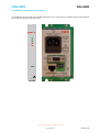
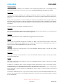
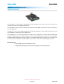
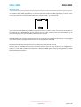
FRU-4001
PSU-4001 / PSU-4001S
PSU-4101 / PSU-4101S
CDM-4001
SMU-4000
3RU Eurocard Frame with SNMP Control & Power Supplies
User Manual
IRT Electronics Pty Ltd | www.irtelectronics.com
Revision 02
FRU-4001
PSU-4001 / PSU-4001S
PSU-4101 / PSU-4101S
CDM-4001
SMU-4000
3RU EUROCARD FRAME WITH SNMP CONTROL & POWER SUPPLIES
Revision History:
Revision
00
01
Date
23/04/2008
20/01/2011
By
AL
AL
02
06/06/2014
AL
Change Description
Original Issue.
Title descriptor changed to match that of DC frame’s
handbook format for consistency.
Reformatted layout.
Applicable to:
S/N: ≥ 0801001
S/N: ≥ 0801001
S/N: ≥ 0801001
IRT Electronics Pty Ltd | www.irtelectronics.com
Page 2 of 33
Revision 02
FRU-4001
PSU-4001 / PSU-4001S
PSU-4101 / PSU-4101S
CDM-4001
SMU-4000
USER MANUAL
Table of Contents:
Section
Page
Revision History
2
Operational Safety
5
FRU-4001 3 RU Eurocard Frame
General Description
Technical Specifications
Circuit Description
Installation
Power Supply Module
CDM-4001 SNMP Agent Module
Eurocard Module
EMC
Front and Rear Location Diagrams
6
6
7
8
9
9
9
10
11
12
PSU-4001/PSU-4001S AC Power Supply
General Description
Technical Specifications
Circuit Description
Pre-Installation
Earthing
Installation
Performance
FRU-4001 Frame
Front & Rear Panel Connector Diagrams
13
13
14
15
15
15
16
16
16
17
PSU-4101/PSU-4101S -48V DC Power Supply
General Description
Technical Specifications
Circuit Description
Pre-Installation
Earthing
Installation
Performance
FRU-4001 Frame
Internal Adjustments
Front & Rear Panel Connector Diagrams
18
18
19
20
20
20
21
21
21
21
22
CDM-4001 SNMP Agent Frame Controller
General Description
Technical Specifications
Installation
Front & Rear Panel Connector Diagrams
Setup
23
23
24
25
26
27
SMU-4000 SNMP Plug-in Management Controller
General Description
Installation
29
29
30
IRT Electronics Pty Ltd | www.irtelectronics.com
Page 3 of 33
Revision 02
FRU-4001
PSU-4001 / PSU-4001S
PSU-4101 / PSU-4101S
CDM-4001
SMU-4000
Table of Contents (continued):
Section
Page
SNMP – What Is It?
31
Maintenance & Storage
33
Warranty & Service
33
This instruction book applies to units later than S/N: 0801001.
IRT Electronics Pty Ltd | www.irtelectronics.com
Page 4 of 33
Revision 02
FRU-4001
PSU-4001 / PSU-4001S
PSU-4101 / PSU-4101S
CDM-4001
SMU-4000
OPERATIONAL SAFETY
WARNING
Operation of electronic equipment involves the use of voltages and currents that
may be dangerous to human life. Note that under certain conditions dangerous
potentials may exist in some circuits when power controls are in the OFF position.
Maintenance personnel should observe all safety regulations.
Do not make any adjustments inside equipment with power ON unless proper
precautions are observed. All internal adjustments should only be made by suitably
qualified personnel. All operational adjustments are available externally without
the need for removing covers or use of extender cards.
WARNING
AC Power Supplies
Whilst every effort has been made to prevent exposure of service personnel to
dangerous voltages, AC mains input power supplies are by their nature dangerous
when connected to the AC mains supply.
Wherever possible maintenance work on power supplies should be carried out with
the mains input disconnected - NOT just switched off.
When testing units with the mains supply ON, the supply should be connected
through an earth leakage circuit breaker and should not be done without another
person in attendance.
IRT Electronics Pty Ltd | www.irtelectronics.com
Page 5 of 33
Revision 02
FRU-4001
3RU Eurocard Frame
GENERAL DESCRIPTION
The grouping of products with a common frame and mains power supply benefits the user by providing economy
and maximum utilisation of valuable space.
Different modules, including digital and analogue, may be mixed in the one frame to provide a compact solution to
system design and ease of later expansion.
Provision is made for two power supplies (AC or DC) for redundancy, although the frame can be used with only a
single supply.
With two supplies fitted, the FRU-4001 will take up to 10 IRT current series Eurocards. If only a single power supply
is fitted, the maximum number of Eurocards increases to 12 by removing the second power supply rear assembly.
When fitted with a CDM-4001 SNMP Agent module the FRU-4001 frame has the added capability of Simple
Network Management Protocol (SNMP) monitoring and control. The CDM-4001 has its own designated slot and
does not affect the number of modules that can be loaded into the frame.
SNMP allows remote monitoring and control of modules via an Ethernet connection by a computer using third
party Network Management Software. Modules must be fitted with their own relevant Management Information
Base (MIB) sub modules.
The FRU-4001 frame will take all IRT 4000 series Eurocards as well as current 700 and 3000 series Eurocards that
have the correct type of power connector on the rear assembly.
Standard features:
•
•
•
Provision for two power supplies for redundancy.
Holds up to 10 IRT Eurocard modules with two supplies fitted, or 12 IRT Eurocard modules
with a single supply fitted.
Simple Network Management Protocol (SNMP) capability.
IRT Electronics Pty Ltd | www.irtelectronics.com
Page 6 of 33
Revision 02
FRU-4001
TECHNICAL SPECIFICATIONS
3 RU SNMP Frame plus Power Supply
FRU-4001 frame
Power Supply
Input Voltage
Frequency
Fusing
Output
Redundancy
†
Alarm outputs
Standards
approvals
Power input
SNMP**:
Ethernet
Connector
RS232
Other:
Temperature
Mechanical
Dimensions
Frame finish
PSU finish
PSU-4001
240 Vac ± 10%
220 Vac ± 10%
130 Vac ± 10%
110 Vac ± 10%
45 Hz - 65 Hz
500 mA anti-surge*
14-0-14 Vac
80 VA max.
Yes (when 2 x PSUs used in frame)
Terminal block
AS3260
Selectable:
PSU-4101
-48Vdc ± 25%
(48Vdc Positive Ground)
DC
1.5 A anti-surge
±16 Vdc
+16V @ 1.6A, -16V @ 1.6A
Yes (when 2 x PSUs used in frame)
Terminal block
N140
N140
IEC 320 (per PSU)
Terminal Block
10/100 baseT
RJ45
9 pin female 'D' connector
0 - 50° C ambient
3 RU 19" rack frame
482 x 132 x 253 mm
Passivated mild steel and anodised aluminium
Front panel - APO grey, black lettering & red IRT logo,
Body & rear panel - bright finish passivated steel with silk screened black lettering.
* Use 1 A anti-surge fuse for 110 Vac (or 130 Vac) operation.
**For SNMP operation, FRU-4001 must be fitted with CDM-4001 SNMP Agent module.
† Alarm outputs only active when fitted with CDM-4001 SNMP Agent module.
Note: Network Management System (NMS) software is third party software.
A basic NMS is available free of charge on the IRT Electronics website.
Due to our policy of continuing development, these specifications are subject to change without notice.
IRT Electronics Pty Ltd | www.irtelectronics.com
Page 7 of 33
Revision 02
FRU-4001
CIRCUIT DESCRIPTION
The FRU-4001 frame can distribute to each module two low voltage centre tapped power supplies. One supply is
fitted into slots 13 and 14 (hereby designated as main supply, or PSU-A), the second power supply (herby
designated as secondary supply, or PSU-B) fitted into slots 11 and 12. The use of two supplies gives complete
power supply redundancy. When a frame is fitted with two supplies any one supply can be temporarily removed
without causing interruptions.
Normally the supplies would be PSU-4001 AC supplies but can optionally be PSU-4101 DC supplies. When PSU-4001
AC power supplies are used, the two supplies distributed are both 28Vac, centre tapped. When two PSU-4101 DC
power supplies are used, the two supplies are both + and – 16Vdc. All IRT modules will operate with either of these
supplies.
Failure of each supply is reported to the optional CDM-4001 SNMP agent module. This module, in addition to
raising an SNMP trap, will indicate the failure by switching a relay to ground. This contact is available on the centre
pin (labeled Alarm) of a three-pin connector of the main supply rear assembly (PSU-A) on the rear of the frame.
The alarm condition will only occur with a CDM-4001 card fitted to the frame and either the failure of one of the
supplies or the power feed to the supply. Physically removing a supply from the frame will not cause an alarm
condition to occur.
In order for the rear alarm connector to operate without a CDM-4001 card fitted, an optional alarm board,
FRA-4001, can be fitted in the designated slot that is normally reserved for the CDM-4001 card. Without either the
CDM-4001 card or FRA-4001 card fitted the rear alarm connector will not operate.
IRT Electronics Pty Ltd | www.irtelectronics.com
Page 8 of 33
Revision 02
FRU-4001
INSTALLATION
Power Supply Module
The frame will operate with either one or two power supply modules installed.
The power supply modules slide in from the front of the frame via guides in the Eurocard slot positions 13/14 or
11/12 at the right hand end of the frame. The four retaining screws on the front should be tightened.
Connect power input to rear of frame. For DC input, observe the polarity markings next to each connector.
Due to its weight if the frame is to be freighted for any purpose the power supply should be removed and packed
separately before shipment.
If only 1 power supply is to be fitted and the frame to be used for 12 Eurocard modules, remove the 2nd power
supply rear assembly (PSU-B) allowing Eurocard slot positions 11 & 12 to become available.
CDM-4001 SNMP Agent Module
If the FRU-4001 frame is to be fitted with SNMP capability, then the CDM-4001 SNMP Agent module needs to be
installed.
Looking at the front view of the FRU-4001 frame, remove the main power supply from slot positions 13/14. The
main power supply front panel covers over the CDM-4001 slot position (slot 15) at the very right end of the frame.
In order to fit the CDM-4001 SNMP agent module the main power supply front panel needs to be replaced with the
narrower front panel (supplied together with the CDM-4001 module) by removing the 4 mounting screws off the
front panel of the power supply. Swap over the handle from the original supply front panel to the narrower panel
and then attaching the narrower panel to the supply by the same 4 mounting screws.
Slide the CDM-4001 module into the slot 15 guides all the way until the module mates with the 96-pin connector at
the rear of the frame, and then tighten the two front retaining screws. Once the CDM-4001 card has been
installed, re-install the main power supply fitted with the narrower front panel.
Signal connections to this card are via the rear of the frame below the IEC mains plug input. The 9 pin female D9
connector is an RS-232 interface for connection to a computer for initial setup parameters of the frame for SNMP
use. The RJ45 connector is for Ethernet connection.
IRT Electronics Pty Ltd | www.irtelectronics.com
Page 9 of 33
Revision 02
FRU-4001
Eurocard Module
In order for an IRT Eurocard to be mounted within the FRU-4001 frame, the rear assembly must be fitted with
power pins to pick up power from the frame power bus. All IRT 4000 series cards come fitted with these pins and
are fully compatible with the FRU-4001 frame as are current 700 and 3000 series Eurocard modules that have the
correct type of power connector on the rear assembly. Older versions of 700 and 3000 series Eurocard modules
that do not have the power pins on the rear assembly are not compatible with the FRU-4001 frame.
Ensure that the rear assembly has the correct orientation and carefully align the power pins and SNMP pins over
power and SNMP bus connectors. With equal pressure to the top and bottom of the rear assembly, press until the
rear assembly PCB touches the frame mounting rails at the top and bottom. Install the two retaining screws
(Metric M2.5 x 10 mm).
SNMP Bus
SNMP
Bus Pins
Eurocard
Rear Assembly
Power
Pins
Power Bus
Rear assemblies may be removed for maintenance. Make sure that extraction force is applied equally and steadily
at the top and bottom of the rear assembly simultaneously.
If extraction force is not equally applied, there is a good
chance that the module connector pins will be bent,
making it very difficult to re-install the rear assembly.
Slide the Eurocard module into the front of the frame in the guides corresponding to the position of the installed
mating rear assembly until it makes mating contact with the rear assembly 64 pin connector, then tighten the two
front retaining screws.
Warning
Optical Connections
The optical connectors on modules may be attached to the main module PCB, NOT the
rear connector assembly.
When installing the optical fibre sufficient slack should be allowed for the module to be
withdrawn with the optical fibre attached until the connector is clear of the frame and
can be disconnected.
If this is not done, the module will not be able to be removed without first
disconnecting the optical fibre at the rear. Attempting to remove the module without
first disconnecting the fibre may result in damage to the fibre and / or the module.
IRT Electronics Pty Ltd | www.irtelectronics.com
Page 10 of 33
Revision 02
FRU-4001
EMC
Due to EMC (electromagnetic compliance) standards, IRT recommends that all unused card positions be closed off
using IRT front blanking panels, on the front, and rear blanking panels, on the rear, of the frame.
IRT Electronics Pty Ltd | www.irtelectronics.com
Page 11 of 33
Revision 02
FRU-4001
Front & Rear Location Diagrams
The following front panel and rear assembly drawings are not to scale and are intended to show connection order
and approximate layout only.
436 mm
255 mm
285 mm
240 mm
132 mm
482 mm
FRU-4001 with one PSU fitted - Front View
P S U- 4 0 0 1
Module Positions
1
2
3
4
5
6
7
8
9
10
11
12
PSU A
AC
VOLTAGE SELECTABLE
AC POWER SUPPLY
N140
FRU-4001 with 2nd PSU and CDM-4001 “SNMP Agent” card fitted - Front View
PS U - 4 00 1 S
P S U- 4 0 0 1
CDM-4001
LNK
ACT
Module Positions
1
2
3
4
5
6
7
URG
NURG
8
9
10
PSU B
PSU A
DC
AC
AC
VOLTAGE SELECTABLE
AC POWER SUPPLY
VOLTAGE SELECTABLE
AC POWER SUPPLY
N140
N140
N140
FRU-4001 (Standard) - Rear View
110/240 V 50/60 Hz
0.7 A (max.)
110/240 V 50/60 Hz
0.7 A (max.)
FRU-4001
FRAME
FRU-4001
FRAME
PSU-B
PSU-A
AC
FUSES
AC
FUSES
220/240 Vac
500 mA S.B.
220/240 Vac
500 mA S.B.
110/120 Vac
1A S.B.
110/120 Vac
1A S.B.
Module Rear Assembly Positions
IR
9
8
7
6
5
4
3
2
1
A
Alarm
+
48Vdc
AS3260 approval no.: CS6346N
Ass. no.: 805115
+
48Vdc
A
AS3260 approval no.: CS6346N
Ass. no.: 805116
IRT Electronics Pty Ltd | www.irtelectronics.com
Page 12 of 33
Revision 02
PSU-4001/PSU-4001S
FRU-4001
AC Power Supply
GENERAL DESCRIPTION
The PSU-4001/PSU-4001S is designed to provide the low voltage AC power required for operation of up to 12
standard IRT Eurocard modules fitted within an IRT FRU-4001 frame. The PSU-4001/PSU-4001S adds the facility of
providing for selection of the AC mains input voltage by way of a selector switch on the side of the PSU.
Two PSU-4001’s/PSU-4001S’s can be operated redundantly when using an IRT FRU-4001 frame. The redundant
power supply facility of the PSU-4001/PSU-4001S is enabled in each IRT Eurocard module by having the power
supply circuit of each module made up of two bridge rectifier circuits with the outputs connected in parallel. This
allows the 28 Vac CT voltages to be sourced from either PSU-4001/PSU-4001S.
A front panel LED indicator provides visual confirmation of the presence of the low voltage output.
An alarm relay is also included which will activate the alarm in the SNMP controller module, if fitted, if either side
of the AC output fails.
A voltage selector switch allows the PSU-4001/PSU-4001S to be configured for 240V, 220V, 130V or 110V
operation.
IRT Electronics Pty Ltd | www.irtelectronics.com
Page 13 of 33
Revision 02
PSU-4001/PSU-4001S
FRU-4001
TECHNICAL SPECIFICATIONS
Power Requirements:
240 Vac ± 10%
220 Vac ± 10%
130 Vac ± 10%
110 Vac ± 10%
45 - 65 Hz ±10%
500 mA anti-surge for 240V and 220V operation,
1000 mA anti-surge for 130V and 110V operation.
Fuses are installed in the associated rear assembly.
Voltage
Frequency
Fusing
Standards Approval:
AS3260 approval no.: CS6346N
Output:
28 Vac centre tapped (14 - 0 - 14) fully loaded.
80 VA maximum.
Connectors:
AC power input / AC output
H15MFAV32 male, Faston
Other:
Temperature range
0 - 50° C ambient
Mechanical
Suitable for mounting in FRU-4001 rack frame
Finish:
Dimensions
Front panel
Body
Grey background, black lettering & red IRT logo
Passivated steel with silk-screened black lettering.
6 HP x 3 U x 230 mm
Due to our policy of continuing development, these specifications are subject to change without notice.
IRT Electronics Pty Ltd | www.irtelectronics.com
Page 14 of 33
Revision 02
PSU-4001/PSU-4001S
FRU-4001
CIRCUIT DESCRIPTION
The PSU-4001/PSU-4001S consists of a power transformer, which provides a 28 Vac centre tapped output.
All connections to the module are made via a single multi-pin connector. Extreme care should be taken when
working in the vicinity of this connector as it carries the live mains input voltage.
The front panel LED power indicator is supplied from the output with the full 28 Vac via a rectifier diode and series
resistor.
The alarm is powered from the output rails, in parallel with the LED indicator. The use of the alarm requires an
SNMP controller card within the FRU-4001 frame.
When operating normally the alarm is open circuit. When a supply is lost the alarm line is grounded.
PRE-INSTALLATION
Handling:
This equipment may be connected to static sensitive devices and proper static free handling precautions should be
observed when disconnecting or reconnecting either the input or the output of the PSU.
Power:
Set the Voltage selector switch for the correct input Mains voltage. Ensure that the correct fuses are installed in
the associated rear assembly – 1000 mA anti-surge for 130 and 110V and 500 mA anti-surge for 220 and 240V
operation.
Earthing:
Supply earth:
For safety reasons a connection is made between the IEC connector earth pin and the IRT FRU-4001 chassis. No
attempt should be made to break this earth connection.
When the PSU-4001/PSU-4001S is installed in the IRT FRU-4001 frame a connection will be made between the
above earth and the PSU-4001/PSU-4001S chassis.
Power supply output earth:
No connection is made between the centre tap of the PSU-4001/PSU-4001S low voltage output and the chassis
frame.
Signal earth:
FRU-4001 frame:
The signal earth of all IRT modules is connected to the chassis frame.
IRT Electronics Pty Ltd | www.irtelectronics.com
Page 15 of 33
Revision 02
PSU-4001/PSU-4001S
FRU-4001
INSTALLATION
The PSU-4001/PSU-4001S contains no user serviceable parts inside and should not be
opened.
In the event of failure of the supply, the input operating voltage and IEC input
connector fuse should be checked.
If fault persists the complete unit should be returned to IRT or your local agent for
service.
Performance:
One PSU-4001/PSU-4001S is designed to provide adequate power for an FRU-4001 frame equipped with its
maximum of twelve Eurocard modules under normal conditions. During normal operation, this power is shared
between two supplies mounted in the frame with a maximum of ten Eurocard modules.
This performance is contingent on two power supplies being operational and the AC mains supply input being
within the specified range.
Where both an AC and DC supply are fitted in the one frame, the degree of load sharing will be dependent on the
AC input voltage to the PSU-4001/PSU-4001S. This will directly affect its output voltage whereas the DC supply will
continue to supply a constant voltage output over a wide range of input voltages.
If only one supply is operational or the AC supply voltage to one supply is low, module performance may be
affected.
The provision of two power supplies is intended to provide continued operation, during failure of one supply, until
the second supply can be restored.
If the AC mains supply input is subject to wide fluctuation, a suitable stabilised source should be installed.
FRU-4001 Frame:
The PSU-4001/PSU-4001S should be slid firmly into either of the two double width slots (11/12 & 13/14) at the
right of the frame. The four retaining screws on the front should then be tightened. A narrow filler panel is fitted
by two retaining screws to the right of the PSU-4001S power supply except when a CDM-4001 is fitted next to the
power supply.
Power to the PSU-4001/PSU-4001S is supplied from a connector located on the rear of the FRU-4001, immediately
to the rear of the module.
Note that the IEC320 connectors have inbuilt fuses. A spare fuse may also be stored inside the connector. The fuse
should 1000 mA anti-surge for 130 and 110V operation and 500 mA anti-surge for 240 and 220V operation.
The alarm output connector is located on the rear of the FRU-4001 frame and is common to both supply units
when installed. The alarms for both units are in parallel such that when a fault develops in either PSU the alarm
output will be grounded.
Due to its weight the PSU-4001/PSU-4001S can be damaged itself or cause damage to the frame if subjected to a
large mechanical shock.
If the frame is to be freighted for any purpose, remove the
PSU-4001/PSU-4001S and pack separately before shipment taking care to
ensure that protruding edges of front fascia panel are well protected.
For this purpose we recommend the use of plastic bubble packaging.
IRT Electronics Pty Ltd | www.irtelectronics.com
Page 16 of 33
Revision 02
PSU-4001/PSU-4001S
FRU-4001
Front & Rear Panel Connector Diagrams
The following front panel and rear assembly drawings are not to scale and are intended to show relative positions
of connectors, indicators and controls only.
PSU-4001
AC
P SU - 4 0 0 1 S
AC
VOLTAGE SELECTABLE
AC POWER SUPPLY
VOLTAGE SELECTABLE
AC POWER SUPPLY
N140
Full width front panel.
N140
Narrow width front panel.
Requires filler panel (supplied).
Rear View.
IRT Electronics Pty Ltd | www.irtelectronics.com
Page 17 of 33
Revision 02
PSU-4101/PSU-4101S
FRU-4001
-48V DC Power Supply
GENERAL DESCRIPTION
The PSU-4101/PSU-4101S is designed to provide complementary low voltage DC power supplies required for
operation of up to 10 standard IRT Eurocard modules.
The IRT PSU-4101/PSU-4101S DC-DC converter converts a nominal 48V input voltage to two output supplies, one of
+16V and the other -16V with respect to ground.
Two PSU-4101's/PSU-4101S’s can be operated redundantly when using an FRU-4001 Frame. The redundant power
supply facility of the PSU-4101/PSU-4101S is enabled in each IRT Eurocard module by having the power supply
circuit of each module made up of two full wave rectifier circuits with the outputs connected in parallel. This allows
the ±16V voltages to be sourced from either PSU-4101/PSU-4101S.
A front panel LED indicator provides visual confirmation of the presence of the low voltage output.
An alarm relay is also included which will activate the alarm if either +ve or -ve output fails. The use of the alarm
requires an SNMP controller card within the FRU-4001 frame.
The PSU-4101/PSU-4101S is available in -48 Vdc only and is not configurable by the user.
IRT Electronics Pty Ltd | www.irtelectronics.com
Page 18 of 33
Revision 02
PSU-4101/PSU-4101S
FRU-4001
TECHNICAL SPECIFICATIONS
Power Requirements:
Voltage
Power
Fusing
48 Vdc ± 25% Positive ground.
1.5 A maximum.
1.5 A anti-surge
Output voltages:
+16V @ 1.6A
-16V @ 1.6A
Connectors:
DC power input / output
H15MFAV32 male, Faston
Other:
Temperature range
0 - 50° C ambient
Mechanical
Suitable for mounting in FRU-4001 rack frame
Finish:
Dimensions
Front panel
Body
Grey background, black lettering & red IRT logo
Passivated steel with silk-screened black lettering.
6 HP x 3 U x 230 mm
Due to our policy of continuing development, these specifications are subject to change without notice.
IRT Electronics Pty Ltd | www.irtelectronics.com
Page 19 of 33
Revision 02
PSU-4101/PSU-4101S
FRU-4001
CIRCUIT DESCRIPTION
The PSU-4101/PSU-4101S consists of two DC-DC converter circuits, each of which provides a 16 Vdc output. The
inputs are wired in parallel and the outputs differ only in the grounding of the positive or negative output of the
converter.
The DC input circuitry consists of a safety fuse followed by a low value series resistance and overvoltage protection
zener diode and a number of RF suppression components.
The front panel LED power indicator and alarm relay are powered from the output rails by way of a series 15 Volt
zener diode. If either rail fails there is insufficient voltage to operate the relay and the LED dims sufficiently to
indicate the fault condition.
When operating normally the alarm is open circuit. When supply is lost the alarm line is grounded. The use of the
alarm requires an SNMP controller card within the FRU-4001 frame.
PRE-INSTALLATION
Handling:
This equipment may be connected to static sensitive devices and proper static free handling precautions should be
observed when disconnecting or reconnecting either the input or the output of the PSU.
Power:
Ensure that operating voltage of unit and local DC supply voltage match, and that the polarity is correctly wired.
Earthing:
Supply earth:
For safety reasons, a connection is made between the IEC connector earth pin, the DC input connector +ve pin and
the FRU-4001. No attempt should be made to break this earth connection.
When the PSU-4101/PSU-4101S is installed in the FRU-4001 frame a connection will be made between the above
earth and the PSU-4101/PSU-4101S chassis. This earth is also connected to the centre tap output connection of the
PSU-4101/PSU-4101S.
Power supply output earth:
A connection is made between the output common connection of the PSU-4101/PSU-4101S and chassis ground
within the PSU-4101/PSU-4101S.
Signal earth:
FRU-4001:
When the rear assembly of a module is connected to the FRU-4001 frame, the signal earth of that rear assembly
may or may not be connected to the chassis depending on the particular rear assembly design.
Power supply connections on the rear assembly are not connected to the signal earth on the rear assembly.
When a module is inserted into the FRU-4001 frame, a connection is made between the PSU-4101/PSU-4101S
power supply ground and signal earth. Depending on the particular module design, the signal earth may be
connected to the front panel of the module and may therefore make a connection to the FRU-4001 frame via the
front securing screws.
This results in a central earth point on each module for power supply and signal.
General:
If a "technical" earth is required for the system, this may be connected to the rack, frame and signal earth
according to the requirements of each individual installation. For connection to the signal earth refer to details of
connections for particular modules installed in the frame.
IRT Electronics Pty Ltd | www.irtelectronics.com
Page 20 of 33
Revision 02
PSU-4101/PSU-4101S
FRU-4001
INSTALLATION
The PSU-4101/PSU-4101S contains no user serviceable parts inside and should not be
opened.
In the event of failure of either output, the input operating voltage and front panel
input fuse should be checked.
If fault persists the complete unit should be returned to IRT or your local agent for
service.
Performance:
One PSU-4101/PSU-4101S is designed to provide adequate power for an FRU-4001 frame equipped with its
maximum of ten Eurocard modules under normal conditions. During normal operation, this power is shared
between the two supplies mounted in the frame.
This performance is contingent on two power supplies being operational and the AC mains supply input being
within the specified range.
Where both an AC and DC supply are fitted in the one frame, the degree of load sharing will be dependent on the
AC input voltage to the AC supply. This will directly affect its output voltage whereas the DC supply will continue to
supply a constant voltage output over a wide range of input voltages.
Where two PSU-4101's/PSU-4101S’s are fitted in the one frame, the degree of load sharing will be dependent on
the match in output voltages between the two supplies.
If only one supply is operational or the AC supply voltage to one supply is low, module performance may be
affected.
The provision of two power supplies is intended to provide continued operation, during failure of one supply, until
the second supply can be restored. Continuous single supply operation is not recommended.
FRU-4001 Frame:
The PSU-4101/PSU-4101S should be slid firmly into either of the two double width slots (11 & 12) at the right of
the frame. The four retaining screws on the front should then be tightened. A narrow filler panel is fitted by two
retaining screws to the right of the PSU-4101S power supply except when a CDM-4001 is fitted next to the power
supply.
Power to the PSU-4101/PSU-4101S is supplied from a connector located on the rear of the FRU-4001, immediately
to the rear of the module. Care should be taken to observe the correct polarity as marked when connecting DC to
this connector.
The alarm output connector is located on the rear of the FRU-4001 frame and is common to both supply units
when installed. The alarms for both units are in parallel such that when a fault develops in either PSU the alarm
output will be grounded. The use of the alarm requires an SNMP controller card within the FRU-4001 frame.
WARNING - Each PSU-4101/PSU-4101S dissipates up to 6 Watts and a full frame of ten VA-700’s and two
PSU-4101’s/PSU-4101S’s dissipates up to 66 Watts. Ensure that adequate ventilation is available to keep down the
operating temperature. If possible, at least 44.5 mm (1 RU) should be left clear above each frame.
Internal adjustments:
The PSU-4101/PSU-4101S is factory set for the correct output voltages and should not require re-adjustment
unless one of the DC - DC converters is replaced.
Adjust RV 1 for -16 Vdc
Adjust RV 2 for +16 Vdc
IRT Electronics Pty Ltd | www.irtelectronics.com
Page 21 of 33
Revision 02
PSU-4101/PSU-4101S
FRU-4001
Front & Rear Panel Connector Diagrams
The following front panel and rear assembly drawings are not to scale and are intended to show relative positions
of connectors, indicators and controls only.
PS U- 41 01
DC
PS U-41 01S
DC
-48V
DC POWER SUPPLY
-48V
DC POWER SUPPLY
N140
Full width front panel.
N140
Narrow width front panel.
Requires filler panel (supplied).
Rear View.
IRT Electronics Pty Ltd | www.irtelectronics.com
Page 22 of 33
Revision 02
CDM-4001
FRU-4001
SNMP Agent Frame Controller
GENERAL DESCRIPTION
The CDM-4001 is a Simple Network Management Protocol (SNMP) Agent for use in IRT’s FRU-4001 3RU frame. It
occupies its own designated slot within the frame, next to the power supply, so it does not affect the number of
modules that can be used within the frame.
The CDM-4001 can communicate with all modules in a Frame that are fitted with an SMU-4000 SNMP Interface
sub-board, or have inbuilt SNMP facilities. The information obtained is forwarded via an Ethernet connection to
any SNMP Network Management System (NMS) whose address is configured in the CDM-4001.
The CDM-4001 holds parameters such as Frame Name, Address and Location. This information may be set via an
RS232 Configuration port.
The NMS third party software (not supplied by IRT) polls the CDM-4001 to remotely monitor and control the frame
and its SNMP capable modules.
In the event of a major alarm from any of the modules or power supply an alarm condition, known as a Trap, is
automatically sent without any prompting from the NMS.
Front panel LEDs indicate the presence of an Ethernet link, link activity and the Frame urgent & non-urgent alarm
states.
Ethernet connection is via an RJ45 connector and the RS232 is via a D9 female connector on the rear of the frame.
Modules that are being monitored and controlled share a common data bus on the frame.
SNMP monitoring and control finds particular use in remote or unmanned locations such as transmitter sites, or
where control via a computer is desired.
As the CDM-4001 can be assigned its own IP Address, multiple sites can be monitored and controlled via the one
NMS. Alternatively, multiple NMS’s in different locations can be used to monitor and control the same site.
Features:
• SNMP remote monitoring and control via Ethernet connection
• Automatic “Trap” transmission on major alarms
• Front panel LED indicators
• Own designated slot in the FRU-4001 3RU frame
IRT Electronics Pty Ltd | www.irtelectronics.com
Page 23 of 33
Revision 02
CDM-4001
FRU-4001
TECHNICAL SPECIFICATIONS
Ethernet:
Rate
Connector
100 baseT / 10 baseT.
RJ45 (on rear of FRU-4001 frame).
RS232:
Rate
Connector
9600 baud.
Female D9 (on rear of FRU-4001 frame).
SNMP:
Version
Configurable Settings
1.
sysContact;
sysName;
sysLocation;
Agent IP Address;
NMS IP address (max. 5);
Gateway IP address;
Subnet mask;
Community;
Agent port number;
Trap port number.
Front Panel Indicators:
LINK
ACT
URG
NURG
DC
(Green)
(Green)
(Red)
(Red)
(Green)
Ethernet present.
Activity, Communication.
Urgent Alarm detected.
Non urgent Alarm detected.
Power present.
Power requirement:
28 Vac CT (14-0-14) or ±16 Vdc.
< 5VA.
Voltage
Consumption
Other:
Temperature
Mechanical
Finish
Dimensions
Front panel
Rear assembly
0 - 50°C ambient.
Suitable for mounting in IRT 19" rack chassis with input, output and power connections
on the rear panel.
Grey background, black lettering & red IRT logo.
Part of FRU-4001 3RU frame.
3 HP x 3 U x 220 mm IRT Eurocard.
Due to our policy of continuing development, these specifications are subject to change without notice.
IRT Electronics Pty Ltd | www.irtelectronics.com
Page 24 of 33
Revision 02
CDM-4001
FRU-4001
INSTALLATION
If the FRU-4001 frame is to be fitted with SNMP capability, then the CDM-4001 SNMP Agent module needs to be
installed.
The CDM-4001 occupies its own designated spot to the very right of the FRU-4001 frame. Remove the power
supply from the frame and slide the CDM-4001 into position.
The PSU-4001 and PSU-4101 power supplies comes equipped with a 60mm width front panel that normally covers
the CDM-4001 slot. With the CDM-4001 in place it is necessary to use either the PSU-4001S or PSU-4101S power
supply that sits directly next to the CDM-4001 card with the narrower width front panel.
Signal connections to this card are via the rear of the frame below the IEC mains plug input. The 9 pin female D9
connector is an RS-232 interface for connection to a computer for initial setup parameters of the frame for SNMP
use. The RJ45 connector is for Ethernet connection.
IRT Electronics Pty Ltd | www.irtelectronics.com
Page 25 of 33
Revision 02
CDM-4001
FRU-4001
Front & Rear Panel Connector Diagrams
The following front panel and rear assembly drawings are not to scale and are intended to show relative positions
of connectors, indicators and controls only.
IRT Electronics Pty Ltd | www.irtelectronics.com
Page 26 of 33
Revision 02
CDM-4001
FRU-4001
SETUP
The communication between the CDM-4001 and the NMSs use Ethernet at either 10 or 100Mb/s.
The SNMP protocol used is Version 1. Read and Write functions use the same Community string.
To obtain a response from a CDM-4001 the Internet Protocol (IP) Destination address must be the preconfigured
Local IP Address, the IP Source Address must be one of the pre-configured NMS addresses, the UDP Port number
must match the preconfigured Agent Port, and the Community string must match the pre-configured Community
string.
The Community string is also used to address individual modules. The frame slots are numbered from 1 to 9 then A
to C (case sensitive) (giving 12 in all). To address a module the first character of the Community string must be the
module Slot number in ASCII. The second character must be “@”. The remaining characters must match the preconfigured Community string. For example suppose the Community was set as “public” then the module in Slot 1
would respond to “1@public” The CDM-4001 can also be addressed as being in slot ‘0’ (i.e. “0@public” or
“public”).
To configure the CDM-4001 connect an ASCII serial RS-232 terminal (such as Tera Term PRO) to the Configuration
port. The data rate should be 9600 baud and the byte should 8 bits data, no parity 1 stop. Upon sending ‘Enter’
you would typically see the following:
1.Local MAC address 12:34:56:78:9A:DF
2.Local IP address 192.168.0.100
3.NMS 1 IP Address 192.168.0.11 00:A0:CC:54:12:84
4.NMS 2 IP Address 255.255.255.255
5.NMS 3 IP Address 192.168.0.10 00:A0:CC:54:12:8E
6.NMS 4 IP Address 192.168.0.24 00:A0:CC:54:12:86
7.NMS 5 IP Address 192.168.0.9
00:09:5B:04:16:48
8.Gateway IP Address 192.168.0.1 00:09:5B:12:33:15
9. Subnet Mask
0.0.0.0
A.Community
public
B.Agent Port
161
C.Trap Port
162
D.sysContact
John Doe
E.sysLocation
Hotham Pde
F.sysName
north side
To change a parameter, type in the line number that you wish to change. As soon as the line number has been
typed you are able to enter the new parameter data. Pressing the ‘Enter’ key will give you a message asking if you
wish to replace the existing data with the new data. Press ‘Enter’ again to accept the change. Anything else typed
will default back to the existing parameter.
Local MAC address
This is a unique address of this particular CDM-4001 and should only be changed with great care.
Local IP address
This is the static IP address assigned to the Frame by you or your ISP.
NMS 1 IP Address
This is the IP address of one of the NMSs to which the CDM-4001 will respond. Up to 5 addresses can be used. If
any one of the addresses is not required then the address 255.255.255.255 should be entered.
Once communication has been established with a particular address then the MAC address used to communicate
with that IP address will be displayed after the IP address. If the IP address is not within the local subnet as defined
by the Gateway address and the Subnet Mask then instead of the MAC address the label “via Gateway” will
appear.
IRT Electronics Pty Ltd | www.irtelectronics.com
Page 27 of 33
Revision 02
CDM-4001
FRU-4001
Gateway IP Address
When using subnets a Gateway is the IP address of the computer appointed to pass on all messages that are
addressed to computers that are not part of your subnet. The Gateway IP address must be in your subnet.
Subnet Mask
A subnet mask is used to determine if an IP address is within your subnet or not. If the IP address is within your
subnet then you send messages directly to that IP address. If it is not then you send messages to the Gateway for it
to pass on.
Say the mask was 255.255.0.0 – and the destination IP address was 192.168.0.54 and the Gateway address was
192.168.0.1. Using binary logic you AND the IP address and the mask which results in 192.168.0.0 . Now AND the
mask and the Gateway address and you get 192.168.0.0 . These two addresses match so the destination is in your
local subnet.
If you do not want to use Gateways set the Mask to 0.0.0.0
Community
This is the Community string, which must be exactly matched for a response to be obtained. It is case sensitive and
you may use non-printable characters. The maximum length is 63.
Agent Port
This is the Agents UDP Port number. SNMP Protocol suggests that this should be 161.
Trap Port
When a Trap (an unsolicited message from a module to a NMS) is sent the Trap Port number is used as the
destination port. SNMP Protocol suggests that this should be 162. Note that when a module generates a trap, it is
sent to all of the configured NMS addresses using this Port number.
sysContact
This string is sent when a ‘Get sysContact’ is sent to the CDM-4001. Maximum length is 63 and only printable
characters should be used.
sysLocation
This string is sent when a ‘Get sysLocation’ is sent to the CDM-4001. Maximum length is 63 and only printable
characters should be used.
sysName
This string is sent when a ‘Get sysName’ is sent to the CDM-4001. Maximum length is 63 and only printable
characters should be used.
IRT-MIB.my is an SNMP MIB, which contains the Object Identifier (OID) definitions of all IRT controllable modules.
It also contains a small number of OIDs used by modules that do not have their own MIB.
IRT4000FRU-MIB.my is an SNMP MIB specifically for the CDM/FRU-4001, as well as for the earlier CDM/FRU-4000
frame combination. A ‘Walk’ command to a CDM-4001 will show (in part) a list by slot number of the type of
module installed.
If enabled, the CDM-4001 will issue a Trap on failure of either of the two possible PSU-4001/PSU-4001S PSUs in the
frame, as well as issuing Traps on each individual slot position. Trap alarms can be individually enabled or disabled
for each slot position.
IRT Electronics Pty Ltd | www.irtelectronics.com
Page 28 of 33
Revision 02
SMU-4000
FRU-4001
SNMP Plug-in Management Controller
GENERAL DESCRIPTION
The SMU-4000 is a Simple Network Management Protocol (SNMP) plug-in interface option for IRT 4000 series
modules when used in IRT’s SNMP capable frames.
The SMU-4000 is programmed with a Management Information Base (MIB) suitable for the type of module that it
is to be plugged into.
IRT 4000 series cards that are SNMP upgradeable need the SMU-4000 plug-in module programmed with their own
relevant MIB to be recognisable by the SNMP system.
The SMU-4000 acts as an interface between the module that it is plugged into and the CDM-xxxx SNMP Agent
within the SNMP capable frame. Module conditions such as alarm states or signal conditions are communicated to
the SNMP Network Management System (NMS) via the CDM-xxxx SNMP Agent. Likewise control commands are
communicated from the NMS, to the SNMP Agent, to the relevant module via the SMU-4000 plug-in module.
Standard Features:
•
•
Plug-in SNMP option for IRT 4000 series cards
Programmable Management Information Base (MIB) to suit intended module
IRT Electronics Pty Ltd | www.irtelectronics.com
Page 29 of 33
Revision 02
SMU-4000
FRU-4001
INSTALLATION
The SMU-4000 plug-in SNMP management controller module can only be fitted to IRT’s 4000 series modules that
are capable of being SNMP upgradeable. To determine whether a module is SNMP upgradeable, a square section
on the main PCB is silk screened and fitted with three multipin sockets – as shown below:
1J1
1J3
1J2
This is where the SMU-4000 plug-in SNMP management controller module is fitted. The three sets of multipins on
the underside of the SMU-4000 line up with the three sets of multipin sockets on the main PCB module. Align all
pins and then gently press the SMU-4000 all the way down into place.
If the SMU-4000 is not already programmed with the correct firmware to match the module that it is being plugged
into, it then needs to be programmed via the pins on the topside of the SMU-4000.
Note that installation will generally be done by IRT Electronics at the time of ordering.
Note also that an SMU-4000 will only be functionally operational when the main module that it is plugged into is
fitted into an IRT SNMP capable frame fitted with a CDM-xxxx SNMP agent and being interrogated by a suitable
Network Management System.
IRT Electronics Pty Ltd | www.irtelectronics.com
Page 30 of 33
Revision 02
FRU-4001
SNMP
What Is It?
SNMP stands for Simple Network Management Protocol. It is an application layer protocol for managing IP
(Internet Protocol) based systems. SNMP enables system administrators to manage system performance, and to
find and solve system problems. SNMP runs over UDP (User Datagram Protocol), which in turn runs over IP.
Three types of SNMP exist: SNMP version 1 (SNMPv1), SNMP version 2 (SNMPv2) and SNMP version 3 (SNMPv3). It
is not the intention here to discuss the differences between various versions, only to bring attention to the fact
that IRT Electronics modules, fitted with SNMP capability, use SNMPv1.
An SNMP managed network consists of three key components: Network Management Systems (NMS), agents, and
managed devices.
An NMS is the console through which the network administrator performs network management functions, such
as monitoring status (e.g. alarm states) and remote controlling, of a set of managed devices. One or more NMS’s
must exist on any managed network. Generally the NMS is a computer running third party SNMP control software.
There are a number of third party SNMP software applications currently available on the market.
An NMS polls, or communicates with, an agent. An agent is a network management software module that resides
in a managed device. An agent has local knowledge of management information and translates that information
into a form compatible with SNMP. The agent, therefore, acts as an interface between the NMS and the managed
devices. The NMS sends a request message, and control commands for the managed devices, to the agent, which
in turn sends a response message, containing information about the managed devices, back to the NMS.
A managed device contains an SNMP agent and resides on a managed network. Managed devices collect and store
management information and make this information available to NMS’s using SNMP.
Managed device agent variables are organised in a tree structure known as a Management Information Base
(MIB). Within the MIB are parameters pertaining to the managed device. An Object Identifier (OID) number within
the MIB defines the managed device type. This is a unique number specific to the model of managed device. Other
information relating to the device is also stored, information such as alarm states, controllable settings, etc. The
MIB tree is organised in such a way that there will be no two MIB files with conflicting placements.
Normally an NMS polls an agent for information relating to the MIB in a managed device to be sent back to the
NMS. When certain conditions are met within the MIB, such as major alarm conditions, for example, the agent
automatically sends what is known as a trap to the NMS without any prompting from the NMS. This allows
automatic notification of a predetermined event.
SNMP Block Diagram
NMS
IP
Network
NMS
SNMP Agent
Protocol Engine
MIB
SNMP Agent
SNMP Agent
Protocol Engine
MIB
SNMP Agent
SNMP Agent
Protocol Engine
MIB
SNMP Agent
IRT Electronics Pty Ltd | www.irtelectronics.com
Page 31 of 33
Revision 02
FRU-4001
SNMP with IRT Products:
IRT Electronics currently employs SNMPv1 with its SNMP capable frames. The frame acts as an agent when fitted
with a CDM-xxxx module. This module has its own designated slot next to the power supply so as to not affect the
number of modules that the frame will take. Communication between the NMS, the frame and its loaded modules
are via this CDM-xxxx module. Note that the NMS software is third party and not supplied by IRT Electronics.
Ethernet connection for SNMP operation is via an RJ45 connector on the rear of the frame, below the mains inlet.
Ethernet rate runs at either 10 baseT or 100 baseT.
Frame parameters, such as Name, Address and Location, are set via an RS232 interface, a D9 connector on the rear
of the frame below the mains inlet. A software terminal emulator, such as Tera Term or HyperTerminal, is used for
setting and reading the parameters of the frame.
IRT modules that are SNMP compatible need a plug-in SMU-4000 module with a program relevant to the module
that it is plugged into. Depending on the module, besides the module identification, parameters such as alarm
states, inputs and controls etc. are communicated to the CDM-xxxx agent via a data bus on the rear of the frame.
Thus the CDM-xxxx collects information on what is loaded within the frame, what positions they occupy, and their
current status for communication to the NMS when the NMS sends a request for information.
In the event of a major alarm from any of the SNMP compatible modules, or power supplies, a trap is automatically
sent by the CDM-xxxx agent to the NMS without any prompting by the NMS. This alerts the operator to any fault
conditions that may exist that need immediate attention.
110/240 V 50/60 Hz
0.7 A (max.)
FRU-4000
FRAME
FUSES
220/240 Vac
500 mA S.B.
110/120 Vac
1A S.B.
RS232
Alarm
Ethernet
+
48Vdc
AS3260 approval no.: CS6346N
Ass. no.: 804692
IRT SNMP Connections
NMS
Ethernet Cable
IP
Network
IRT modules fitted
with SMU-4000
CDM-xxxx
PSU’s
IRT SNMP Frame
Ethernet Cable
IRT modules fitted
with SMU-4000
CDM-xxxx
PSU’s
IRT SNMP Frame
Ethernet Cable
IRT SNMP Setup
IRT Electronics Pty Ltd | www.irtelectronics.com
Page 32 of 33
Revision 02
FRU-4001
MAINTENANCE & STORAGE
Maintenance:
No regular maintenance is required.
Care however should be taken to ensure that all connectors are kept clean and free from contamination of any
kind. This is especially important in fibre optic equipment where cleanliness of optical connections is critical to
performance.
Storage:
If the equipment is not to be used for an extended period, it is recommended the whole unit be placed in a sealed
plastic bag to prevent dust contamination. In areas of high humidity a suitably sized bag of silica gel should be
included to deter corrosion.
Where individual circuit cards are stored, they should be placed in antistatic bags. Proper antistatic procedures
should be followed when inserting or removing cards from these bags.
WARRANTY & SERVICE
Equipment is covered by a limited warranty period of three years from date of first delivery unless contrary
conditions apply under a particular contract of supply. For situations when “No Fault Found” for repairs, a
minimum charge of 1 hour’s labour, at IRT’s current labour charge rate, will apply, whether the equipment is
within the warranty period or not.
Equipment warranty is limited to faults attributable to defects in original design or manufacture. Warranty on
components shall be extended by IRT only to the extent obtainable from the component supplier.
Equipment return:
Before arranging service, ensure that the fault is in the unit to be serviced and not in associated equipment. If
possible, confirm this by substitution.
Before returning equipment contact should be made with IRT or your local agent to determine whether the
equipment can be serviced in the field or should be returned for repair.
The equipment should be properly packed for return observing antistatic procedures.
The following information should accompany the unit to be returned:
1.
2.
3.
4.
5.
6.
7.
A fault report should be included indicating the nature of the fault
The operating conditions under which the fault initially occurred.
Any additional information, which may be of assistance in fault location and remedy.
A contact name and telephone and fax numbers.
Details of payment method for items not covered by warranty.
Full return address.
For situations when “No Fault Found” for repairs, a minimum charge of 1 hour’s labour will apply,
whether the equipment is within the warranty period or not. Contact IRT for current hourly rate.
Please note that all freight charges are the responsibility of the customer.
The equipment should be returned to the agent who originally supplied the equipment or, where this is not
possible, to IRT directly. Details of IRT’s direct address can be found at IRT Electronics’ website.
Web address: www.irtelectronics.com
Email: [email protected]
IRT Electronics Pty Ltd | www.irtelectronics.com
Page 33 of 33
Revision 02