1
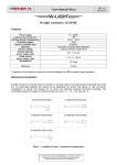
I R T Electronics Pty Ltd A.B.N. 35 000 832 575
26 Hotham Parade, ARTARMON N.S.W. 2064 AUSTRALIA
National: Phone: (02) 9439 3744
Fax: (02) 9439 7439
International:
+61 2 9439 3744
+61 2 9439 7439
Email: [email protected]
Web: www.irtelectronics.com
IRT Eurocard
Type MDC-4570
ASI to ASI
Network Interface Adapter
Designed and manufactured in Australia
IRT can be found on the Internet at:
http://www.irtelectronics.com
4570-mdc.ib.rev0.doc
Page 1 of 14
21/01/2009
IRT Eurocard
Type MDC-4570
ASI to ASI
Network Interface Adapter
Instruction Book
Table of Contents
Section
Page
Operational Safety
General Description
Technical Specifications
Technical Description
Configuration
Installation
Front and rear layouts
Operation
Front Panel Indicators
Processing controls
SNMP Functions
SNMP – What Is It?
Maintenance & Storage
Warranty & Service
Equipment return
2
3
4
5
6
7
8
9
9
10
11
12
14
14
14
This instruction book applies to units later than S/N 0901001.
Operational Safety:
WARNING
Operation of electronic equipment involves the use of voltages and currents that
may be dangerous to human life. Note that under certain conditions dangerous
potentials may exist in some circuits when power controls are in the OFF position.
Maintenance personnel should observe all safety regulations.
Do not make any adjustments inside equipment with power ON unless proper
precautions are observed. All internal adjustments should only be made by suitably
qualified personnel. All operational adjustments are available externally without the
need for removing covers or use of extender cards.
4570-mdc.ib.rev0.doc
Page 2 of 14
21/01/2009
IRT Eurocard
Type MDC-4570
ASI to ASI
Network Interface Adapter
General Description
MDC-4570
Alarms & Indications
188 BYTE BLOCK
204 BYTE BLOCK
SCRAMBLED
RS PRESENT
INPUT LOSS
SYNC ERRORS
Input
(270 Mb/s) coax
ASI-C
Convolutional
De-Interleaver
Reed-Solomon
Correction
De-Scrambling
+ RS Encode
Convolutional
Interleaver
Reed-Solomon
Insert
Scrambling
10B
8B
Outputs
(270 Mb/s) coax
ASI-C
RS ERROR
8B
10B
ASI-C
The MDC-4570 is an ASI to ASI data transcoder for converting between the commonly used MPEG2 Transport
Stream formats in the broadcast industry for video distribution.
The MDC-4570 can operate at ASI rates from 2 Mb/s to the full 213 Mb/s rate. When set up for encoding, it can
perform 188 to 204 byte conversion, scrambling, RS encoding and interleaving. When set up for decoding, it can
perform de-interleaving, RS correction, descrambling and 204 to 188 byte conversion. All functionality is switch
selectable.
The MDC-4570 finds particular use in protecting ASI streams when interfacing through various types of links, such
as microwaves, satellite, or Telco G.703 links.
SNMP (Simple Network Management Protocol) is available for monitoring of switch settings and signal parameters
when used in an IRT frame fitted with SNMP capability.
The MDC-4570 is designed to fit IRT’s standard Eurocard frames and may be used alongside any other of IRT’s
analogue or digital Eurocards.
Standard features:
•
ASI to ASI conversion.
•
Reed Solomon encoding & decoding.
•
Interleaving or de-interleaving.
•
Scrambling or de-scrambling.
•
Packet length indication.
•
188 to 204 & 204 to 188 byte conversion, where appropriate.
•
SNMP capable.
4570-mdc.ib.rev0.doc
Page 3 of 14
21/01/2009
Technical Specifications
IRT Eurocard module
Type/s MDC-4570
Input :
Type
ASI Rate
1 x ASI, 75Ω BNC connector, or
2 Mb/s to 213 Mb/s
Outputs :
Type
2 x ASI-C 75Ω, 800 mVp-p, BNC connector.
Alarms:
Major
Minor
Relay goes open circuit on loss of Sync, or power loss.
Relay goes open circuit when an uncorrectable error occurs,
(or a correctable error if switch SW4-5 is ON), or power loss.
Power Requirements:
28 Vac CT (14-0-14) or ± 16 Vdc.
2.5 VA.
Power consumption
Connectors:
Other:
Temperature range
0 - 50° C ambient
Mechanical
Finish:
Front escutcheon
Rear assembly
Grey background, black lettering & red IRT logo
Detachable silk-screened PCB with direct mount connectors to
Eurocard and external signals
Dimensions
6 HP x 3 U x 220 mm IRT Eurocard
Standard accessories
Rear connector assembly including matching connector for
alarm output.
Due to our policy of continuing development, these specifications are subject to change without notice.
4570-mdc.ib.rev0.doc
Page 4 of 14
21/01/2009
Technical Description
The MDC-4570 processes an ASI input and outputs two processed ASI-C at the input data rate.
This module is capable of performing scrambling, de-scrambling, RS encoding, RS decoding, interleaving and deinterleaving. It can encode as well as decode different MPEG TS formats. The module is normally set up as either a
decoder or an encoder. Certain combinations of functions are inhibited (e.g. de-interleaving of a 188 byte transport
stream with or without 188/204 conversion enabled).
The processing functions are selected using three switches (interleaving, RS coding and scrambling) on the front
panel. Each switch has three positions (up, centre or down).
A switch set to the UP position applies processing to the decoding section.
A switch set to the DOWN position applies processing to the encoding section.
A switch set to the CENTRE position bypasses the decoding and encoding sections.
Applying a function to both the decoder and encoder section simultaneously is prevented mechanically by the
switch.
Applying an encoding function on one switch with a decoding function on another switch is an invalid operation.
Non-sensible output may result in this situation.
ASI Output
ASI operates at 270 Mbit/s and uses 8B/10B coding with K28.5 stuffing bytes. Two ASI cable outputs each use a
75 Ohm BNC connector.
Alarm relays
Major Alarm (“Loss of ASI sync”) and Minor Alarm (“Uncorrectable Error” or “Correctable Error with switch
SW4-5 ON”) relay contacts are available on PL8 of the rear assembly. Relays go open circuit on alarm condition.
Both Major and Minor alarms switch to open circuit on power failure.
LED indicators
LED indicators 188 TS Byte length, 204 TS Byte length, RS error, SCRAM present, RS present are blanked during
Input loss or sync loss.
4570-mdc.ib.rev0.doc
Page 5 of 14
21/01/2009
Configuration
Switch settings:
The only user settings on the MDC-4570 is on the DIP switch SW4 as shown below:
SW4-1 ON SW4-1 OFF -
188 to 204 byte conversion enabled
188 to 204 byte conversion disabled
SW4-2 ON SW4-2 OFF -
204 to 188 byte conversion enabled
204 to 188 byte conversion disabled
SW4-3
-
Factory use only.
SW4-4 ON
-
SW4-4 OFF -
TEI* bit (Transport Error Indicator) set in outgoing stream if an uncorrectible error is
detected.
TEI* bit (Transport Error Indicator) in outgoing stream is unchanged.
SW4-5 ON SW4-5 OFF -
R-S led shows both correctible and uncorrectible errors
R-S led shows uncorrectible errors only.
SW4-6 ON SW4-6 OFF -
not used
not used
SW4-7
Factory use only
-
SW4-8 ON SW4-8 OFF -
Output SNMP alarms non-operational (for use with older FRU-4000 frame).
Output SNMP alarms operational
Note that for a 188 byte input signal, SW4-1 must be ON for full encoding functionality (Reed Solomon,
Interleaving).
CAUTION: Do not have both switches SW4-1 and SW4-2 ON at the same time.
* TEI – b7 of byte after sync byte.
If set, indicates current packet contains uncorrectable RS errors.
This bit is set by the MDC-4570 if SW4-4 is ON, the RS decoder is operating, and the current packet
has uncorrectible RS errors.
4570-mdc.ib.rev0.doc
Page 6 of 14
21/01/2009
Installation
Pre-installation:
Handling:
This equipment may contain or be connected to static sensitive devices and proper static free handling precautions
should be observed.
Where individual circuit cards are stored, they should be placed in antistatic bags. Proper antistatic procedures
should be followed when inserting or removing cards from these bags.
Power:
AC mains supply:
Ensure that operating voltage of unit and local supply voltage match and that correct rating
fuse is installed for local supply.
DC supply:
Ensure that the correct polarity is observed and that DC supply voltage is maintained within
the operating range specified.
Earthing:
The earth path is dependent on the type of frame selected. In every case particular care should be taken to ensure
that the frame is connected to earth for safety reasons. See frame manual for details.
Signal earth: For safety reasons a connection is made between signal earth and chassis earth. No attempt should be
made to break this connection.
Installation in frame or chassis:
See details in separate manual for selected frame type.
Input/Output & alarm connections:
ASI input and ASI outputs are by 75Ω BNC connectors on the rear assembly.
Alarm outputs are by a 4-pin Phoenix style screw connector on the rear assembly. Alarms are by FET relay
contacts. Relays go open circuit on alarm condition. Both Major and Minor alarms switch to open circuit on power
failure.
1
GND
2
GND
3
MAJOR ALARM
4
MINOR ALARM
The Major Alarm condition is “Loss of ASI sync”.
The Minor Alarm condition is “Uncorrectable Errors” or “Correctable Errors with switch SW4-5 set to ON”.
NOTE: In order for Minor Alarm to operate, need RS decoding ON.
4570-mdc.ib.rev0.doc
Page 7 of 14
21/01/2009
Front & rear panel connector diagrams
The following front panel and rear assembly drawings are not to scale and are intended to show connection order
and approximate layout only.
MD C -4 5 7 0
1–GND
2–GND
3–MAJOR
4–MINOR
PL6
1
2
ALARM O/P
3
4
ALARM
PL8
INPUT
INPUT
188
SYNC
204
R-S
SCRAM
SK 5
IN3
SK 3
OUT3
ASI I/P
R-S
SCRAM
REED
SOLOMON
INTERLEAVE
ASI O/P (1)
SK 7
UP - DECODE
CENTRE - OFF
DOWN - ENCODE
OUT4
ASI O/P (2)
PL5
NOT USED
DC
NOT USED
SK 11
NOT USED
G.703 IN
SK 2
PL7
G.703 OUT
N140
4570-mdc.ib.rev0.doc
Page 8 of 14
21/01/2009
Operation
The MDC-4570 primarily operates in either encode or decode mode. The three front panel switches determine the
coding or decoding operations performed. Both outputs contain the same coded information. Not all combinations
of encoding and decoding are valid or optimal for use with MPEG2 transport streams. The user must be aware of
the intended application and the Transport Stream format used.
Switches in the CENTER position do not affect encoding or decoding, switches in the UP position apply to
decoding and switches in the DOWN position apply to encoding.
The application of certain processing functions is automatically blocked if the incoming stream is not in a suitable
format, e.g. if the incoming Transport Stream contains 188 Byte packets then neither Interleaving, De-Interleaving,
Reed Solomon encoding or Reed Solomon Decoding can be applied. The MDC-4570 provides a visual indication of
the incoming Transport Stream format, e.g. Packet size 188/204, Scrambling or RS coding. These indicators help
the user decide which processing functions are required.
In most encoding applications the switches would typically be in the center or down position. Whilst in most
decoding applications the switches would typically be in the center or up position. It would be unusual to use switch
combinations where one or more switches are in the up position whilst one or more switches are in the down
position.
TS Transmission Formats
The application of scrambling, interleaving and RS encoding is required prior to satellite or terrestrial modulators
(e.g. QPSK modulation for satellite). Interleaving and RS coding are almost always used together. Interleaving
reduces the impact of burst errors by redistributing the error burst over multiple packets. Since the RS decoder can
only correct up to 8 bytes per packet, this increases the likelihood of all the errors being corrected. If a packet has
more than 8 errored bytes, an RS decoder will be unable to correct that packet. Scrambling or energy dispersal on
the other hand helps maintain DC balance on the transmission line and allows equiprobable detection threshold to
be used.
Front Panel Indicators:
Input loss alarm:
This LED lights when no ASI input is detected.
Sync loss alarm:
This LED lights when there are 8B/10B errors in the input stream.
INPUT
188
SYNC
204
R-S
SCRAM
R-S
188 byte indicator:
This LED lights when a valid MPEG-2 TS with 188 byte packet length is input.
204 byte indicator:
This LED lights when a valid MPEG-2 TS with 204 byte packet length is input.
Scrambling presence indicator:
This LED lights when a valid MPEG-2 TS stream containing a byte sequence that corresponds to scrambling. A
scrambling byte sequence uses an inverted 47H sync byte (B8H) every eighth sync to signify the start of the
scrambling sequence.
R-S (Reed Solomon) presence indicator (Green):
This LED lights when Reed Solomon error correction bytes are present in place of the 16 dummy bytes of a 204
Byte MPEG-2 TS. The MDC-4570 considers any data content other than all 0’s or all FF’s during the 16 dummy
bytes to be RS correction bytes.
R-S (Reed Solomon) Error indicator (Red):
This LED lights for 2 seconds when un-correctable RS packets are detected. These correspond to packets with more
than 8 bytes in error. This LED will also light up if correctable RS packets are present and SW4-5 is set to ON.
4570-mdc.ib.rev0.doc
Page 9 of 14
21/01/2009
Processing controls:
This module is capable of performing scrambling, de-scrambling, RS encoding, RS decoding, interleaving and deinterleaving.
In this context, the word scrambling refers to the process of randomisation for the purpose of energy dispersal of the
signal. It does not refer to the encryption applied to Pay TV signals to control access to particular channels or
programs.
For a description of the processes involved see Application examples - Cable Systems and Technical specifications Characteristics of signal types - MPEG-2 transport layer coding.
The module is normally set up as either a decoder or an encoder. Combinations of both functions simultaneously
should be avoided.
The processing functions are selected using three switches (interleaving, RS coding
and scrambling) on the front panel. Each switch has three positions (up, centre or
down).
A switch set to the UP position applies processing to the decoding section;
a switch set to the DOWN position applies processing to the encoding section; and
a switch set to the CENTRE position does not perform that function to either the
decoding or encoding section.
In most instances, the MDC-4570 would be set to all encode or all decode.
4570-mdc.ib.rev0.doc
Page 10 of 14
SCRAM
REED
SOLOMON
INTER
LEAVE
UP
- DECODE
CENTRE - OFF
DOWN - ENCODE
21/01/2009
SNMP Functions:
With the MDC-4570 installed in an IRT frame with SNMP capability, the unit can be interrogated by an SNMP
Network Management System (NMS).
The following SNMP functions are capable of being monitored and controlled by an NMS:
Alarms:
The current state of the Urgent (Major) and Non Urgent (Minor) Alarms;
Switch Status:
An indication of the Scramble (SCRAM) front panel switch setting;
An indication of the REED SOLOMON front panel switch setting;
An indication of the INTERLEAVE front panel switch setting;
An indication of the 188 to 204 Byte conversion DIP switch setting (SW4-1);
An indication of the 204 to 188 Byte conversion DIP switch setting (SW4-2);
Input Status:
An indication that an input signal is present;
An indication of the input signal packet size (188 or 204 Byte);
An indication of the approximate input data rate;
An indication of if the input signal has energy dispersal scrambling added;
An indication of if the input signal has Reed Solomon bytes;
RS Error Monitoring:
Enables Reed Solomon error monitoring;
An indication of the accumulated number of correctable Reed Solomon errors*;
An indication of the accumulated number of uncorrectable Reed Solomon errors*;
An indication of the number of sync loss periods†;
Allows naming of a 15 byte maximum Alias for the input signal;
An indication of the firmware version of the main FPGA;
An indication of the software version of the main FPGA;
Unit Reset;
Trap Generation:
Allows enabling of a Trap to be sent when the input is first present or first lost;
Allows enabling of a Trap to be sent when an RS uncorrectable errored period occurs;
Allows enabling of a Trap to be sent when an RS correctable errored period occurs;
NOTE: * Error counters use.31 bit counters (213 – 1).
† A Sync Loss period is a 250ms interval. This means that a sync loss, or multiple sync losses,
has occurred in a 250ms time frame.
To reset counters, re-enable Reed Solomon error monitoring.
4570-mdc.ib.rev0.doc
Page 11 of 14
21/01/2009
SNMP
What Is It?
SNMP stands for Simple Network Management Protocol. It is an application layer protocol for managing IP
(Internet Protocol) based systems. SNMP enables system administrators to manage system performance, and to find
and solve system problems. SNMP runs over UDP (User Datagram Protocol), which in turn runs over IP.
Three types of SNMP exist: SNMP version 1 (SNMPv1), SNMP version 2 (SNMPv2) and SNMP version 3
(SNMPv3). It is not the intention here to discuss the differences between various versions, only to bring attention to
the fact that IRT Electronics modules, fitted with SNMP capability, use SNMPv1.
An SNMP managed network consists of three key components: Network Management Systems (NMS), agents, and
managed devices.
An NMS is the console through which the network administrator performs network management functions, such as
monitoring status (e.g. alarm states) and remote controlling, of a set of managed devices. One or more NMSs must
exist on any managed network. Generally the NMS is a computer running third party SNMP control software. There
are a number of third party SNMP software applications currently available on the market.
An NMS polls, or communicates with, an agent. An agent is a network management software module that resides in
a managed device. An agent has local knowledge of management information and translates that information into a
form compatible with SNMP. The agent, therefore, acts as an interface between the NMS and the managed devices.
The NMS sends a request message, and control commands for the managed devices, to the agent, which in turn
sends a response message, containing information about the managed devices, back to the NMS.
A managed device contains an SNMP agent and resides on a managed network. Managed devices collect and store
management information and make this information available to NMSs using SNMP.
Managed device agent variables are organised in a tree structure known as a Management Information Base (MIB).
Within the MIB are parameters pertaining to the managed device. An Object Identifier (OID) number within the
MIB defines the managed device type. This is a unique number specific to the model of managed device. Other
information relating to the device is also stored, information such as alarm states, controllable settings, etc. The MIB
tree is organised in such a way that there will be no two MIB files with conflicting placements.
Normally an NMS polls an agent for information relating to the MIB in a managed device to be sent back to the
NMS. When certain conditions are met within the MIB, such as major alarm conditions, for example, the agent
automatically sends what is known as a trap to the NMS without any prompting from the NMS. This allows
automatic notification of a predetermined event.
SNMP Block Diagram
NMS
IP Network
NMS
4570-mdc.ib.rev0.doc
Page 12 of 14
SNMP Agent
Protocol Engine
MIB
SNMP Agent
SNMP Agent
Protocol Engine
MIB
SNMP Agent
SNMP Agent
Protocol Engine
MIB
SNMP Agent
21/01/2009
SNMP with IRT Products:
IRT Electronics currently employs SNMPv1 with its SNMP capable frames. The frame acts as an agent when fitted
with a CDM-xxxx module. This module has its own designated slot next to the power supply so as to not affect the
number of modules that the frame will take. Communication between the NMS, the frame and its loaded modules
are via this CDM-xxxx module. Note that the NMS software is third party and not supplied by IRT Electronics.
Ethernet connection for SNMP operation is via an RJ45 connector on the rear of the frame, below the mains inlet.
Ethernet rate runs at either 10 baseT or 100 baseT.
Frame parameters, such as Name, Address and Location, are set via an RS232 interface, a D9 connector on the rear
of the frame below the mains inlet. A software terminal emulator, such as Tera Term or HyperTerminal, is used for
setting and reading the parameters of the frame.
IRT modules that are SNMP compatible need a plug-in SMU-4000 module with a program relevant to the module
that it is plugged into. Depending on the module, besides the module identification, parameters such as alarm states,
inputs and controls etc. are communicated to the CDM-xxxx agent via a data bus on the rear of the frame. Thus the
CDM-xxxx collects information on what is loaded within the frame, what positions they occupy, and their current
status for communication to the NMS when the NMS sends a request for information.
In the event of a major alarm from any of the SNMP compatible modules, or power supplies, a trap is automatically
sent by the CDM-xxxx agent to the NMS without any prompting by the NMS. This alerts the operator to any fault
conditions that may exist that need immediate attention.
110/240 V 50/60 Hz
0.7 A (max.)
FRU-4000
FRAME
FUSES
220/240 Vac
500 mA S.B.
110/120 Vac
1A S.B.
RS232
Alarm
Ethernet
+
48Vdc
AS3260 approval no.: CS6346N
Ass. no.: 804692
IRT SNMP Connections
IRT modules fitted
with SMU-4000
NMS
Network
Ethernet Cable
CDM-xxxx
PSU’s
IRT SNMP Frame
Ethernet Cable
IRT modules fitted
with SMU-4000
CDM-xxxx
PSU’s
IRT SNMP Frame
Ethernet Cable
IRT SNMP Setup
4570-mdc.ib.rev0.doc
Page 13 of 14
21/01/2009
Maintenance & Storage
Maintenance:
No regular maintenance is required.
Care however should be taken to ensure that all connectors are kept clean and free from contamination of any kind.
This is especially important in fibre optic equipment where cleanliness of optical connections is critical to
performance.
Storage:
If the equipment is not to be used for an extended period, it is recommended the whole unit be placed in a sealed
plastic bag to prevent dust contamination. In areas of high humidity a suitably sized bag of silica gel should be
included to deter corrosion.
Where individual circuit cards are stored, they should be placed in antistatic bags. Proper antistatic procedures
should be followed when inserting or removing cards from these bags.
Warranty & Service
Equipment is covered by a limited warranty period of three years from date of first delivery unless contrary
conditions apply under a particular contract of supply. For situations when “No Fault Found” for repairs, a
minimum charge of 1 hour’s labour, at IRT’s current labour charge rate, will apply, whether the equipment is within
the warranty period or not.
Equipment warranty is limited to faults attributable to defects in original design or manufacture. Warranty on
components shall be extended by IRT only to the extent obtainable from the component supplier.
Equipment return:
Before arranging service, ensure that the fault is in the unit to be serviced and not in associated equipment. If
possible, confirm this by substitution.
Before returning equipment contact should be made with IRT or your local agent to determine whether the
equipment can be serviced in the field or should be returned for repair.
The equipment should be properly packed for return observing antistatic procedures.
The following information should accompany the unit to be returned:
1.
2.
3.
4.
5.
6.
7.
A fault report should be included indicating the nature of the fault
The operating conditions under which the fault initially occurred.
Any additional information, which may be of assistance in fault location and remedy.
A contact name and telephone and fax numbers.
Details of payment method for items not covered by warranty.
Full return address.
For situations when “No Fault Found” for repairs, a minimum charge of 1 hour’s labour will apply,
whether the equipment is within the warranty period or not. Contact IRT for current hourly rate.
Please note that all freight charges are the responsibility of the customer.
The equipment should be returned to the agent who originally supplied the equipment or, where this is not
possible, to IRT direct as follows.
Equipment Service
IRT Electronics Pty Ltd
26 Hotham Parade
ARTARMON
N.S.W.
2064
AUSTRALIA
Phone:
Email:
4570-mdc.ib.rev0.doc
61 2 9439 3744
[email protected]
Page 14 of 14
Fax:
61 2 9439 7439
21/01/2009