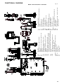
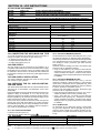
1
Verve
High efficiency system boiler
Users Instructions
Installation &
Servicing
Instructions
THESE INSTRUCTIONS
TO BE RETAINED
BY USER
Vokèra is a licensed member of the Benchmark scheme
which aims to improve the standards of installation and
commissioning of domestic hot water systems in the UK.
Users instructions
Things you should know
1.1
Gas appliances
1.2
Electrical supply
1.3
Guarantee registration card
1.4
Appliance Log Book (UK only)
1.5
How does it work?
1.6
Dimensions
1.7
Clearances required
1.8
Frost protection system
1.9
Appliance status indicators
Page
1
1
1
1
1
1
1
1
1
Getting started
2.1
Before switching ON
2.2
Appliance controls
2.3
Lighting the boiler
2.4
Adjusting the heating temperature
2.5
Explanation of features
2.6
Automatic temperature control
Page
3
3
3
3
3
3
How
3.1
3.2
3.3
3.4
3.5
to...
How
How
How
How
How
Page
3
3
3
3
3
What
4.1
4.2
4.3
4.4
if...
What if I suspect a gas leak
What if I have frequently top-up the system
What if the appliance is due its annual service
What if I need to call an engineer
to top-up the system pressure
to reset the appliance
to shut down the system for short periods
to shut down the system for long periods
to care for the appliance
Page
4
4
4
4
Installation and Servicing instructions
Design principles & operating sequence
1.1
Principle components
1.2
Mode of operation (at rest)
1.3
Mode of operation (heating)
1.4
Safety devices
Page
6
6
6
6
Technical data
2.1
Central heating
2.2
Gas pressures
2.3
Dimensions
2.4
Clearances
2.5
Connections
2.6
Electrical
2.7
Flue details (concentric 60-100)
2.8
Flue details (concentric 80-125)
2.9
Flue details (twin pipes)
2.10 Efficiency
2.11 Emissions
2.12 Pump duty
Page
7
7
7
7
7
7
7
7
7
7
7
8
General requirements (UK)
3.1
Related documents
3.2
Location of appliance
3.3
Gas supply
3.4
Flue system
3.5
Air supply
3.6
Water circulation
3.7
Electrical supply
3.8
Mounting on a combustible surface
3.9
Timber framed buildings
3.10 Inhibitors
3.11 Showers
Page
9
9
9
9
9
9
10
10
10
10
10
General requirements (EIRE)
3A.1 Related documents
3A.2 Location of appliance
3A.3 Gas supply
3A.4 Flue system
3A.5 Air supply
3A.6 Water circulation
3A.7 Electrical supply
3A.8 Mounting on a combustible surface
3A.9 Timber framed buildings
3A.10 Inhibitors
3A.11 Showers
3A.12 Declaration of conformity
Page
10
10
10
10
11
11
11
11
11
11
11
11
Installation
4.1
Delivery
4.2
Contents
4.3
Unpacking
4.4
Preparation for mounting the appliance
4.5
Fitting the flue
4.6
Connecting the gas & water
4.7
Electrical connections
Page
12
12
12
12
12
15
16
Commissioning
5.1
Gas supply installation
5.2
The heating system
5.3
Initial filling of the system
5.4
Initial flushing of the system
5.5
Pre-operation checks
5.6
Initial lighting
5.7
Checking gas pressure & combustion analysis
5.8
Final flushing of the heating system
5.9
Setting the boiler operating temperature
5.10 Setting the system design pressure
5.11 Regulating the central heating system
5.12 Final checks
5.13 Instructing the user
Page
19
19
19
19
19
19
19
19
19
19
20
20
20
Servicing
6.1
General
6.2
Routine annual servicing
6.3
Replacement of components
6.4
Component removal procedure
6.5
Pump assembly
6.6
Safety valve
6.7
Lower automatic air release valves
6.8
Water pressure switch
6.9
Flow thermistor
6.10 Return thermistor
6.11 Printed circuit board
6.12 Gas valve
6.13 Electrodes
6.14 Flue fan
6.15 Mixer
6.16 Burner
6.17 Main heat exchanger
6.20 Condense trap removal
6.21 Flue collector removal
Page
21
21
21
21
21
21
21
21
22
22
22
22
22
23
23
23
23
24
24
Checks, adjustments and fault finding
7.1
Checking appliance operation
7.2
Appliance modes of operation
7.3
Setting the thermoregulation
7.4
Checking/adjusting the appliance fan speed
7.5
Checking the CO2 & adjusting the valve
7.6
Range rated
7.7
Combustion analysis test
7.8
External faults
7.9
Electrical checks
7.10 Component values & characteristics
7.11 Appliance status led and fault codes
7.12 Boiler configuration
Page
25
25
26
27
27
28
29
30
30
30
31
31
Wiring diagrams
8.1
External wiring
8.2
Typical control applications
8.3
Other devices
Page
26
26
26
L.P.G. instructions
10.1 Related documents
10.2 Technical data
10.3 Converting the appliance gas type
10.4 Gas supply
10.5 Gas supply installation
10.6 Checking the CO2 and adjusting the gas valve
10.7 Adjusting the appliance fan speeds
Page
33
33
33
33
33
33
34
Benchmark
36-37
RANGE RATED
This boiler can be adapted to the plant’s thermal needs.
In fact, the maximum flow rate can be set for the boiler
operating in heating mode. See the “Settings” chapter
for how to set it.
Once the required (maximum heating) power is set
indicate the value on the self-adhesive label provided.
For subsequent checks and adjustments, see the value
set.
USERS INSTRUCTIONS
INTRODUCTION
Dear Customer
Your Vokèra Verve boiler has been designed to meet and exceed the very latest standards in gas central heating technology,
and if cared for, will give years of reliable use and efficiency.
Please therefore take some time to read these instructions carefully.
Do’s and Don’t’s
- Do ensure that the system pressure is periodically checked
- Do ensure that the boiler should not be used by children or unassisted disabled people
- Do ensure that you know how to isolate the appliance in an emergency
- Do ensure that you are familiar with the appliance controls
- Do ensure that your installer has completed the appliance log book section
- Do not attempt to remove the appliance casing or gain internal access
- Do not hang clothes etc. over the appliance
- Do not forget to have the appliance serviced annually.
This booklet is an integral part of the appliance. It is therefore necessary to ensure that the booklet is handed to the person
responsible for the property in which the appliance is located/installed. A replacement copy can be obtained from Vokèra
customer services.
1.THINGS YOU SHOULD KNOW
1.1 GAS APPLIANCES
Gas Safety (Installations and Use) Regulations (UK).
In the interests of your safety and that of others it is a legal
requirement that all gas appliances are installed and correctly
maintained by a competent person and in accordance with the
latest regulations.
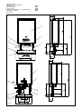
1.6 DIMENSIONS
Verve
HEIGHT
WIDTH
DEPTH
858 mm (*)
553mm
284 mm
1.2 ELECTRICAL SUPPLY
(*) with hydraulic cover
Please ensure that this appliance has been properly connected to the electrical supply by means of a double pole
isolator or un-switched socket, and that the correct size of fuse
(3 AMP) has been fitted.
Warning: this appliance must be earthed!
1.7 CLEARANCES REQUIRED
1.3 GUARANTEE REGISTRATION CARD
Please take the time to fill out your guarantee registration card.
The completed warranty card should be posted within 30 days
of installation.
1.4 APPLIANCE LOG BOOK (UK only)
A logbook section can be found at the rear of the appliance
installation booklet. This important document must be completed
during the installation/commissioning of your boiler. All GAS
SAFE registered installers carry a GAS SAFE ID card, and have
a registration number. These details should be recorded in the
Benchmark logbook section within the installation booklet. You
can check your installers details by calling GAS SAFE direct on
08004085500. Failure to install and commission the appliance
in accordance with the manufacturers instructions may
invalidate the warranty. This does not affect your statutory
rights.
1.5 HOW DOES IT WORK?
Your Verve boiler supplies heated water to your radiators and
hot water to your hot water tank.
The central heating is controlled via a time clock and any
thermostats that your installer may have fitted.
The boiler will light when it receives a request from the time
clock via any thermostat that may be installed.
Your Verve boiler lights electronically and does not have a pilot
light.
In the unlikely event of a fault developing with your boiler, the
supply of gas to the burner will be terminated automatically.
For the installation it is recommended to use an hydraulic
separator to supply the heating (fig. 20); in case of hot water use
a three way valve to supply the tank (fig. 20)
ABOVE
BELOW
LEFT SIDE
RIGHT SIDE
FRONT
see section 4
see section 4
100 mm
100 mm
600 mm
1.8 FROST PROTECTION SYSTEM
The Verve is equipped with a built-in frost protection system,
this enables the boiler to over-ride the time controls – even if
switched off – and operate the burner and/or pump, should the
temperature drop below 50C for the main. In particular the
burner will be in ON status until the main temperature reaches
35°C for CH appliance.
Please note that the frost protection system is designed to
protect the appliance only, should frost protection be required
for the heating system, additional controls may be required.
NOTE
The frost protection system is reliant on the appliance having
a permanent electrical supply, and being in a non-fault
condition.
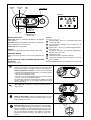
1.9 APPLIANCE STATUS INDICATORS
Your boiler is equipped with 3 status LED indicators, the Green
LED indicates that the flame is present, the Red LED indicates
the appliance has detected a fault, whilst the Yellow LED
indicates that there is Servicing operation in progress, and
with a display that indicates the operating temperature and
the fault codes.
1
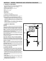
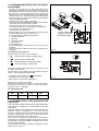
Fig. 1
GREEN
LED
YELLOW
LED
RED
LED
HYDROMETRE
DISPLAY
65
DISPLAY
MODE
SELECTOR
SWITCH
HEATING
TEMPERATURE
SELECTOR
BOILER STATUS LED
Green LED Boiler is working/responding to a heating/hot
water request
Red LED Boiler has identified a fault and has failed-safe.
Refer to instructions on how to reset
Yellow LED Service operation
DISPLAY
Description of the icons
DISPLAY
Indicates the operating temperature and the fault codes
PRESSURE GAUGE
Ensure the system pressure is set correctly (minimum 0.5bar)
MODE SELECTOR SWITCH/HEATING TEMPERATURE
SELECTOR
Mode selector switch:
65
System loading - this icon is visualised together with
a fault code A 04
Heat-adjustment: indicates the connection to an
external probe
Flame failure - this icon is visualised together with a
fault code A 01
Irregularity: indicates any operating irregularities,
together with a fault code
Heating operation
Domestic hot water operation (optional)
Anti-freeze: indicates that the anti-freeze cycle has
been activated
Heating/domestic hot water temperature or fault code
Heating & hot water - Select this position when you want the
boiler to respond to a heating request from the time-clock
programmer and hot water request from the tank thermostat
Heating temperature selector: move the selector clockwise
to increase the heating outlet temperature, or counter-clockwise
to reduce the temperature range:
- 40°C-80°C for standard systems
- 20°C-45°C for floor heating heating (contact Vokera technical
if used in conjunction with DHW cylinder)
The automatic temperature control function (SARA) is set within
position 4 and 6 (55 ÷65 °C), the display indicates the heating
water temperature
Hot water only: only used in conjunction with the optional 3
way valve kit.
Boiler at OFF/standby - Select this position when you want
the boiler to be switched off for short periods (days) or if the
boiler requires to be reset
Pressure gauge shows the current pressure of your heating
system, the gauge should be set between 1,5 and 2.0 BAR.
When the appliance is operating the gauge may rise or fall
slightly, this is quite normal. The minimum permissible level for
the safe and efficient operation of the appliance is 0.5 BAR.
Should the pressure fall below 0.5 BAR, the boiler may
lockout.
2
correct
pressure
value
2. GETTING STARTED
2.1 BEFORE SWITCHING ON
2.3 LIGHTING THE BOILER
Before switching the appliance on, please familiarise yourself with:
- how to isolate the appliance from the gas, water, and electricity supplies;
- how to check and top-up – if necessary – the system water
pressure;
- the time clock or programmer (if fitted);
- any external thermostats and their functions;
- the appliance controls.
Ensure the gas and electrical supply to the boiler are turned on.
Turn the mode selector switch to the ON position.
After being powered, the boiler begins an automatic vent cycle
lasting approximately 2 minutes.
.
During this phase the display shows the icons
To interrupt the automatic vent cycle proceed as follows:
access the electronic board by removing the casing, turning the
control panel towards you and opening the board cover.
push the SW1 (CO) button (fig. 40)
2.2 APPLIANCE CONTROLS (see fig. 1)
The appliance controls are situated on the lower front of the
appliance. The appliance controls include:
- pressure gauge;
- appliance mode selector;
- temperature selector;
- display
- burner ON mode (green);
- fault indicator (red);
- servicing mode indicator (yellow)
- optional integral time clock/programmer (if fitted).
NOTE
The appliance frost protection is active in all the boiler modes.
The temperature selector can be used to vary the temperature
of the water that circulates around your radiators.
The display and LEDS normally show the status of the appliance.
When the status indicator (Green) is lit it indicates that the
flame is present and the burner is ON.
When the fault indicator (Red) is lit it indicates that the
appliance has identified a possible fault and performed a safety
lockout.
When the fault indicator (Yellow) is lit it indicates that there is
a Servicing operation in progress.
The integral time clock (when fitted) can be used to switch the
heating on and off at pre-determined intervals.
When there is a request for heating or hot water , the boiler will
begin an ignition sequence. When the appliance reaches the
target temperature, the burner will go off for a minimum period
of approximately 3 minutes.
When the programmer/time clock or external thermostats
request has been satisfied, the appliance will switch off
automatically.
2.4 ADJUSTING THE HEATING TEMPERATURE
Rotate the temperature selector – clockwise to increase,
counter-clockwise to decrease – to the desired temperature
setting.
Depending on the type of the system, it is possible to pre-select
the suitable temperature range:
- standard systems: 40-80 °C
- floor systems: 20-45 °C
For further details consult the”Boiler configuration” section
7.12.
2.5 EXPLANATION OF FEATURES
Although the Vokèra Verve has been designed for simplicity of
use, it utilises the latest in boiler technology, enabling a host of
functions to be carried out simultaneously.
2.6 AUTOMATIC TEMPERATURE CONTROL
The automatic temperature control function (SARA), permits
the boiler (when the heating temperature selector is set within
4 and 6 sector) to automatically adjust (raise) the heating.
The activation and the disable of the function is visualized by
blinking the green led.
3. HOW TO...
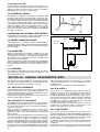
3.1 HOW TO TOP-UP THE SYSTEM PRESSURE
(fig. 1-2)
3.3 HOW TO SHUT DOWN THE SYSTEM FOR
SHORT PERIODS
The system pressure must be checked periodically to ensure
the correct operation of the boiler. The needle on the gauge
should be reading between 1.5 and 2.0 BAR when the boiler
is in an off position and has cooled to room temperature. If the
pressure requires ‘topping-up’ use the following instructions
as a guide.
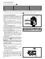
- Locate the filling valve connections (usually beneath the
boiler, see fig. 2).
- Attach the filling loop to both connections.
- Open the filling valve slowly until you hear water entering the
system.
- Close the filling valve when the pressure gauge (on the
boiler) reads between 1.5 and 2.0 BAR (see fig. 1).
- Remove the filling loop from the connections.
The system and boiler can be shut down for short periods by
simply turning the time clock to the off position. It is also
advisable to turn off the main water supply to the house.
3.2 HOW TO RESET THE APPLIANCE
When the red fault LED is illuminated, the appliance will require
to be reset manually. Before resetting the boiler, check what
action is required to be taken, using the information on the
fault code table below. Allow a period of two minutes to
elapse before rotate the mode selector knob across the
position (see fig. 1).
IMPORTANT
If the appliance requires to be reset frequently, it may be
indicative of a fault, please contact your installer or Vokèra
Customer Services for further advice.
3.4 HOW TO SHUT DOWN THE SYSTEM FOR
LONG PERIODS
If the house is to be left unoccupied for any length of time –
especially during the winter – the system should be thoroughly
drained of all water. The gas, water, and electricity supply to the
house should also be turned off. For more detailed advice
contact your installer.
3.5 HOW TO CARE FOR THE APPLIANCE
To clean the outer casing use only a clean damp cloth. Do
not use any scourers or abrasive cleaners.
Fig. 2
control
valve
temporary
connection
flow/return
pipe
double
check valve
control
valve
supply pipe
3
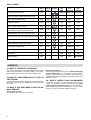
FAULT CODES
Alarm
type
Purge cycle mode active
Alarm
code
NA
Display
Led
RED
Led
YELLOW
BLINKING BLINKING
Led
GREEN
BLINKING
Ignition failure, flame not sensed, condense
sensor activated, differential pressure fault
Final
A 01
ON
OFF
OFF
Alarm high limit thermostat
Final
A 02
BLINKING
OFF
OFF
Failure fan speed
Finale
A 03
ON
OFF
ON
Alarm system water pressure
Final
A 04
ON
OFF
ON
Final
A 07
ON
OFF
OFF
Final
A 08
ON
OFF
OFF
Failure flue sensor, cleaning primary exchanger
Final
A 09
BLINKING
OFF
BLINKING
Alarm high limit flue sensor
Final
A 09
ON
OFF
OFF
Alarm underfloor heating thermostat
Final
A 77
ON
OFF
OFF
Combustion analysis test
NA
A CO
OFF
BLINKING
OFF
Service operation
NA
A DJ
OFF
BLINKING
OFF
Flame ON
NA
OFF
OFF
ON
Boiler stand-by
NA
OFF
OFF
BLINKING
Flow temperature too high, temperature
differential too high, flow thermistor fault
Return temperature too high, temperature
differential too high, return thermistor fault
4. WHAT IF...
4.1 WHAT IF I SUSPECT A GAS LEAK
If you suspect a gas leak, turn off the gas supply at the gas meter
and contact your installer or local gas supplier. If you require
further advice please contact your nearest Vokèra office.
4.2 WHAT IF I HAVE FREQUENTLY TO TOP-UP
THE SYSTEM
If the system regularly requires topping-up, it may be indicative
of a leak. Please contact your installer and ask him to inspect
the system.
4.3 WHAT IF THE APPLIANCE IS DUE ITS ANNUAL SERVICE
Advice for tenants only
Your landlord should arrange for servicing.
4
Advice for homeowners
Please contact Vokèra Customer Service (0844 3910999 (UK)
or 056 7755057 (ROI) if you would prefer a Vokèra service
engineer or agent to service your appliance. Alternatively your
local GAS SAFE registered engineer may be able to service the
appliance for you.
4.4 - WHAT IF I NEED TO CALL AN ENGINEER
If you think your boiler may have developed a fault, please
contact your installer or Vokèra Customer Services (0844
3910999 (UK) or 056 7755057 (ROI) have all your details to
hand including full address and postcode, relevant contact
numbers, and your completed appliance log book.
INSTALLATION AND SERVICING INSTRUCTIONS
INTRODUCTION
The Verve is a high-efficiency boiler with outputs of 47kW.
This appliance – by design – incorporate electronic ignition,
circulating pump, differential pressure switch, safety valve,
pressure gauge, premix combustion and radial aluminium
heat exchanger.
Verve is produced as room sealed, category II2H3P appliances,
suitable for internal wall mounting applications only. Each
appliance is provided with a fan powered flue outlet with an
annular co-axial combustion air intake that can be rotated –
horizontally – through 360 degrees for various horizontal or
vertical applications. The Verve can also be used with the
Vokèra twin flue system.
The Verve is approved for use with C13 & C33 type flue
applications.
These appliances are designed for use with a sealed system
only; consequently they are not intended for use on open
vented systems.
This booklet is an integral part of the appliance. It is therefore
necessary to ensure that the booklet is handed to the person
responsible for the property in which the appliance is located/
installed. A replacement copy can be obtained from Vokèra
customer services.
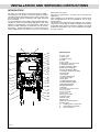
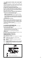
General layout
R
F
G
1 Return valve
2 Drain valve
3 Condense trap
4 Pump
5 Gas nozzle
6 Differential pressure switch
7 Condense collector
8 Return thermistor (NTC)
9 Main heat exchanger
10 Flues thermistor (NTC)
11 Flue gas analysis test point
12 Flue outlet
13 Air intake
14 Ignition transformer
15 Air suction pipe
16 Top AAV
17 High limit thermostat
18 Flow thermistor (NTC)
19 Sensing Electrode
20 Spark Electrode
21 Burner
22 Condensate level sensor
23 Air-gas mxer
24 Fan assembly
25 Gas valve
26 Pressure switch
27 Safety valve
28 Drain valve
29 Gas valve
30 Electric connection box
31 Flow valve
Heating return connection
R
Heating flow connection
F
G
Gas connection
Fig. 3
5
SECTION 1 - DESIGN PRINCIPLES AND OPERATING SEQUENCE
1.1 PRINCIPLE COMPONENTS
• A fully integrated electronic control board featuring electronic
temperature control, anti-cycle control, pump over-run, selfdiagnostic fault indicator, full air/gas modulation
• Aluminium heat exchanger
• Electronic ignition with flame supervision
• Integral high-head pump
• Fan
• Water pressure switch
• Flue sensor
• Pressure gauge
• Safety valve
• Differential pressure switch
1.2 MODE OF OPERATION (at rest)
When the appliance is at rest and there are no requests for
heating or hot water, the following functions are active:
• frost-protection system – the frost-protection system protects
the appliance against the risk of frost damage. For CH line,
if the main temperature falls to 5°C, the appliance will
function on minimum power until the temperature on main
reaches 35°C.
• anti-block function – the anti-block function enables the
pump to be energised for short periods, when the appliance
has been inactive for more than 24-hours.
1.3 MODE OF OPERATION
Flow temperature
sensor
Heating
When there is a request for heat via the time clock and/or any
external control, the pump and fan are started, the fan speed
will modulate until the correct signal voltage is received at the
control PCB. At this point an ignition sequence is enabled.
Ignition is sensed by the electronic circuit to ensure flame
stability at the burner. Once successful ignition has been
achieved the boiler’s output will either be increase to maximum
or modulate to suit the set requirement.
When the appliance reaches the desired temperature the
burner will shut down and the boiler will perform a three-minute
anti-cycle (timer delay).
When the request for heat has been satisfied the appliance
pump and fan may continue to operate to dissipate any residual
heat within the appliance.
Top AAV
Main heat
exchanger
Manual vent
valve
Return
temperature
sensor
Differential
pressure
switch
Hot water (optional 3-way valve kit installed)
When there is a request for heat via tank thermostat, the
external 3-way valve switches on tank circuit, the pump and fan
are started, the fan speed will modulate until the correct signal
voltage is received at the control PCB. At this point an ignition
sequence is enabled.
Ignition is sensed by the electronic circuit to ensure flame
stability at the burner. Once successful ignition has been
achieved the boiler’s output will either be increase to maximum
or modulate to suit 80 °C.
When the hot water reaches the desired temperature (tank
thermostat opened) the burner will shut down, the pump is off
and 3-way valve switches on heating circuit.
Pump
Pressure
switch
Safety
valve
Drain
valve
CH
return
1.4 SAFETY DEVICES
When the appliance is in use, safe operation is ensured by:
• a water pressure switch that monitors system water pressure
and will de-activate the pump, fan, and burner should the
system water pressure drop below the rated tolerance;
• fan speed sensor to ensure safe operation of the burner;
• a high limit thermostat that over-rides the temperature control
circuit to prevent or interrupt the operation of the burner;
• flame sensor that will shut down the burner when no flame
signal is detected;
• flue sensor;
• a safety valve which releases excess pressure from the
primary circuit;
• a sensor that interrupts the operation of the appliance if the
condense pipe becomes blocked
• a differential pressure switch that monitors system water flow
and will de-achtivate the gas valve.
6
Fig. 4
CH
flow
SECTION 2 - TECHNICAL DATA
2.1 Central Heating
Heat input (kW)
Maximum heat output (kW) 60/80°C
Mimum heat output (kW) 60/80°C
Maximum heat output (kW) 30/50°C
Mimum heat output (kW) 30/50°C
Minimum working pressure
Maximum working pressure
Minimum flow rate
2.2 Gas Pressures
Inlet pressure (G20)
Heating maximum gas rate (m3/hr)
Minimum gas rate (m3/hr)
Injector size (mm)
2.3 Dimensions
Height (mm)
Width (mm)
Depth (mm)
Dry weight (kg)
2.4 Clearances
Sides
Top
Bottom
Front
2.5 Connections
Flow & return
Gas
Safety valve
Condense
2.6 Electrical
Power consumption (Watts)
Supply (V/Hz)
Internal fuse
External fuse
2.7 Flue Details (concentric 60/100)
Maximum horizontal flue length (60/100mm)
Maximum vertical flue length (60/100mm)
2.8 Flue Details (concentric 80/125)
Maximum horizontal flue length (80/125mm)
Maximum vertical flue length (80/125mm)
2.9 Flue Details (twin pipes)
Maximum horizontal flue length (80mm/80mm)
Maximum vertical flue length (80mm/80mm)
2.10 Efficiency
SEDBUK (%)
2.11 Emissions
CO2 @ maximum output (%)
CO2 @ minimum output (%)
CO @ maximum output (ppm)
CO @ minimum output (ppm)
NOx maximum output (ppm)
NOx minimum output (ppm)
NOx rating
VERVE
47.00
45.78
9.00 (G20)
12.00 (G31)
49.91
9.72 (G20)
12.71(G31)
0.5 bar
3.5 bar
2000 l/h (*)
20.0 mbar
4.97
0.95
9.2
858 with hydraulic cover
553
284
39
100 mm
see section 4
see section 4
600 mm
1½” mm
22 mm
15 mm
21 mm
164W
230/50
3.15A T (for PCB) - 3.15A F (for connections block)
3A
1.8m
2.8m
4.8m
7.0m
20m/20m
20m/20m
90.08
9.0
9.5
200
20
30
25
class 5
Ref. Condition 15 °C, 1013,25 mbar, dry gas
NOTE: L.P.G. data refer to section 10
*The system should be so designed and balanced to ensure a
minimum and maximum temperature differential of 10 °C and
20 °C respectively, when the appliance is operating at maximum
output.
7
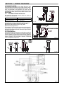
2.12 PUMP DUTY
Fig. 6 shows the flow-rate available – after allowing for pressure
loss through the appliance – for system requirements. When
using this graph, apply only the pressure loss of the system. The
graph is based on a 20oC temperature differential.
6,8
6,4
6,0
Residual head (x 100 mbar)
5,6
5,2
4,8
4,4
4,0
3,6
3,2
2,8
2,4
2,0
1,6
1,2
0,8
0,4
0,0
Fig. 5
0
100
200
300
400
500
600
700
800
900
1000
1100
1200
1300
1400
1500
1600
1700
1800
1900
2000
Flow rate (l/h)
Fig. 6
Key
8
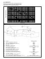
Location
A
B
C
D
E
F
G
H
I
J
K
L
M
N
P
Q
Below an opening (window, air-brick, etc.)
Above an opening (window, air-brick, etc.)
To the side of an opening (window, air-brick, etc.)
Below gutter, drain-pipe, etc.
Below eaves
Below balcony, car-port roof, etc.
To the side of a soil/drain-pipe, etc.
From internal/external corner
Above ground, roof, or balcony level
From a surface or boundary facing the terminal
From a terminal facing a terminal
From an opening in the car-port into the building
Vertically from a terminal on the same wall
Horizontally from a terminal on the same wall
From a structure to the side of the vertical terminal
From the top of the vertical terminal to the roof flashing
R
S
T
V
W
To the side of a boundary
To the side of an opening or window on a pitched roof
Below an opening or window on a pitched roof
From a vertical terminal to an adjacent opening (window, air-brick, etc.)
From a vertical terminal to an adjacent vertical terminal
Minimum distance
300 mm
300 mm
300 mm
25 mm
25 mm
25 mm
25 mm (60mm for 80/125 - 5” flue)
25 mm (60mm for 80/125 - 5” flue)
300 mm
600 mm
1200 mm
1200 mm
1500 mm
300 mm
300 mm
As determined by the fixed collar
of the vertical terminal
300 mm
600 mm
2000 mm
(call Vokera technical for advice)
300 mm (only if both terminals are the same hight)
SECTION 3 - GENERAL REQUIREMENTS (UK)
This appliance must be installed by a competent person in
accordance with the Gas Safety (Installation & Use)
Regulations.
The guard must be fitted centrally over the terminal. Refer to BS
5440 Part 1, when the terminal is 0.5 metres (or less) below
plastic guttering or 1 metre (or less) below painted eaves.
3.1 RELATED DOCUMENTS
3.5 AIR SUPPLY
The installation of this boiler must be in accordance with the
relevant requirements of the Gas Safety (Installation & Use)
Regulations, the local building regulations, the current I.E.E.
wiring regulations, the bylaws of the local water undertaking,
the Building Standards (Scotland) Regulation and Building
Standards (Northern Ireland) Regulations.
It should be in accordance also with any relevant requirements
of the local authority and the relevant recommendations of the
following British Standard Codes of Practice.
The following notes are intended for general guidance only.
This appliance is a room-sealed, fan-flued boiler, consequently
it does not require a permanent air vent for combustion air
supply. When installed in a cupboard or compartment, ventilation
for cooling purposes is also not required.
3.2 LOCATION OF APPLIANCE
The appliance may be installed in any room or internal space,
although particular attention is drawn to the requirements of the
current I.E.E. wiring regulations, and in Scotland, the electrical
provisions of the Building Regulations, with respect to the
BS
BS
BS
BS
BS
BS
BS
5440
5440
5449
5546
6798
6891
7074
PART 1
PART 2
PART 1
PART 1
3.6 WATER CIRCULATION
Detailed recommendations are given in BS 5449 Part 1 and BS
6798. The following notes are for general guidance only.
3.6.1 PIPEWORK
It is recommended that copper tubing to BS 2871 Part 1 is used
in conjunction with soldered capillary joints. Where possible
pipes should have a gradient to ensure air is carried naturally
to air release points and that water flows naturally to drain
FLUES
FLUES & VENTILATION
FORCED CIRCULATION HOT WATER SYSTEMS
INSTALLATION OF GAS HOT WATER SUPPLIES FOR DOMESTIC PURPOSES
INSTALLATION OF BOILERS OF RATED INPUT NOT EXCEEDING 60kW
LOW PRESSURE INSTALLATION PIPES
APPLICATION, SELECTION, AND INSTALLTION OF EXPANSION VESSELS
AND ANCILLARY EQUIPMENT FOR SEALED WATER SYSTEMS
installation of the appliance in a room or internal space
containing a bath or shower.
When an appliance is installed in a room or internal space
containing a bath or shower, the appliance or any control
pertaining to it must not be within reach of a person using the
bath or shower. The location chosen for the appliance must
permit the provision of a safe and satisfactory flue and
termination. The location must also permit an adequate air
supply for combustion purposes and an adequate space for
servicing and air circulation around the appliance. Where the
installation of the appliance will be in an unusual location
special procedures may be necessary, BS 6798 gives detailed
guidance on this aspect. A compartment used to enclose the
appliance must be designed and constructed specifically for
this purpose. An existing compartment/cupboard may be utilised
provided that it is modified to suit. Details of essential features
of compartment/cupboard design including airing cupboard
installations are given in BS 6798. This appliance is not
suitable for external installation.
3.3 GAS SUPPLY
The gas meter – as supplied by the gas supplier – must be
checked to ensure that it is of adequate size to deal with the
maximum rated input of all the appliances that it serves.
Installation pipes must be fitted in accordance with BS 6891.
Pipe work from the meter to the appliance must be of adequate
size. Pipes of a smaller size than the appliance gas inlet
connection must not be used. The installation must be tested
for tightness in accordance with BS6891.
If the gas supply serves more than one appliance, it must be
ensured that an adequate supply is maintained to each
appliance when they are in use at the same time.
cocks. Except where providing useful heat, pipes should be
insulated to avoid heat loss and in particular to avoid the
possibility of freezing. Particular attention should be paid to
pipes passing through ventilated areas such as under floors,
loft space and void areas.
3.6.2 HYDRAULIC SEPARATOR
Vokera advise that the appliance should be combined with a
hydraulic separator (20028475) to supply the heating system
to ensure the correct flow rate through the boiler at all times.
(see fig. 19)
3.6.3 DRAIN COCKS
These must be located in accessible positions to facilitate
draining of the appliance and all water pipes connected to the
appliance. The drain cocks must be manufactured in accordance
with BS 2879.
3.6.4 AIR RELEASE POINTS
These must be positioned at the highest points in the system
where air is likely to be trapped. They should be used to expel
trapped air and allow complete filling of the system.
3.6.5 EXPANSION VESSEL
The boiler is not fitted with an expansion tank, so you must
install a closed tank on the system to ensure the correct
appliance functions.
The dimensions of the expansion tank must be suitable for the
heating system characteristics and the tank capacity must meet
the requisites of the current regulations.
3.4 FLUE SYSTEM
3.6.6 FILLING POINT
A method for initial filling of the system and replacing water lost
during servicing etc. directly from the mains supply, is provided
(see fig. 7). This method of filling complies with the current Water
Supply (Water Fittings) Regulations 1999 and Water By laws
2000 (Scotland). If an alternative location is preferred, it should
be connected as detailed in fig. 7.
The terminal should be located where the dispersal of
combustion products is not impeded and with due regard for the
damage and discoloration that may occur to building products
located nearby. The terminal must not be located in a place
where it is likely to cause a nuisance (see fig. 7). In cold and/
or humid weather, water vapour will condense on leaving the
terminal; the effect of such pluming must be considered.
If installed less than 2m above a pavement or platform to which
people have access (including balconies or flat roofs) the
terminal must be protected by a guard of durable material.
3.6.7 LOW PRESSURE SEALED SYSTEM
An alternative method of filling the system would be from an
independent make-up vessel or tank mounted in a position at
least 1 metre above the highest point in the system and at
least 5 metres above the boiler (see fig. 8).
The cold feed from the make-up vessel or tank must be fitted
with an approved non-return valve and stopcock for isolation
purposes. The feed pipe should be connected to the return
pipe as close to the boiler as possible.
9
3.6.8 FREQUENT FILLING
Frequent filling or venting of the system may be indicative of a
leak. Care should be taken during the installation of the
appliance to ensure all aspects of the system are capable of
withstanding pressures up to at least 3.5 bar.
3.7 ELECTRICAL SUPPLY
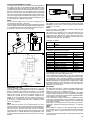
control
valve
The appliance is supplied for operation on 230V @ 50Hz
electrical supply; it must be protected with a 3-amp fuse. The
method of connection to the mains electricity supply must allow
for complete isolation from the supply. The preferred method
is by using a double-pole switch with a contact separation of at
least 3,5mm (3° high-voltage category). The switch must only
supply the appliance and its corresponding controls, i.e. time
clock, room thermostat, etc. Alternatively an un-switched
shuttered socket with a fused 3-pin plug both complying with
BS 1363 is acceptable.
flow/return
pipe
double
check valve
Fig. 7
If the appliance is to be fitted on a wall of combustible material,
a sheet of fireproof material must protect the wall.
Automatic
air-vent
Non-return
valve
3.10 INHIBITORS
Vokèra recommend that an inhibitor - suitable for use with
aluminium heat exchangers - is used to protect the boiler and
system from the effects of corrosion and/or electrolytic action.
The inhibitor must be administered in strict accordance with
the manufacturers instructions*.
*Water treatment of the complete heating system - including the
boiler - should be carried out in accordance with BS 7593 and
the Domestic Water Treatment Association’s (DWTA) code of
practice.
3.11 SHOWERS
supply
pipe
Make-up vessel
or tank
3.9 TIMBER FRAMED BUILDINGS
If the appliance is to be fitted in a timber framed building, it
should be fitted in accordance with the Institute of Gas Engineers
publication (IGE/UP/7) ‘Guide for Gas Installations in Timber
Frame Buildings’.
control
valve
Fig. 8
Stopcock
5.0 metres minimum
3.8 MOUNTING ON A COMBUSTIBLE SURFACE
temporary
connection
Heating
return
If the appliance is intended for use with a shower, the shower
must be thermostatically controlled and be suitable for use
with a combination boiler.
SECTION 3A - GENERAL REQUIREMENTS (EIRE)
This appliance must be installed by a competent person in
accordance with and defined by, the Standard Specification
(Domestic Gas Installations) Declaration (I.S. 813).
3A.1 RELATED DOCUMENTS
The installation of this boiler must be in accordance with the
relevant requirements of the local building regulations, the
current ETCI National Rules for Electrical Installations and the
bylaws of the local water undertaking.
It should be in accordance also with any relevant requirements
of the local and/or district authority.
3A.2 LOCATION OF APPLIANCE
The appliance may be installed in any room or internal space,
although particular attention is drawn to the requirements of
the current ETCI National Rules for Electrical Installations,
and I.S. 813, Annex K.
When an appliance is installed in a room or internal space
containing a bath or shower, the appliance or any control
pertaining to it must not be within reach of a person using the
bath or shower.
The location chosen for the appliance must permit the provision
of a safe and satisfactory flue and termination. The location
must also permit an adequate air supply for combustion
purposes and an adequate space for servicing and air circulation
around the appliance. Where the installation of the appliance
will be in an unusual location special procedures may be
necessary, refer to I.S. 813 for detailed guidance on this aspect.
A compartment used to enclose the appliance must be designed
10
and constructed specifically for this purpose. An existing
compartment/cupboard may be utilised provided that it is
modified to suit.
This appliance is not suitable for external installation.
3A.3 GAS SUPPLY
The gas meter – as supplied by the gas supplier – must be
checked to ensure that it is of adequate size to deal with the
maximum rated input of all the appliances that it serves.
Installation pipes must be fitted in accordance with I.S. 813.
Pipe work from the meter to the appliance must be of adequate
size. Pipes of a smaller size than the appliance gas inlet
connection must not be used. The installation must be tested
for tightness in accordance with I.S. 813.
If the gas supply serves more than one appliance, it must be
ensured that an adequate supply is maintained to each
appliance when they are in use at the same time.
3A.4 FLUE SYSTEM
The terminal should be located where the dispersal of
combustion products is not impeded and with due regard for the
damage and discoloration that may occur to building products
located nearby. The terminal must not be located in a place
where it is likely to cause a nuisance (see I.S. 813).
In cold and/or humid weather, water vapour will condense on
leaving the terminal; the effect of such pluming must be
considered.
If installed less than 2m above a pavement or platform to which
people have access (including balconies or flat roofs) the
terminal must be protected by a guard of durable material. The
guard must be fitted centrally over the terminal. Refer to I.S. 813,
when the terminal is 0.5 metres (or less) below plastic guttering
or 1 metre (or less) below painted eaves.
3A.5 AIR SUPPLY
The following notes are intended for general guidance only.
This appliance is a room-sealed, fan-flued boiler, consequently
it does not require a permanent air vent for combustion air
supply.
When installed in a cupboard or compartment, ventilation for
cooling purposes is also not required.
3A.6 WATER CIRCULATION
Specific recommendations are given in I.S. 813. The following
notes are for general guidance only.
3A.6.1 PIPEWORK
It is recommended that copper tubing be used in conjunction
with soldered capillary joints.
Where possible pipes should have a gradient to ensure air is
carried naturally to air release points and that water flows
naturally to drain cocks.
Except where providing useful heat, pipes should be insulated
to avoid heat loss and in particular to avoid the possibility of
freezing. Particular attention should be paid to pipes passing
through ventilated areas such as under floors, loft space and
void areas.
3A.6.2 HYDRAULIC SEPARATOR
Vokera advise that the appliance should be combined with a
hydraulic separator (20028475) to supply the heating system
to ensure the correct flow rate through the boiler at all times.
(see fig. 19)
3A.6.3 DRAIN COCKS
These must be located in accessible positions to facilitate
draining of the appliance and all water pipes connected to the
appliance.
3A.6.4 AIR RELEASE POINTS
These must be positioned at the highest points in the system
where air is likely to be trapped. They should be used to expel
trapped air and allow complete filling of the system.
3A.6.5 EXPANSION VESSEL
WARNING: the boiler is not fitted with an expansion tank, so
you must install a closed tank on the system to ensure the
correct appliance functions.
The dimensions of the expansion tank must be suitable for the
heating system characteristics and the tank capacity must meet
the requisites of the current regulations.
3A.7 ELECTRICAL SUPPLY
The appliance is supplied for operation on 230V @ 50Hz
electrical supply; it must be protected with a 3-amp fuse. The
method of connection to the mains electricity supply must allow
for complete isolation from the supply. The preferred method
is by using a double-pole switch with a contact separation of at
least 3,5 mm (3° high-voltage category). The switch must only
supply the appliance and its corresponding controls, i.e. time
clock, room thermostat, etc.
3A.8 MOUNTING ON A COMBUSTIBLE
SURFACE
If the appliance is to be fitted on a wall of combustible material,
a sheet of fireproof material must protect the wall.
3A.9 TIMBER FRAMED BUILDINGS
If the appliance is to be fitted in a timber framed building, it
should be fitted in accordance with I.S. 813 and local Building
Regulations.
The Institute of Gas Engineers publication (IGE/UP/7) ‘Guide
for Gas Installations in Timber Frame Buildings’ gives specific
advice on this type of installation.
3A.10 INHIBITORS
Vokèra recommend that an inhibitor - suitable for use with
aluminium heat exchangers - is used to protect the boiler and
system from the effects of corrosion and/or electrolytic action.
The inhibitor must be administered in strict accordance with
the manufacturers instructions*.
*Water treatment of the complete heating system - including the
boiler - should be carried out in accordance with I.S. 813 and
the Domestic Water Treatment Association’s (DWTA) code of
practice.
3A.11 SHOWERS
If the appliance is intended for use with a shower, the shower
must be thermostatically controlled and be suitable for use
with a combination boiler.
3A.12 DECLARATION OF CONFORMITY
A Declaration of Conformity (as defined in I.S. 813) must be
provided on completion of the installation.
A copy of the declaration must be given to the responsible
person and also to the gas supplier if required.
3A.6.6 FILLING POINT
A method for initial filling of the system and replacing water lost
during servicing etc. is provided (see fig. 7). You should ensure
this method of filling complies with the local water authority
regulations.
3A.6.7 LOW PRESSURE SEALED SYSTEM
An alternative method of filling the system would be from an
independent make-up vessel or tank mounted in a position at
least 1 metre above the highest point in the system and at least
5 metres above the boiler (see fig. 8). The cold feed from the
make-up vessel or tank must be fitted with an approved nonreturn valve and stopcock for isolation purposes. The feed pipe
should be connected to the return pipe as close to the boiler as
possible.
3A.6.8 FREQUENT FILLING
Frequent filling or venting of the system may be indicative of a
leak. Care should be taken during the installation of the
appliance to ensure all aspects of the system are capable of
withstanding pressures up to at least 3 bar.
11
SECTION 4 - INSTALLATION
4.1 DELIVERY
Due to the weight of the appliance it may be necessary for two
people to lift and attach the appliance to its mounting. The
appliance is contained within a heavy-duty cardboard carton.
Lay the carton on the floor with the writing the correct way up.
4.2 CONTENTS
Contained within the carton is:
• the boiler
• the wall bracket
• carton template
• an accessories pack containing appliance service
connections and washers
• hydraulic lower cover
• the instruction pack containing the installation, servicing & user
instructions, guarantee registration card and a 3-amp fuse.
29450125
29450126
29450128
529
At the top of the carton pull both sides open – do not use a knife
– unfold the rest of the carton from around the appliance,
carefully remove all protective packaging from the appliance
and lay the accessories etc. to one side. Protective gloves
should be used to lift the appliance, the appliance back-frame
should be used for lifting points.
4.4 PREPARATION FOR MOUNTING THE APPLIANCE
The appliance should be mounted on a smooth, vertical, noncombustible surface, which must be capable of supporting the
full weight of the appliance. Care should be exercised when
determining the position of the appliance with respect to hidden
obstructions such as pipes, cables, etc.
When the position of the appliance has been decided – using
the template supplied – carefully mark the position of the wallmounting bracket (see fig. 9) and flue-hole (if applicable).
4.5 FITTING THE FLUE
Fig. 9
4.5.1 CONCENTRIC HORIZONTAL FLUE
(For concentric vertical flue, see 4.5.2).
(For twin flue applications, see 4.5.3).
The appliance can be used with Vokèra condensing 60/
100mm concentric flue system, using the specific adapter
supplied as accessory.
NOTE
These instructions relate only to the Vokèra condensing 60/
100mm concentric flue system.
The appliance flue outlet elbow can be rotated through 360º on
its vertical axis. In addition the flue may be extended from the
outlet elbow in the horizontal plane. A reduction must also be
made to the maximum length (see table below) when additional
bends are used.
Reduction for additional bends
Bend
Reduction in maximum flue length for each bend
45º bend 0.5 metre
90º bend 1.0 metre
Horizontal flue terminals and accessories
Part No.
Description
Length
20028027
29450120
29450121
487
29450123
29450124
convertor box
Horizontal flue kit
Telescopic flue kit
Plume diverter (45°)
90-degree bend
45-degree bends (pair)
N/A
900mm
350/530mm
N/A
N/A
N/A
12
500mm
1000mm
350/730mm
208mm
Mark and drill a 125mm hole for the passage of the flue pipe. The
hole should be drilled to ensure any condense fluid that forms,
is allowed to drain back to the appliance (see fig. 12). The fixing
holes for the wall-mounting bracket should now be drilled and
plugged, an appropriate type and quantity of fixing should be
used to ensure that the bracket is mounted securely. Once the
bracket has been secured to the wall, mount the appliance onto
the bracket.
4.3 UNPACKING
The top flue outlet permits both horizontal and vertical flue
applications to be considered, alternatively, the Vokèra twin
flue system can be utilised if longer flue runs are required.
500mm extension
1000mm extension
Telescopic extension
Wall bracket pack (5)
Fig. 10
FITTING THE HORIZONTAL FLUE KIT
Carefully measure the distance from the centre of the appliance
flue outlet to the edge of the finished outside wall (dimension
X). Add 65mm to dimension X to give you Dimension Y (see fig
12). Measure dimension Y from the terminal end of the concentric
flue pipe and cut off the excess ensuring any burrs are removed.
Pass the concentric flue pipe through the previously drilled
hole. Fit the flue bend to the adaptor flue outlet and insert the
concentric flue pipe into the flue bend ensuring the correct seal
is made. Using the clamp, gasket, and screws supplied, secure
the flue bend to the appliance flue spigot.
NOTE
Fit the internal (white) trim to the flue assembly prior to
connecting the flue pipe to the bend.
You must ensure that the entire flue system is properly supported
and connected. Seal the flue assembly to the wall using cement
or a suitable alternative that will provide satisfactory weatherproofing. The exterior trim can now be fitted.
Fig. 13
4.5.2 CONCENTRIC VERTICAL FLUE
The appliance can be used with either the Vokèra condensing
60/100mm concentric flue system using the specific adaptor
supplied as accessory.
NOTE
These instructions relate only to the Vokèra condensing 60/
100mm concentric flue system.
The vertical flue terminal can be connected directly to the
adaptor flue outlet. Alternatively, an extension or bend can be
connected to the adaptor flue outlet if desired, however if
additional bends are fitted, a reduction must be made to the
maximum flue length (see table below).
Reduction for bends
Bend
Reduction in maximum flue length for each
bend
45º bend
0.5 metre
90º bend
1.0 metre
Fig. 11
Vertical flue terminal and accessories
Part No.
Description Length
20028027
29450122
531
532
29450123
29450124
29450125
29450126
29450127
29450128
529
Fig. 12
EXTENDING THE FLUE
Connect the bend – supplied with the terminal kit – to the top
of the adaptor using clamp (supplied) see fig. 12. The additional
bends & extensions have push-fit connections, care should
be taken to ensure that the correct seal is made when assembling the flue system. Connect the required number of flue
extensions or bends (up to the maximum equivalent flue
length) to the flue terminal. The flue system should have a
minimum of 1º; maximum of 3º rise from the boiler to outside,
to ensure any condense fluid that forms, is allowed to drain
back to the appliance.
NOTE
When cutting an extension to the required length, you must
ensure that the excess is cut from the plain end of the extension.
Remove any burrs, and check that all seals are located properly.
You must ensure that the entire flue system is properly
supported and connected. Seal the flue assembly to the wall
using cement or a suitable alternative that will provide satisfactory weatherproofing. The interior and exterior trim can now
be fitted.
convertor box
Vertical flue terminal
Pitched roof flashing plate
Flat roof flashing plate
90-degree bend
45-degree bends (pair)
500mm extension
1000mm extension
2000mm extension
Telescopic extension
Wall bracket pack (5)
N/A
1000mm
N/A
N/A
N/A
N/A
500mm
1000mm
2000mm
350/730mm
208mm
Using the dimensions given in fig. 11 as a reference, mark and
cut a 125mm hole in the ceiling and/or roof.
Fit the appropriate flashing plate to the roof and insert the
vertical flue terminal through the flashing plate from the outside,
ensuring that the collar on the flue terminal fits over the flashing.
The fixing holes for the wall-mounting bracket should now be
drilled and plugged, an ‘appropriate type and quantity of fixing
should be used to ensure that the bracket is mounted securely.
Once the bracket has been secured to the wall, mount the
appliance onto the bracket.
IMPORTANT
The vertical flue terminal is 1.0 metre in length and cannot be
cut; therefore it may be necessary to adjust the height of the
appliance to suit or use a suitable extension.
Connect the vertical flue assembly to the adaptor flue spigot
using the 100mm clip, gasket & screws (supplied), ensuring the
correct seal is made. The flue support bracket (supplied with the
vertical flue kit) can now be fitted.
If the vertical flue requires extension/s or additional bend/s,
connect the required number of flue extensions or bends (up
to the maximum equivalent flue length) between the boiler and
vertical flue assembly.
Ensure that any horizontal sections of the flue system have a
minimum 1º; maximum 3º fall back to the boiler (1º = 17mm per
1000mm).
NOTE
When cutting an extension to the required length, you must
ensure that the excess is cut from the plain end of the extension.
Remove any burrs, and check that any seals are located
properly.
You must ensure that the entire flue system is properly supported
and connected.
13
• The condensate drain pipe must be connected in accordance
with building regulations.
Reduction for bends
Bend
Reduction in maximum flue length for
each bend
45º bend
1.0 metre
90º bend
1.0 metre
Fig. 14
CONCENTRIC DUCTS 80-125 DIAMETER
The relative adapter kit must be installed for this configuration.
Concentric ducts can be arranged in the most suitable direction
for installation requirements. To install the ducts follow the
instructions provided with the specific condensing boiler kits.
Reduction for bends
Bend
Reduction in maximum flue length for each
bend
45º bend
0.5 metre
90º bend
1.0 metre
Horizontal/Vertical 80/125 flue terminal and accessories
Part No.
20028029
Description
convertor box
Length
N/A
414
413
531
532
415
416
417
418
419
420
421
423
Vertical flue terminal
Horizontal flue terminal
Pitched roof flashing plate
Flat roof flashing plate
90-degree bend
45-degree bends (pair)
250mm extension
500mm extension
1000mm extension
2000mm extension
3000mm extension
Wall bracket pack (5)
1000mm
1000mm
N/A
N/A
N/A
N/A
250mm
500mm
1000mm
2000mm
3000mm
208mm
4.5.3 TWIN FLUE SYSTEM
The Vokèra twin flue system enables greater flue distances to
be achieved than that of a concentric flue system. It can be used
for horizontal or vertical applications and it can be connected
directly on the boiler (fig. 15).
It is essential that the installation of the twin flue system be
carried out in strict accordance with these instructions.
GUIDANCE NOTES ON TWIN FLUE INSTALLATION
• The flue must have a have a minimum 1º; maximum 3º (1º =
17mm per 1000mm) fall back to the appliance to allow any
condensate that may form in the flue system to drain via the
condensate drain. Consideration must also be given to the
fact that there is the possibility of a small amount of condensate
dripping from the terminal.
• Ensure that the entire flue system is adequately supported,
use at least one bracket for each extension.
• The entire flue system must be adequately insulated to
maintain heat within the flue system thereby reducing the
possibility of condensate production.
• As the exhaust outlet pipe can reach very high temperatures
it must be protected to prevent persons touching the hot
surface.
Fig. 15
14
Twin flue accessories
Part No.
Description
0225805
Horizontal flue terminal
0225810
Vertical flue terminal
359
Twin adapter kit
531
Pitched roof flashing plate
532
Flat roof flashing plate
0225815
Condensate drain kit
0225820
0.25m extension (pair)
0225825
0.5m extension (pair)
0225830
1.0m extension (pair)
0225835
2.0m extension (pair)
0225840
45º bend (pair)
0225845
90º bend (pair)
0225850
Twin bracket (5)
0225855
Single bracket (5)
Length
1.0 metre
1.0 metre
N/A
N/A
N/A
N/A
250mm
500mm
1000mm
2000mm
N/A
N/A
N/A
N/A
MOUNTING THE BOILER
The fixing holes for the wall-mounting bracket should now be
drilled and plugged, an appropriate type and quantity of fixing
should be used to ensure that the bracket is mounted securely.
Once the bracket has been secured to the wall, mount the
appliance onto the bracket.
The twin flue pipes extensions and accessories can be installed
by pushing together (the plain end of each extension or bend
should be pushed approximately 50mm into the female socket
of the previous piece).
HORIZONTAL TERMINATION (fig. 16)
The twin flue system must be converted to the dedicated
concentric flue kit for termination.
• The horizontal terminal is supplied with a built-in converter
box and cannot be shortened.
• A 130mm hole is required for the passage of the concentric
terminal through the wall.
• The air inlet pipe must always be level with or below, that of
the exhaust pipe.
Depending on site conditions it may be preferable to install the
terminal assembly prior to fitting the twin flue pipes.
Mark and drill a level 130mm hole for the passage of the
horizontal flue terminal. Insert the terminal assembly into the
flue hole.
Push-fit the twin flue pipes onto the concentric to twin converter
box ensuring that the exhaust pipe connects to the exhaust
connection on the concentric to twin converter.
If necessary cut the plain ends (male) of the twin flue pipes to
allow connection to the concentric to twin converter.
NOTE
Before cutting twin flue pipes ensure allowances have been
made for connection onto the previous piece and onto the
concentric to twin converter. The last twin flue pipes must be
pushed 50mm onto the male spigots of the concentric to twin
converter.
Seal the flue terminal assembly to the wall using cement or a
suitable alternative that will provide satisfactory
weatherproofing. The interior and exterior trim can now be
fitted.
1-deg = 17mm
Fig. 16
VERTICAL TERMINATION (fig. 17)
The twin flue system must be converted to the dedicated
concentric flue kit for termination.
• The vertical terminal is supplied with a built-in converter box
and cannot be shortened.
• A 130mm hole is required for the passage of the concentric
terminal through the ceiling and/or roof.
Depending on site conditions it may be preferable to install the
terminal assembly prior to fitting the twin flue pipes.
Fit the appropriate flashing plate to the roof and insert the
vertical flue terminal through the flashing plate from the outside,
ensuring that the collar on the flue terminal fits over the flashing.
Push-fit the twin flue pipes onto the concentric to twin converter
ensuring that the exhaust pipe connects to the exhaust
connection on the concentric to twin converter.
If necessary cut the plain ends (male) of the twin flue pipes to
allow connection to the concentric to twin converter.
NOTE
• Before cutting twin flue pipes ensure allowances have been
made for connection onto the previous piece and onto the
concentric to twin converter. The last twin flue pipes must be
pushed 50mm onto the male spigots of the concentric to twin
converter.
• You must ensure that the entire flue system is properly
supported and connected.
• Ensure that any horizontal sections of pipe have a 1º fall
towards the appliance (17mm per 1000mm).
Fig. 17
4.6 CONNECTING THE GAS AND WATER
The appliance is supplied with an accessory pack that includes
service valves.
The accessory pack contains sealing washers’ etc, for use with
the service valves.
NOTE
It will be necessary to hold the valve with one spanner whilst
tightening with another; besides, where necessary use a seal
(*) fittings to ensure the sealing of the system (fig 18)
4.6.1 GAS (fig. 18)
The appliance is supplied with a 22mm service valve and a pipe
for welding.
NOTE
It will be necessary to calculate the diameter of the gas supply
pipe to ensure the appliance has an adequate supply of gas.
4.6.2 FLOW & RETURN (fig. 18)
The appliance is supplied with a system of service valves to
cennect an hydraulic separator on flow and return joints.
4.6.3 SAFETY VALVE (fig. 18 - A)
Connect a discharge pipe to the other end of the safety valve
connection pipe and tighten. The discharge pipe must have a
continuous fall away from the appliance to outside and allow
any water to drain away thereby eliminating the possibility of
freezing. The discharge pipe must terminate in a position
where any water – possibly boiling – discharges safely without
causing damage or injury, but is still visible.
4.6.4 CONDENSE PIPE
During normal operation the boiler produces condense which
is collected in a trap located in the lower part of the boiler. A
flexible pipe (condense outlet pipe) is connected to the outlet
of the trap. The flexible pipe must be connected to a plastic
waste pipe only. The plastic waste pipe must have a minimum
of a 3º fall towards the drain. Any external run of pipe should
be insulated to prevent the risk of freezing.
4.6.5 CONNECTING THE CONDENSATE OUTLET
Gently pull the condense outlet pipe down from its location
inside the boiler until approximately 100mm protrudes from the
underside of the boiler. Connect a suitable plastic (not copper)
pipe (no less than 20mm diameter) to the outlet pipe and ensure
it discharges in accordance with building regulations or other
rules in force.
A
*
*
*
*
*
*
*
*
Fig. 18
*
*
4
3
4
3
A
B
5
C
6
7
A system shut-off taps kit
B 3-way valve kit for storage tank
C hydraulic separator kit
Fig. 19
15
1
2
3
4
5
6
7
8
Heat generator
Expansion tank connection
Heating valve
Not return valve
3-way valve
Storage tank delivery “T” connection point
Hydraulic separator
Gas valve
kit A
kit A
kit B
kit B
kit C
1
8
4
3
3
2
7
1
8
3
4
3
5
2
7
Fig. 20
16
6
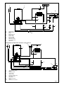
STANDARD HEATING/DHW SYSTEM
2
8
1
A
B
7
9
5
5
6
6
4
4
A
B
1
2
3
4
5
6
7
8
9
Standard CH system
DHW system
Boiler
Expansion tank
System filter
System valve
System pump
Two port valve
DHW thermostat
Room thermostat
DHW tank
4
4
3
HEATING/DHW SYSTEM USING OPTIONAL 3 WAY VALVE KIT
9
8
2
A
1
6
5
4
4
7
10
3
A
1
2
3
4
5
6
7
8
9
10
Standard CH system
Boiler
Expansion tank
System filter
System valve
Heating system pump
Not return valve
DHW tank
Room thermostat
Relay
DHW tank thermostat
Fig. 21
17
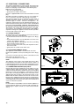
4.7 ELECTRICAL CONNECTIONS
The boiler is supplied with a 2-metre fly-lead. This lead can be
used for connection to the electrical supply. Connect the flylead to a fused plug or fused isolator in the following way:
• brown wire to LIVE supply
• blue wire to NEUTRAL supply
• green/yellow to EARTH connection.
Insert the supplied 3-AMP fuse into the fused isolator or fused
plug.
Should the fly-lead be unsuitable, refer to 4.7.3 for details on
how to connect the electrical supply directly to the boiler.
The electrical supply must be as specified in section 3/3A. A
qualified electrician should connect the appliance to the
electrical supply. If controls - external to the appliance - are
required, a competent person must undertake the design of any
external electrical circuits, please refer to section 8 for detailed
instructions. ANY EXTERNAL CONTROL OR WIRING MUST
BE SERVED FROM THE SAME ISOLATOR AS THAT OF THE
APPLIANCE. The supply cable from the isolator to the appliance must be 3-core flexible sized 0.75mm to BS 6500 or
equivalent. Wiring to the appliance must be rated for operation
in contact with surfaces up to 90 ºC.
4.7.1 CASING REMOVAL
To gain internal access to the appliance you must first remove
the casing, proceed as outlined below:
• locate and unscrew the 3-screws of the upper cover A (fig.
22)
• locate and unscrew the 3-screws (B) that secure the outer
casing to the appliance (fig. 23)
• lift the casing upward to disengage it from the top locating
hooks and then remove (fig. 24)
• store the casing and screws safely until required. Re-fit in
the reverse order
• gently lower the control fascia until it rests.
4.7.2 APPLIANCE TERMINAL BLOCK
The appliance terminal block is located under the shelf.
Remove the hydraulic cover by loosening the screw A (fig.
23)
Loosen the screw that fixes the electric connection box and
than remove the box from its seat.
Locate the terminal block cover (fig. 25).
NOTE
The appliance comes with a factory fitted link (‘TA’) to allow
basic operation of the boiler via the mode selector switch. If it
is anticipated that external controls will be required please refer
to the wiring diagrams in section 8 for more detailed information.
4.7.3 CONNECTING THE MAINS (230V) INPUT
Unhook and remove the terminal block cover (230V). Pass the
cable through the cable anchorage point. Connect the supply
cable wires (LIVE, NEUTRAL, & EARTH) to their corresponding
terminals (L, N, & E) on the appliance – high voltage – terminal
block. When connecting the EARTH wire, ensure that it’s left
slightly longer that the others, this will prevent strain on the
EARTH wire should the cable become taut. Do not remove the
link wire unless additional external controls are to be fitted (see
section 8). The securing screw on the cable anchorage should
now be tightened. This must be done before the terminal block
cover is re-fitted in its position.
NOTE
It is the installer’s responsibility to ensure that the appliance is
properly Earthed. Vokèra Ltd. cannot be held responsible for
any damages or injuries caused as a result of incorrect Earth
wiring.
A
Fig. 22
A
Fig. 23
B
Fig. 24
230 V
low Voltage
Fig. 25
18
SECTION 5 - COMMISSIONING
Inspect the entire installation including the gas meter, test for
tightness and purge. Refer to BS 6891 (I.S. 813 in ROI) for
specific instruction.
• ensure the system has been filled, vented and the pressure
set to 1.5 BAR;
• ensure the flue system has been fitted properly and in
accordance with the instructions;
• ensure all appliance service valves are open.
5.2 THE HEATING SYSTEM
5.6 INITIAL LIGHTING
The appliance contains components that may become
damaged or rendered inoperable by oils and/or debris that
are residual from the installation of the system, consequently
it is essential that the system be flushed in accordance with
the following instructions.
Ensure the electrical supply to the appliance is switched on.
Ensure any external controls are switched to an ‘ON’ position
and are calling for heat. Move the selector switch to the ON
position, the appliance will now operate as described in 1.2.
Should the appliance fail to ignite, refer to 5.6 and/or section 7
(mode of operation, parameter setting & faultfinding).
5.1 GAS SUPPLY INSTALLATION
5.3 INITIAL FILLING OF THE SYSTEM
Ensure both flow and return service valves are open, remove
appliance casing as described in 4.7.1, identify the automatic
air release valves (AAV) and loosen the dust cap/s by turning
the cap anti-clockwise one full turn. Ensure all manual air
release valves located on the heating system are closed.
Connect the filling loop, slowly proceed to fill the system by
firstly opening the inlet valve connected to the flow pipe, and
then turning the lever on the fill valve, to the open position. As
water enters the system the pressure gauge will begin to rise.
Once the gauge has reached 1.5 BAR close both valves and
begin venting all manual air release valves, starting at the lowest
first. It may be necessary to go back and top-up the pressure until
the entire system has been filled. Inspect the system for water
tightness, rectifying any leaks.
5.3.1 MANUAL AIR RELEASE (fig. 26)
When the boiler has been filled for the first time or the system
has been drained and refilled, it will be necessary to release
any air that may have become trapped within the appliance
heat exchanger. Slacken the bleed screw until water is
released and then close.
IMPORTANT, THERE ARE NO OTHER MANUAL AIR
RELEASE VALVES LOCATED ON THE APPLIANCE.
5.7 CHECKING GAS PRESSURE AND COMBUSTION ANALYSIS
The appliance is factory set and requires no additional
adjustment once installed. However to satisfy the requirements
of GSIUR 26/9 (I.S. 813 ROI), it will be necessary to gas rate the
appliance using the gas meter that serves the appliance.
If the installation does not include a gas meter (for example
LPG) and there are no means by which to calculate the gas rate,
then a combustion analysis test must be carried out in
accordance with BS 7967 (UK) to ensure the appliance is left
working safely and correctly.
Additionally, if the gas valve has been adjusted, replaced, or
the appliance has been converted for use with another gas
type, then it becomes necessary to carry out a combustion
analysis/check to ensure that correct combustion is occurring.
If there are no means to gas rate the appliance and/or carry out
a combustion analysis check, then it will not be possible to
complete the commissioning procedure.
Details on how to carry out the combustion analysis can be
found in section 7.
IMPORTANT
It’s imperative that a sufficient dynamic – gas – pressure is
maintained at all times. Should the dynamic gas pressure fall
below an acceptable level, the appliance may malfunction or
sustain damage.
5.8 FINAL FLUSHING OF THE HEATING SYSTEM
The system shall be flushed in accordance with BS 7593 (I.S.
813 ROI). Should a cleanser be used, it must be suitable for
Aluminium heat exchangers. It shall be from a reputable manufacturer and shall be administered in strict accordance with
the manufacturers’ instructions and the DWTA code of practice.
NOTE
Chemicals used to cleanse the system and/or inhibit corrosion
must be pH neutral, i.e. they should ensure that the level of the
pH in the system water remains neutral. Premature failure of
certain components can occur if the level of pH in the system
water is out-with normal levels.
5.8.1 INHIBITORS
See Section 3 “General Requirements”.
Fig. 26
5.4 INITIAL FLUSHING OF THE SYSTEM
The whole of the heating system must be flushed both cold and
hot as detailed in 5.8. Open all radiator or heating valves and
the appliance flow & return service valve. Drain the boiler and
system from the lowest points. Open the drain valve full bore to
remove any installation debris from the boiler prior to lighting.
Refill the boiler and heating system as described in 5.3.
5.5 PRE-OPERATION CHECKS
Before attempting the initial lighting of the appliance, the
following checks must be carried out:
• ensure all gas service valves from the meter to the appliance
are open and the supply pipe has been properly purged;
• ensure the proper electrical checks have been carried out,
(see 7.9) particularly continuity, polarity and resistance to
earth;
• ensure the 3 AMP fuse – supplied with the appliance – has
been fitted;
5.9 SETTING THE FLOW OUTLET TEMPERATURE
The flow outlet temperature can be adjusted between 40 °C
- 80 °C for standard CH system and between 20 °C - 45 °C
for under-floor systems by using the Heating thermostat
knob (see fig.1). For further details consult “Boiler
configuration” section.
5.10 SETTING
PRESSURE
THE
SYSTEM
DESIGN
The design pressure should be a minimum of 0.5 BAR and a
maximum of 2.0 BAR. The actual reading should ideally be 1.5
BAR plus the equivalent height in metres (0.1 BAR = 1 metre)
to the highest point in the system above the base of the
appliance (up to the maximum of 2.0 BAR total).
N.B. The safety valve is set to lift at 3.5 BAR/35 metres/45 psig.
To lower the system pressure to the required value, drain off
some water from the appliance drain valve until the required
figure registers on the pressure gauge (see fig. 1).
19
5.11 REGULATING THE CENTRAL HEATING
SYSTEM
Fully open all radiator and circuit valves and run the appliance
for both heating and hot water until heated water is circulating.
If conditions are warm remove any thermostatic heads. Adjust
radiator return valves and any branch circuit return valves
until the individual return temperatures are correct and are
approximately equal.
5.12 FINAL CHECKS
• ENSURE ALL TEST NIPPLES ON THE APPLIANCE GAS
VALVE ARE TIGHT AND CHECKED FOR TIGHTNESS.
• ENSURE THE APPLIANCE FLUE SYSTEM IS FITTED
CORRECTLY AND IS PROPERLY SECURED.
• ENSURE ALL PIPE WORK IS RE-CHECKED FOR
TIGHTNESS.
• RE-FIT APPLIANCE CASING.
• COMPLETE BENCHMARK CHECKLIST.
FOR UK ONLY
Complete details of the boiler, controls, installation and
commissioning in the Benchmark checklist at the back of this
book. It is important that the Benchmark checklist is correctly
completed and handed to the user. Failure to install and commission the appliance to the manufacturers instructions may
invalidate the warranty.
5.13 INSTRUCTING THE USER
Hand over all documentation supplied with this appliance –
including these instructions – and explain the importance of
keeping them in a safe place.
Explain to the user how to isolate the appliance from the gas,
water and electricity supplies and the locations of all drain
points. Show the user how to operate the appliance and any
associated controls correctly.
Show the user the location of the filling valve and how to topup the system pressure correctly and show the location of all
manual air release points.
Explain to the user how to turn off the appliance for both long
and short periods and advise on the necessary precautions
to prevent frost damage.
Explain to the user that for continued safe and efficient operation,
the appliance must be serviced annually by a competent
person.
IMPORTANT
To validate the appliance warranty, it’s necessary to register
the appliance details with us. The warranty can be registered
in several ways:
• by completing the warranty registration card and posting to
us using the envelope supplied
• online at: vokera.co.uk
• for UK residents by calling: 0870 607 0281
• for ROI residents by calling: 056 6655057.
20
SECTION 6 - SERVICING INSTRUCTIONS
6.1 GENERAL
To ensure the continued safe and efficient operation of the
appliance, it is recommended that it is checked and serviced
at regular intervals. To ensure correct and safe operation of
the appliance, it is essential that any worn or failed component be replaced only with a genuine Vokèra spare part. It
should be remembered that although certain generic
components may look similar, they will be specific to an
individual appliance or product range. Use of non-genuine
Vokèra spare parts could invalidate your warranty and may
pose a potential safety hazard. The frequency of servicing will
depend upon the particular installation conditions, but in
general, once per year should be sufficient. It is the law that
any servicing work is carried out by competent person such
as a Vokèra engineer, an approved service agent, British Gas,
GAS SAFE registered personnel or other suitably qualified
personnel. The following instructions apply to the appliance
and its controls, but it should be remembered that the central
heating and the domestic hot water systems would also require
attention from time to time.
6.2 ROUTINE ANNUAL SERVICING
• Check the operation of the appliance and ensure it functions
as described in section 7.
• Compare the performance of the appliance with its design
specification. The cause of any noticeable deterioration
should be identified and rectified without delay.
• Thoroughly inspect the appliance for signs of damage or
deterioration especially the flue system and the electrical
apparatus.
• Check and adjust – if necessary – all burner pressure
settings (see 7.4).
• Check and adjust – if necessary – the system design pressure
(see 5.10).
• Carry out an analysis of the flue gases (see 7.5), and visually
check the condition of the entire flue assembly.
• Compare the results with the appliance design specification.
Any deterioration in performance must be identified and
rectified without delay.
• Check that the burner and main heat exchanger are clean and
free from any debris or obstruction.
• Check and clean – if necessary – the condense trap to ensure
correct operation.
Fig. 27
6.6 SAFETY VALVE (fig. 28)
Carry out component removal procedure as described in 6.4.
Disconnect the outlet pipe (A) from the safety valve, remove
safety valve locking pin (B) from the hydraulic manifold. Replace
in the reverse order.
B
A
Fig. 28
6.7 TOP AUTOMATIC AIR RELEASE VALVE
(fig. 29)
Carry out component removal procedure as described in 6.4.
Remove the AAV locking pin (C) from the deaerator assembly
and remove the AAV assembly (D). Replace in the reverse
order.
D
6.3 REPLACEMENT OF COMPONENTS
Although it is anticipated that this appliance will give years of
reliable, trouble free service, the life span of components will
be determined by factors such as operating conditions and
usage. Should the appliance develop a fault, the fault finding
section will assist in determining which component is
malfunctioning.
C
6.4 COMPONENT REMOVAL PROCEDURE
To remove a component, access to the interior of the appliance
is essential. Isolate the appliance from the electrical supply
and remove the fuse. And when necessary, close all service
valves on the appliance, remove the appliance casing as
described in section 4.7.1 and drain the water content from
the appliance via the drain valve. Ensure some water
absorbent cloths are available to catch any residual water
that may drip from the appliance or removed component. Undertake a complete commissioning check as detailed in section
5, after replacing any component. ALWAYS TEST FOR GAS
TIGHTNESS IF ANY GAS CARRYING COMPONENTS HAVE
BEEN REMOVED OR DISTURBED.
Fig. 29
6.8 WATER PRESSURE SWITCH (fig. 30)
Carry out component removal procedure as described in 6.4.
Locate and remove the locking pin (E) from the water pressure
switch (F). Remove the wiring. Carefully withdraw the switch.
Replace in the reverse order.
E
6.5 PUMP ASSEMBLY (fig. 27)
Carry out component removal procedure as described in 6.4.
Slacken and unscrew pump inlet and outlet connectors.
Please note the sealing washers must be discarded and
replaced with new sealing washers.
The pump assembly can now be removed from the appliance.
Replace carefully in the reverse order.
F
Fig. 30
21
6.9 FLOW THERMISTOR (fig. 3 - pos. 18)
Carry out component removal procedure as described in
6.4.Unclip the flow thermistor from the flow outlet pipe. Disconnect
thermistor electrical plug. Replace in the reverse order.
6.10 RETURN THERMISTOR (fig. 3 - pos. 8)
Carry out component removal procedure as described in 6.4.
Unclip the return thermistor from the return inlet pipe. Disconnect
thermistor electrical plug. Replace in the reverse order.
6.11 PRINTED CIRCUIT BOARD (fig. 31)
Carry out component removal procedure as described in 6.4.
Pull the control fascia forward and lower it. Push the clips (G)
which secure the PCB cover, remove cover, after carefully
taking note of all wiring connections and jumper tag configuration. Unhook and remove connection block (H). Disconnect
all wiring from the PCB, locate and remove the PCB securing
screws, remove the required PCB. Replace in the reverse
order ensuring that the position of the 2 control knobs are
correctly aligned with the respective potentiometers on the
PCB.
Ensure that the correct jumper tag configuration has been
respected. It will be necessary to check the functioning of the
PCB is set for the correct boiler type/application.
G
H
Fig. 31
6.12 GAS VALVE (fig. 32)
Carry out component removal procedure as described in 6.4.
The gas valve must be changed as complete unit. Disconnect
the electrical plug and leads from the gas valve, slacken and
unscrew gas valve inlet and outlet connections. Please note,
the sealing washers (i) must be discarded and replaced with
new sealing washers. Disconnect the compensation pipe (L).
Unscrew gas pipe connections (M-N), the gas valve can now
be removed. Replace in the reverse order. Check and adjust
burner pressure settings.
WARNING, A GAS TIGHTNESS CHECK MUST BE CARRIED
OUT.
6.12.1 INJECTOR (fig. 32)
Carry out component removal procedure as described in 6.4.
Unscrew and remove gas pipe connections (M-N). Locate and
remove the injector (O) inside the upper connection pipe.
Replace in the reverse order. Check and adjust burner pressure
settings.
WARNING, A GAS TIGHTNESS CHECK MUST BE CARRIED
OUT.
M
I
O
N
I
L
Fig. 32
6.13 ELECTRODES (fig. 33)
Carry out component removal procedure as described in 6.4.
Disconnect the electrode leads and ancillary wiring from their
respective connectors. Remove the retaining screws (P) for
electrode. Remove the spark ignition (Q) and sensing (R)
electrodes (W). Remove the retaining nut (S) for condense
sensor (T) an dremove.
R
S
P
S
Fig. 33
22
T
6.14 FLUE FAN (fig.34)
Carry out component removal procedure as described in 6.4.
Disconnect the ancillary wiring from their respective connectors.
Remove the retaining screws (U) to disconnect mixer, Remove
the retaining screws (V) and remove fan. Replace in the reverse
order.
6.15 MIXER (fig. 35)
Carry out component removal procedure as described in 6.4.
Disconnect jubilee clip (W) and remove flexible air duct,
Disconnect gas pipe from mixer, remove the retaining screws
(X) and remove mixer. Replace in the reverse order.
WARNING, A GAS TIGHTNESS CHECK MUST BE CARRIED
OUT.
U
Fig. 34
V
6.16 BURNER (fig. 36)
Carry out component removal procedure as described in 6.4.
Disconnect jubilee clip and disconnect flexible air duct.
Disconnect gas pipe from mixer, disconnect the electrode as
described in 6.13.
Remove the retaining nuts and gently ease the fan assembly
out of its location. Once the assembly has been removed, the
burner can be withdrawn from the heat engine. Ensure the seal
is in good condition, taking care to ensure it is replaced
correctly.
Replace in the reverse order.
W
X
Fig. 35
6.17 MAIN HEAT EXCHANGER (fig. 37)
Carry out component removal procedure as described in 6.4.
Disconnect all the wiring connections.
Disconnect the gas pipe at the air mixer connection.
Disconnect the flow, return and condense connections on the
heat exchanger.
Locate and remove the 4-screws that secure the heat exchanger
to the combustion chamber (D). Move the heat exchanger to the
right and disconnect it from the flue collector. The heat exchanger
and fan assembly can now be lifted up and withdrawn from the
appliance.
Fig. 36
23
D
Fig. 37
6.18 CONDENSE TRAP AND COLLECTOR
REMOVAL (fig. 38)
Carry out component removal procedure as described in 6.4.
Disconnect the 2 upper rubber condense pipes. Remove the
pin (B) that secures the trap to the chassis. Disconnect the
lower rubber condense pipe from the condense trap. Remove
the pins (D) that secures the collector to the exchanger.
Carefully remove the condense trap and collector. Replace
in the reverse order.
D
Fig. 38
6.20 FLUE COLLECTOR REMOVAL (fig. 39)
Z1
Carry out component removal procedure as described in 6.4.
Disconnect the rubber condense pipe, disconnect the
thermistor wiring connection, disconnect the analysis test
point (Z1), unscrew the retaining bar from the exchanger, pull
the upper retaining bar to the left, pull the flue collector down
and to the right to remove. Ensure the seal is in good condition,
taking care to ensure it is replaced correctly. Replace in the
reverse order.
Y1
Fig. 39
24
B
SECTION 7 - CHECKS, ADJUSTMENTS AND FAULT FINDING
7.1 CHECKING APPLIANCE OPERATION
When carrying out any repairs or servicing to the appliance, the
relevant commissioning procedure must be undertaken to
ensure the continued safe operation of the appliance. Particular
attention should be made to ensure gas tightness, water
tightness and the electrical integrity of the appliance.
7.2 APPLIANCE MODES OF OPERATION
NOTE
There must be sufficient system water pressure (min. 0.5 bar)
to ensure the water pressure switch is activated. If there is
insufficient system pressure the pump and fan will be prevented
from operating and the low-pressure fault code will be indicated.
7.2.1 SELECTOR SWITCH IN THE OFF/RESET POSITION
When the selector switch is in the OFF/RESET position, the
following functions are active.
Active functions:
• frost-protection system
• pump anti-block.
7.2.2 ON-BOARD FUNCTIONS
• CO FUNCTION: the CO function when activated, will allow
the appliance to run at CH maximum, whilst a combustion
analysis check or a mechanical gas valve calibration is being
carried out. Whilst the CO function is active, all other functions
are disabled (minimum power operating period, anti-cycle,
set-point, etc). Once enabled, the CO function will remain
active for a 15-minute period, or until the function is manually
deactivated.
• FROST-PROTECTION: this function is only active when
there are no requests for heating or HW. If the temperature
drops below 5°C, the boiler will operate on minimum power
until the temperature of the thermistors reaches 35°C .
Thereafter the pump & fan will over-run for 30-seconds.
• ANTI-CYCLE FUNCTION: the anti-cycle function ensures
the burner remains switched off for at least 3-minutes after the
set-point hysterisis (set-point + 5-deg) for CH heat request.
• PUMP ANTI-BLOCK FUNCTION: when there has been no
heating or HW request for 24-hours, the anti-block cycle is
activated. The pump will be activated for a period of 30seconds.
• PUMP CYCLE MODE: when power is restored to the PCB
and/ or the PCB is powered for the first time, the appliance
will enter a 2-minute purge cycle whereby only the pump will
run for 15-seconds then off for 15-seconds and will not “fire”
until this period has elapsed.
• ACTUATOR ANTI-BLOCK FUNCTION: when there has been
no heating or HW request for 24- hours, the anti-block cycle
is activated. The divertor valve actuator will motor briefly to
the heating position, and then back to the DHW position.
• SARA function: the SARA function permits the boiler (when
the set-point is within the SARA range) to automatically
adjust (raise) the heating flow outlet temperature should the
room thermostat contacts remain closed for more that 20minutes.
the flow sensor results in a lower fan speed. As the water
temperature increases, the temperature sensors – located
on the flow pipe of the boiler – reduce the fan speed via the
electronic circuitry. Depending on the load, either the water
temperature will continue to rise until the set point is
achieved or the water temperature will fall whereby fan
speed will increase relative to the output required. When
the boiler has reached the set point (+ hysterisis), the burner
will switch off. The built-in anti-cycle device prevents the
burner from re-lighting for approximately 3-minutes. When
the temperature of the flow sensor falls below the set point
(- hysterisis), the burner will re-light.
7.2.3 HOT WATER (optional 3-way valve kit installed)
With the selector switch in the heating & hot water or hot water
position and tank thermostat calling for heat, the appliance will
operate in hot water mode. The external 3 way valve switches
on tank circuit, the pump and fan will be activated via the flow
temperature sensor. When the fan is sensed to be operating
correctly (tacho signal), the ignition sequence commences.
Ignition is sensed by the electronic circuit to ensure flame
stability at the burner. Once successful ignition has been
achieved.
The speed of the fan and therefore the output of the boiler is
determined by the temperature of the water sensed by the flow
temperature sensor of the boiler, consequently a high
temperature at the flow sensor results in a lower fan speed.
As the water temperature increases, the temperature sensors
– located on the flow pipe of the boiler – reduce the fan speed
via the electronic circuitry. Depending on the load, either the
water temperature will continue to rise until the set point (80 °C)
is achieved or the water temperature will fall whereby fan speed
will increase relative to the output required. When the boiler has
reached the set point (+ hysterisis), the burner will switch off.
When the temperature of the flow sensor falls below the set
point (- hysterisis), the burner will re-light.
When the hot water reaches the desired temperature (tank
thermostat opened) the burner will shut down, the pump is off
and 3-way valve switches on heating circuit.
NOTE
If the spark/sensing electrode does not sense ignition the
appliance will re-attempt ignition a further 4-times then go to
lockout. When the set-point has been reached (the position of
the heating temperature selector) as measured at the primary
thermistor, the appliance will begin the modulation phase
whereby the fan and gas valve will continuously modulate to
maintain the set-point.
ATTENTION
Gas type and appliance output must be set according to the
specific appliance specification. Vokèra accepts no
responsibility if the gas type is not correctly adjusted according
to the respective appliance specification as detailed on the
appliance data badge.
7.2.3 HEATING MODE
With the selector switch in the heating & hot water position
and any additional controls (time clock, programmer, room
thermostat, etc.) calling for heat, the appliance will operate in
the heating mode. The pump and fan will be activated via the
flow temperature sensor. When the fan is sensed to be
operating correctly (tacho signal), the ignition sequence
commences. Ignition is sensed by the electronic circuit to
ensure flame stability at the burner. Once successful ignition
has been achieved, the electronic circuitry increases the gas
rate to 75% for a period of 15 minutes.
The speed of the fan and therefore the output of the boiler is
determined by the temperature of the water sensed by the
flow temperature sensor, consequently a high temperature at
25
7.3 SETTING THE THERMOREGULATION
(Contact Vokera technical for advice if Vokera DHW 3 way
valve kit is not being used)
Heat regulation only works with the external sensor connected,
and so once installed, connect the external sensor to the
relevant connections provided on the terminal board in the
boiler.
This enables the HEAT REGULATION function.
Tshift =
30°C standard plants
25°C floor-standing plants
If the calculation gives an intermediate value between two
curves, we recommend choosing the compensation curve
closest to the value obtained.
Example: If the calculation produces a value of 1.3, this lies
between the 1 and 1.5 curves. In this case choose the closest
curve, that is 1.5.
The KT selection must be done using trimmer P3
on the board (see multi-line wiring diagram). To access P3:
- Remove the casing
- Turn the control panel towards you
- Unhook the board cover
Thermoregulation curves
DELIVERY TEMPERATURE (°C)
Choosing the compensation curve
The heating compensation curve provides for maintaining a
theoretical ambient temperature of 20°C for outside
temperatures of between +20°C and –20°C. The choice of the
curve depends on the minimum outside design temperature
(and therefore the geographical location) and the design
delivery temperature (and therefore the type of plant) and is to
be calculated carefully by the installer, using the following
formula:
KT= T. design delivery - Tshift
20- T. min external design.
37,5 32,5
40
35
30 27,5 25
100
22,5
20
90
17,5
80
70
15
P.21
12,5
60
10
50
7,5
40
5
30
2,5
P.22
20
20
15
10
5
0
-5
-10
-15
-20
EXTERNAL TEMPERATURE (°C)
T80
maximum heating temperature set point - standard plants (JP7 not inserted)
T45
maximum heating temperature set point - floor-standing plants (JP7 inserted)
Live electrical parts (230 Vac).
If the boiler has a timer programmer connected to it
(JUMPER JP6 inserted)
When the contact is closed, the heat request is made by the
delivery sensor, based on the outside temperature, to have a
nominal ambient temperature at the DAY level (20°C). Opening
of the contact does not switch the boiler off but reduces the
climatic curve (by parallel translation) to the NIGHT level (16
°C
This is how the night-time function is activated.
The delivery temperature is calculated automatically by the
boiler, however, the user can interact with the boiler.
When interacting with the interface to change HEATING you
will not have the HEATING SET POINT value available, but a
value that can be set as you wish between +5 and -5°C.
Changing this value does not directly change the delivery
temperature but affects the calculation that determines this
value automatically, by changing the reference temperature
system (0 = 20°C, for the DAY level; 16 °C for the NIGHT level).
26
DELIVERY TEMPERATURE (°C)
TYPE OF HEAT REQUEST
If the boiler has an ambient thermostat connected to it
(JUMPER 6 not inserted)
The heat request is made by the ambient thermostat’s contact
closing, and when the contact opens it switches it off. The
delivery temperature is calculated automatically, however, the
user can interact with the boiler. When the interface is used to
change HEATING the value of the HEATING SET POINT will
not be available, but a value that can be set as you wish
between +5 and -5°C. Changing this value does not change
the delivery temperature directly, but acts in the calculation that
determines the value automatically, changing the reference
temperature in the system (0 = 20°C).
Temperature curve correction
90
80
70
60
50
40
30
+5˚C
20
10
30
0˚C
25
-5˚C
20
15
10
5
0
-5
-10
-15
-20
EXTERNAL TEMPERATURE (°C)
Parallel night reduction
DELIVERY TEMPERATURE (°C)
The KT values that can be set are as follows: standard plant:
1,0-1,5-2,0-2,5-3,0 floor-standing plant 0,2-0,4-0,6-0,8
and these will be shown on the display for about 3 seconds after
trimmer P3 is turned.
90
DAY
80
70
temperature curve
60
50
NIGHT
40
temperature curve
30
20
10
20
15
10
5
0
-5
-10
EXTERNAL TEMPERATURE (°C)
-15
-20
7.4 CHECKING/ADJUSTING THE APPLIANCE
FAN SPEEDS
The boiler has already been set during fabrication by the
manufacturer. However, if it is necessary to set it again, after
extraordinary maintenance work for example, after replacing
the gas valve, or after switching from natural gas to LPG,
follow the procedures described below. The maximum and
minimum power, the maximum heating and slow ignition
setting must strictly be done in the sequence indicated and
only by qualified personnel:
- Disconnect the power supply to the boiler.
- Turn the heating water temperature selector to the maximum
value, that is the selector turned to the 10
- Then lift and rotate the control panel towards you
- Remove the board cover by releasing the fixing hooks.
- Insert jumpers JP1 and JP3 (fig. 41)
- Put the power to the boiler on.
The three LEDs on the control panel flash simultaneously
and the display reads “ADJ” for about 4 sec.
Proceed to modify the following parameters:
1 Absolute maximum
2 Minimum
3 Maximum heating
4 Slow ignition
as described below:
- Turn the heating water temperature selector to set the value
required.
- Press the CO button (SW1) and move on to setting the next
parameter.
Live electrical parts (230 Vac).
The following icons switch on on the display:
1.
During absolute maximum setting (MAX)
2.
During minimum setting (MIN)
3.
During maximum heating setting (HTG)
4.
During slow ignition setting (IGN)
L2
SW1
use the supplied
screwdriver to push
the CO botton (SW1)
Fig. 40
End the procedure by removing jumpers JP1 and JP3 to save
the values set in this way.
The procedure can be ended at any time without saving the
values set and keeping the initial settings:
- Turning the function selector to “
“ OFF/RESET
- Switching off the mains power supply
- After a delay of 15 min after switching it on.
Fig. 41
Setting does not switch on the boiler.
When the heating selector knob is turned the display
automatically shows the number of RPM expressed in
hundreds (e.g. 25 = 2500 rpm).
Fan speed (rpm) table
MAX
MIN
HTG
IGN
5800
1400
5800
3000
7.5 CHECKING THE CO2 AND ADJUSTING THE
GAS VALVE
THE GAS VALVE MUST BE SET-UP OR ADJUSTED WITH
THE AID OF A PROPERLY CALIBRATED FLUE GAS
ANALYSER.
Isolate the appliance from the electrical supply and remove the
appliance casing as described in 4.7.1. Set the flue gas
analyser to read CO2 and insert the probe into the flue analysis
test point (Y1-Z1 fig. 39). Restore the electrical supply to the
boiler and switch the boiler to the OFF mode.
Have access to the printed circuit board, locate and open the
closing plug on the dash board (L2 - fig. 40), locate and press
the CO button (see fig. 40 pos. SW1). The display shows “ACO”
and the yellow led blinks.
Press the button the number of timing according the function
requirement as par 7.5.1.
27
7.5.1 CO2 FUNCTION SETTINGS
Locate the CO button (see 7.3)
Select the main selector switch in position
CO2 FUNCTIONS
ACTION ON THE BUTTON
LED STATUS
combustion analysis mode
press once = burner running at maximum heating
yellow led blinking
gas valve maximun setting (*)
press twice = burner running at maximum absolute
yellow led blinking + red led fixed
gas valve minimum setting
press three time = burner running at minimum
yellow led blinking + green led fixed
(*) this step has not to be used for the system boiler. If you find in this situation press the button once again.
NOTE
1 - Any additional pressing of CO button after the third time the burner switched between maximum absolute and minimum.
2 - To restart the CO function it is necessary to pass throught the
7.5.2 GAS VALVE MAXIMUM SETTING
Set the CO2 button at maximum absolute (see 7.5.1), once the
maximum absolute is obtained (yellow led blinking + red led
fixed) check that it corresponds with the appropriate CO2 value
(Maximum) for the respective appliance (see 2.11). If the CO2
reading is correct, proceed to gas valve minimum setting
(7.5.3).
However, if the CO2 reading is incorrect, the maximum gas
pressure must be adjusted as follows:
• using a 2.5mm Allen key, very slowly turn the maximum
adjustment screw (see fig. 42) – clockwise to decrease,
counter clockwise to increase – until the correct value is
displayed on the CO2 analyser (allow time for the analyser
to stabilise).
7.5.3 GAS VALVE MINIMUM SETTING
Set the CO2 button at minimum (see 7.5.1), once the minimum
is obtained (yellow led blinking + green led fixed) check that it
corresponds with the appropriate CO2 value (Minimum) for
the respective appliance (see 2.11). If the CO2 reading is
correct, proceed to completion (7.5.4).
However, if the CO2 reading is incorrect, the minimum gas
pressure must be adjusted as follows:
• locate the minimum adjustment screw (fig. 42), using a
suitable screwdriver remove the protection plug
• using a 4mm Allen key, very slowly turn the minimum
adjustment screw (see fig. 42 - clockwise to increase, counter
clockwise to decrease - until the correct value is displayed on
the CO2 analyser (allow time for the analyser to stabilise).
position with the main selector switch
maximum
adjustment screw
compensation
pipe connection
minimum
adjustment screw
Inlet gas pressure
connection
fig. 42
CO2 @ maximum output (%)
CO2 @ minimum output (%)
7.5.4 COMPLETION
On completion of the combustion analysis check and/or any
gas valve adjustment, refit the plug (fig. 40 L2) and move the
position. Remove the test probe
mode selector throught
from the test point and refit the sealing screw/s and/or cap.
IMPORTANT
A GAS TIGHTNESS CHECK MUST BE CARRIED OUT IF ANY
GAS CARRYING COMPONENTS HAVE BEEN REMOVED,
7.6 RANGE RATED
This boiler can be adapted to the plant’s thermal need, in fact,
the maximum flow rate can be set for the boiler’s heating
function:
- Disconnect the power supply to the boiler.
- Turn the heating water temperature selector to the maximum
value, that is the selector turned to 10
- Lift and rotate the control panel towards you
- Remove the cover by releasing the fixing hooks.
- Insert jumper JP1 (fig. 43)
- Put the power to the boiler on.
The three LEDs on the control panel flash alternately and an
“ADJ” message is shown on the display for about 4 sec, after
which the maximum heating value can be changed using the
heating temperature selector and SW1(CO) button to set and
.
confirm the required value. The display shows the icon
End the procedure by removing jumper JP1 to save the values
set in the memory.
28
fig. 43
NATURAL GAS
9.0
9.5
LPG
10,0
10,0
Once the required (maximum heating) power is set indicate the
value on the instruction manual (see back cover). For
subsequent checks and adjustments, see the value set.
Setting does not switch on the boiler. When the heating setpoint selector knob is turned the display automatically shows
the number of rpm expressed in hundreds (e.g. 25 = 2500 rpm).
The boiler is supplied with the settings shown in the table.
However, this value can be adjusted based on plant needs or
regional regulations on combusted gas emission limits, by
referring to the graphs shown below.
Emissions COs.a. (p.p.m.) G20
Emissions curve (heating Qn)
200
190
180
170
160
150
140
130
120
110
100
90
80
70
60
50
40
30
20
10
0
8
10
12
14
16
18 20 22 24 26 28 30 32
Portata
termica riscaldamento (kW)
34
36
38
40
42
44
46
48
Nominal input (kW)
HTG curve (heating Qn)
6000
5600
5200
HTG fan r.p.m.
4800
4400
4000
3600
3200
2800
2400
2000
1600
1200
8
10
12
14
16
18
20
22
24
26
28
30
32
34
36
38
40
42
44
46
48
Nominal input (kW)
REPLACED OR DISTURBED.
7.7 COMBUSTION ANALYSIS TEST
A combustion analysis check can easily be carried out on the
appliance via the test points located on the top of the appliance
(see 7.5).
• Insert the flue gas analyser probe into the flue gas test point
(pos. 11 - fig. 3).
• Operate the boiler in combustion analysis mode (see 7.5.1)
and compare the values with those shown in section 2 (Nat.
Gas) or section 10 (LPG). If different adjust the gas valve
according to 7.5.1, 7.5.2, & 7.5.3.
29
7.8 EXTERNAL FAULTS
Before carrying out any faultfinding or component replacement,
ensure the fault is not attributable to any aspect of the installation.
7.8.1 INSTALLATION FAULTS
Symptom
No led/ignition
No hot water
No heating
Fault
Red led fixed
Possible cause
Check wiring/check electrical
supply
Check pipe-work
Check external controls
Possible cause
Check gas supply, check flue
system, check polarity
7.9 ELECTRICAL CHECKS
Any electrical checks must be carried out by a suitably qualified
person.
7.9.1 EARTH CONTINUITY TEST
Isolate the appliance from the electrical supply, and using a
suitable multi-meter carry out a resistance test. Connect test
leads between an appliance earth point and the earth wire of
the appliance supply cable. The resistance should be less than
1 OHM. If the resistance is greater than 1 OHM check all earth
wires and connectors for continuity and integrity.
7.9.2 SHORT CIRCUIT CHECK
Isolate the appliance from the electrical supply, and using a
suitable multi-meter, carry out a short circuit test between the
Live & Neutral connections at the appliance terminal strip.
Repeat above test on the Live & Earth connections at the
appliance terminal strip.
NOTE
Should it be found that the fuse has failed but no fault is
indicated, a detailed continuity check will be required to trace
the fault. A visual inspection of components may also assist in
locating the fault.
7.9.3 POLARITY CHECK
With the appliance connected to the electrical supply and using
a suitable multimeter, carry out the following voltage tests:
• connect test leads between the Live & Neutral connections
at the appliance terminal strip. The meter should read
approximately 230V ac. If so proceed to next stage. If not, see
7.9.4.
• connect test leads between the Live & Earth connections at
the appliance terminal strip. The meter should read
approximately 230V ac. If so proceed to next stage. If not, see
7.9.4.
• connect test leads between the Neutral & Earth connections
at the appliance terminal strip. The meter should read
approximately 0 – 15Vac. If so polarity is correct. If not, see
7.9.4.
7.9.4 REVERSED POLARITY OR SUPPLY FAULT
Repeat the above tests at the appliance isolator, if testing
reveals correct polarity and/or supply at the isolator, re-check
wiring and connections between the isolator and the appliance.
If tests on the isolator also reveal reversed polarity or a supply
fault, consult the local electricity supplier for advice.
7.9.5 RESISTANCE TO EARTH CHECK
Isolate the appliance from the electrical supply, and using a
suitable multi-meter carry out a resistance test. Connect test
leads between the Live & Earth connections at the appliance
terminal strip. If the meter reads other than infinity there is a fault
that must be isolated, carry out a detailed continuity check to
identify the location of the fault.
These series of checks must be carried out before attempting
any faultfinding procedures on the appliance. On completion
of any task that required the disconnection and re-connection
of any electrical wiring or component, these checks must be
repeated.
Disconnect any external controls from terminal plug (CN5 fig.
47), and insert a link-wire between the two wires at the ‘TA’
connections.
30
7.10 COMPONENT
VALUES
CHARACTERISTICS
&
COMPONENT
Fan
Pump
Ignition transformer
Gas valve
Room thermostat connection
NTC thermistor (dry contact)
NTC thermistor (wet contact)
VALUE
230Vac
230Vac
230Vac
230Vac
24Vdc
10Kohm
10Kohm
FUNCTION
Standard Heating temperature
range (min – max °C)
Floor Heating temperature
range (min – max °C)
75% maximum CH time
Heating OFF hysterisis (°C)
Heating ON hysterisis (°C)
Anti-cycle delay
Pump over-run
Low output (min. output + %)
CO function max temp. (°C)
CO re-light temp. (°C)
CO function time
Flow NTC max temp. (°C)
High limit thermostat (°C)
Flue NTC max temp. (°C)
Maximum differential (°C)
VALUE
IGNITION CONTROL
Ignition attempts before L/O (lockout)
Re-ignition attempts after loss
of flame signal
40 - 80
20 - 45
15 min
SP + 5
SP – 5
3-min
30-sec
Min+25
90
78
15-min
90
105
125
35
VALUE
5
5
7.11 APPLIANCE STATUS LED AND FAULT
CODES
When the boiler detects a temporary fault condition, the
appropriate led indication is shown. If/when the fault is final,
the pump will perform a 60-second post circulation and red
LED will be illuminated. See table on pag. 4.
Fault A 09 with the green and red LEDs flashing
The boiler has a self-diagnosis system that is able, based on
the hours totalled under particular operating conditions, to
indicate the need for cleaning of the primary exchanger
(alarm code 09 with green and red LEDs flashing and the
fume sensor counter > 2,500).
Once cleaning has been completed, using the specific kit
supplied as an accessory, the counter for the totalled hours
must be reset, using the following procedure:
- Disconnect the electrical power supply
- Remove the casing and turn the control panel around
- Remove the board cover
- While applying the electrical power supply to the boiler,
press the CO button for at least 4 seconds to check that the
counter has been reset and put the power to the boiler on
again. The display shows the value for the counter after
indicating “-C-”.
Live electrical parts (230 Vac).
Note: The counter resetting procedure must be done after
each thorough cleaning of the primary exchanger or if it is
replaced. To check the status of the hours totalled, multiply
the value read by 100 (e.g. value read 18 = 1800 hours totalled
- value read 1 = 100 hours totalled).
The boiler continues to function normally even when this
alarm is active.
7.12 BOILER CONFIGURATION
The electronic board has a series of jumpers on it (JPX)
that are used to configure the boiler.
Access to the board as follows:
- Turn the plant’s main switch off.
- Unscrew the fixing screws for the casing, move it forward and
then down to disconnect it from the chassis.
- Then lift and rotate the control panel towards you
- Remove the cover by releasing the fixing hooks.
JUMPER JP7:
Pre-selection of the heating temperature adjustment range
that is most suitable for the type of plant.
Jumper not inserted - standard plant
Standard plant 40-80°C
Jumper inserted - floor-standing plant
Floor-standing plant 20-45°C
During fabrication the boiler was configured for standard
plants.
JP1 Enabling front setting knobs (Range Rated)
JP2 Resetting heating timer
JP3 Setting (see “checking and adjusting” paragraph)
JP4 Unused
JP5 do not use - closed
JP6 Enabling night-time compensation function and pump
continuously (only with external sensor connected)
JP7 Enabling standard/low temperature heating system
(see above)
JP8 do not use - closed
fig. 44
Jumper not in - standard plant
Jumper in - floor-standing plant
31
SECTION 8 - WIRING DIAGRAMS
8.1 EXTERNAL WIRING
The appliance comes with a factory fitted (TA) link to allow
basic operation of the boiler via the mode selector switch.
If external controls are to be added to the system, they
must be connected to the appliance as shown in the
following diagrams. For advice on controls that are not
featured in this book, please contact Vokera technical on
0844 3910999
8.1.1 EXTERNAL WIRING LIMITATIONS
Any external wiring must remain within the limits as
detailed in the table below
CONNECTION
MAX. LENGTH
Room thermostat
30-metres
8.2 TYPICAL CONTROL APPLICATIONS
The appliance can be used with the following controls:
● single-channel, voltage-free time clocks (fig. 45a)
● programmable room thermostats (fig. 45b)
● twin-channel programmers.
Fig. 45a
The appliance can be used in conjunction with typical ‘S’Plan systems, for ’Y’-Plan systems, a relay is required,
please contact Vokera technical should you require further
detailed instruction.
8.3 OTHER DEVICES
Contact the controls manufacturer and/or Vokera technical
department should you require more specific information
on the suitability of a particular control. Further guidance
on the recommended practice for the installation of
external controls, can be found in CHeSS – HC5/HC6
(www.energyefficiency.gov.uk).
Fig. 45b
brown (CH)
black (DHW)
blue (N)
3W
Fig. 45c
Fig. 46
32
Main PCB
Selector switch and heating potentiometer
Unused
Potentiometer to select temperature regulation curve
Unused
Enabling front setting knob (Range rated)
Resetting heating timer
Setting (see “Setting and adjusting” paragraph)
Unused
Selection operating only heating (closed)
Enabling night-time compensation function and pump
continuously (only with external sensor connected)
Enabling standard/under floor temperature heating system
Closed
Led 1 (green) working status or temporary stop
Led 2 (yellow) CO2 function ON
Led 3 (red) boiler lock out
Connectors - CN5 Room thermostat (24 Vdc)
CO2 function button
Flame sensor
Condens sensor
Fuse 3.15A T
F
M3
P
D.P.
G
OPE
F Hv
F Lv
M3A
3W
WPS
M2A
RS
FT
FS
F.O.H.T
M2
TSC2
S.E.
M6
External fuse 3.15A F
Terminal strip for electrical connection hight power
Pump
Differential pressure
Cable connector
Gas valve solenoids
Fan power supply 230 V
Fan signal control
Terminal strip for 3 way motor
3 way motor
Water pressure switch
Terminal strip for boiler thermostat
Return thermistor (NTC)
Flow thermistor (NTC)
Flue sensor
Flow over heat thermostat
Terminal strip for underfloor heating thermostat
Ignition transformer
Spark electrode
Terminal strip for open therm / esternal sensor/room
thermostat (24 Vdc)
NOTE: L-N-E connection is advisable
CN1-CN15
S.W.
F.S. (1)
C.S.
F1
JP7
JP8
LED
AKL
P1
P2
P3
P4
JP1
JP2
JP3
JP4
JP5
JP6
FUNCTIONAL DIAGRAM
Fig. 47
33
SECTION 10 - LPG INSTRUCTIONS
10.1 RELATED DOCUMENTS
BS 5440
PARTS 1 & 2
FLUES & VENTILATION REQUIREMENTS
BS 5449
BS 5482
PART 1
PART 1
FORCED CIRCULATION OF HOT WATER SYSTEMS
DOMESTIC BUTANE & PROPANE GAS BURNERS IN PERMAMENT
DWELLINGS
INSTALLATION OF GAS HOT WATER SUPPLIES FOR DOMESTIC PURPOSES
INSTALLATION OF BOILERS OF RATED NOT EXCEEDING 60kW
BS 5546
BS 6798
10.2 TECHNICAL DATA
Gas Pressures
Inlet pressure
Heating maximum gas rate
Minimum gas rate
Injector size
Efficiency
SEDBUK
Emissions
CO max
CO min
NOx max
NOx min
CO2 max
CO2 min
Verve
37.0
3.65
0.93
5.7
mbar
kg/hr
kg/hr
mm
91.5 Band “A”
220
40
30
30
10.0
10.0
ppm
ppm
ppm
ppm
%
%
10.3 CONVERTING THE APPLIANCE GAS TYPE
10.6.2 GAS VALVE MAXIMUM SETTING
To convert the appliance to another gas type it is necessary to
change the injector and adjust the gas valve (CO2).
• To change the injector see 6.12.1
• To adjust the fan speen see 10.7
• To adjust CO2 values see 10.6
Set the CO button at maximum absolute (see 10.6.1), once
the maximum absolute is obtained (yellow led blinking +
red led fixed) check that it corresponds with the appropriate
CO2 value (Maximum) for the respective appliance. If the
CO2 reading is correct, proceed to gas valve minimum
setting (10.6.3).
However, if the CO2 reading is incorrect, the maximum gas
pressure must be adjusted as follows:
• using a 2.5mm Allen key, very slowly turn the maximum
adjustment screw (see fig. 42) – clockwise to decrease,
counter clockwise to increase – until the correct value is
displayed on the CO2 analyser (allow time for the analyser
to stabilise).
10.4 GAS SUPPLY
The gas supply must be connected to the appliance by a
competent LPG installer and must be of sufficient size to supply
the appliance at its maximum output. An existing supply must
be checked to ensure that it is of adequate size to deal with
the maximum rated input of this and any other appliances that
it serves.
10.5 GAS SUPPLY INSTALLATION
The entire installation including the meter must be purged
and checked for gas tightness.
10.6 CHECKING THE CO 2 A ND ADJUSTING
THE GAS VALVE
THE GAS VALVE MUST BE SET-UP OR ADJUSTED WITH
THE AID OF A PROPERLY CALIBRATED FLUE GAS
ANALYSER.
Isolate the appliance from the electrical supply and remove the
appliance casing as described in 4.7.1. Set the flue gas
analyser to read CO2 and insert the probe into the flue analysis
test point (Y1-Z1 fig. 39). Restore the electrical supply to the
boiler and switch the boiler to the OFF mode.
Have access to the printed circuit board, locate and open the
closing plug on the dash board (L2 fig. 40), locate and press
the CO button (see fig. 36 pos. SW1). The display shows “ACO”
and the yellow led blinks. The appliance will now operate in
CO2 mode for approximately 15-minutes.
10.6.1 CO2 FUNCTION SETTINGS
Locate the CO button (see 7.4)
Select the main selector switch in position
10.6.3 GAS VALVE MINIMUM SETTING
Set the CO button at minimum (see 10.6.1), once the
minimum is obtained (yellow led blinking + green led fixed)
check that it corresponds with the appropriate CO2 value
(Minimum) for the respective appliance. If the CO2 reading
is correct, proceed to completion (10.6.4).
However, if the CO2 reading is incorrect, the minimum gas
pressure must be adjusted as follows:
• locate the minimum adjustment screw (fig. 42), using a
suitable screwdriver remove the protection plug
• using a 4mm Allen key, very slowly turn the minimum
adjustment screw (see fig. 42) - clockwise to increase,
counter clockwise to decrease - until the correct value is
displayed on the CO2 analyser (allow time for the analyser
to stabilise).
10.6.4 COMPLETION
On completion of the combustion analysis check and/or
any gas valve adjustment, refit the plug (L2 - fig. 40) and
move the mode selector to the position. Remove the test
probe from the test point and refit the sealing screw/s and/
or cap.
CO2 FUNCTIONS
ACTION ON THE BUTTON
LED STATUS
combustion analysis mode
press once = burner running at maximum heating
yellow led blinking
gas valve maximun setting
press twice = burner running at maximum absolute
yellow led blinking + red led fixed
gas valve minimum setting
press three time = burner running at minimum
yellow led blinking + green led fixed
NOTE 1 - Any additional pressing of CO button after the third time the burner switched between maximum DHW and minimum.
2 - To restart the CO2 function it is necessary to pass throught the
position with the main selector switch
34
IMPORTANT: A GAS TIGHTNESS CHECK MUST BE
CARRIED OUT IF ANY GAS CARRYING COMPONENTS
HAVE BEEN REMOVED, REPLACED OR DISTURBED.
ATTENTION
Gas type and appliance output must be set according to
the specific appliance specification.
Vokèra accepts no responsibility if the gas type and/or
appliance output is not correctly adjusted according to the
respective appliance specification as detailed on the appliance
data badge.
10,7 ADJUSTING THE APPLIANCE FAN SPEEDS
The maximum and minimum power, the maximum heating
and slow ignition setting must strictly be done in the
sequence indicated and only by qualified personnel:
- Disconnect the power supply to the boiler.
- Turn the heating water temperature selector to the maximum
value, that is the selector turned to the 10
- Then lift and rotate the control panel towards you
- Remove the board cover by releasing the fixing hooks.
- Insert jumpers JP1 and JP3 (fig. 41)
- Put the power to the boiler on.
The three LEDs on the control panel flash simultaneously
and the display reads “ADJ” for about 4 sec.
Proceed to modify the following parameters:
1 Absolute maximum
2 Minimum
3 Maximum heating
4 Slow ignition
as described below:
- Turn the heating water temperature selector to set the value
required.
- Press the CO button (SW1) and move on to setting the next
parameter.
Live electrical parts (230 Vac).
The following icons switch on on the display:
1.
During absolute maximum setting (MAX)
2.
During minimum setting (MIN)
3.
During maximum heating setting (HTG)
4.
During slow ignition setting (IGN)
End the procedure by removing jumpers JP1 and JP3 to save
the values set in this way.
The procedure can be ended at any time without saving the
values set and keeping the initial settings:
- Turning the function selector to “
“ OFF/RESET
- Switching off the mains power supply
- After a delay of 15 min after switching it on.
Setting does not switch on the boiler.
When the heating selector knob is turned the display
automatically shows the number of RPM expressed in
hundreds (e.g. 25 = 2500 rpm).
Fan speed (rpm) table
MAX
MIN
HTG
IGN
5800
1600
5800
3000
35
GAS BOILER SYSTEM COMMISSIONING CHECKLIST
This Commissioning Checklist is to be completed in full by the competent person who commissioned the boiler as a means of demonstrating
compliance with the appropriate Building Regulations and then handed to the customer to keep for future reference.
Failure to install and commission this equipment to the manufacturer’s instructions may invalidate the warranty but does not affect statutory rights.
Customer Name
Telephone Number
Address
Boiler Make and Model
Boiler Serial Number
Commissioned by (print name)
CORGI ID Number
Company Name
Telephone Number
Company Address
Commissioning Date
To be completed by the customer on receipt of a Building Regulations Compliance Certificate * :
Building Regulations Notification Number (if applicable)
CONTROLS Tick the appropriate boxes
Time and Temperature Control to Heating
Room Thermostat and
Programmer/Timer
Programmable
Room Thermostat
Time and Temperature Control to Hot Water
Load/Weather
Compensation
Cylinder Thermostat and Programmer/Timer
Optimum Start
Control
Combination Boiler
Heating Zone Valves
Fitted
Not Required
Hot Water Zone Valves
Fitted
Not Required
Thermostatic Radiator Valves
Fitted
Not Required
Automatic Bypass to System
Fitted
Not Required
Boiler Interlock
Provided
ALL SYSTEMS
The system has been flushed and cleaned in accordance with BS7593 and boiler manufacturer’s instructions
Yes
What system cleaner was used?
What inhibitor was used?
Quantity
litres
CENTRAL HEATING MODE Measure and Record:
Gas Rate
m 3/hr
OR
Burner Operating Pressure (if applicable)
mbar
OR
ft 3/hr
Gas Inlet Pressure
mbar
Central Heating Flow Temperature
°C
Central Heating Return Temperature
°C
COMBINATION BOILERS ONLY
Is the installation in a hard water area (above 200ppm)?
Yes
No
If yes, has a water scale reducer been fitted?
Yes
No
What type of scale reducer has been fitted?
DOMESTIC HOT WATER MODE Measure and Record:
Gas Rate
m 3/hr
OR
Burner Operating Pressure (at maximum rate)
mbar
OR
ft 3/hr
Gas Inlet Pressure (at maximum rate)
mbar
Cold Water Inlet Temperature
°C
Hot water has been checked at all outlets
Yes
Temperature
°C
l/min
Water Flow Rate
CONDENSING BOILERS ONLY
The condensate drain has been installed in accordance with the manufacturer’s instructions and/or BS5546/BS6798
Yes
ALL INSTALLATIONS
If required by the manufacturer, record the following
CO2
%
OR CO
ppm
OR CO/CO 2 Ratio
The heating and hot water system complies with the appropriate Building Regulations
Yes
The boiler and associated products have been installed and commissioned in accordance with the manufacturer’s instructions
Yes
The operation of the boiler and system controls have been demonstrated to and understood by the customer
Yes
The manufacturer’s literature, including Benchmark Checklist and Service Record, has been explained and left with the customer
Yes
Commi ssioning Engineer’s Signature
Customer’s Signature
(To confirm satisfactory demonstration and receipt of manufacturer’s literature)
*All installations in England and Wales must be notified to Local Authority Building Control (LABC) either directly or through a Competent Persons Scheme.
A Building Regulations Compliance Certificate will then be issued to the customer.
©Heating and Hotwater Industry Council (HHIC)
www.centralheating.co.uk
SERVICE RECORD
It is recommended that your heating system is serviced regularly and that the appropriate Service Record is completed.
Service Provider
Before completing the appropriate Service Record below, please ensure you have carried out the service as described in the manufacturer’s
instructions.
Always use the manufacturer’s specified spare part when replacing controls.
SERVICE 1
SERVICE 2
Date
Energy Efficiency Checklist completed?
Yes
No
Date
Energy Efficiency Checkl ist completed?
Engineer Name
Engineer Name
Company Name
Company Name
Telephone Number
Telephone Number
CORGI ID Number
CORGI ID Number
Comments
Comments
Signature
Signature
SERVICE 3
SERVICE 4
Date
Energy Efficiency Checklist completed?
Yes
No
Engineer Name
Company Name
Company Name
Telephone Number
Telephone Number
CORGI ID Number
CORGI ID Number
Comments
Comments
Signature
Signature
SERVICE 6
Date
Energy Efficiency Checklist completed?
Yes
No
Engineer Name
Company Name
Company Name
Telephone Number
Telephone Number
CORGI ID Number
CORGI ID Number
Comments
Comments
Signature
Signature
SERVICE 8
Date
Energy Efficiency Checklist completed?
Yes
No
Engineer Name
Company Name
Company Name
Telephone Number
Telephone Number
CORGI ID Number
CORGI ID Number
Comments
Comments
Signature
Signature
Yes
No
Yes
No
Yes
No
SERVICE 10 Date
Date
Energy Efficiency Checklist completed?
No
Date
Energy Efficiency Checklist completed?
Engineer Name
SERVICE 9
Yes
Date
Energy Efficiency Checklist completed?
Engineer Name
SERVICE 7
No
Date
Energy Efficiency Checkl ist completed?
Engineer Name
SERVICE 5
Yes
Yes
No
Energy Efficiency Checklist completed?
Engineer Name
Engineer Name
Company Name
Company Name
Telephone Number
Telephone Number
CORGI ID Number
CORGI ID Number
Comments
Comments
Signature
Signature
Cod. 20040022 - 09/11 - Ed. 1
RANGE RATED - EN 483
The max CH input of this boiler has been adjusted to_____ kW,
equivalent to _____ rpm max CH fan speed.
Date___/____/____
Signature _____________________
Boiler serial number ___________________________________
Registered address:
Vokèra Ltd
Borderlake House
Unit 7 Riverside Industrial Estate
London Colney
Herts AL2 1HG
[email protected]
www.vokera.co.uk
www.vokera.ie
Sales, General Enquires
T 0844 391 0999
F 0844 391 0998
Vokèra Ireland
West Court, Callan
Co Kilkenny
T 056 7755057
F 056 7755060
Vokèra Limited reserve the right to change
specification without prior notice
Consumers statutory rights are not affected.
A Riello Group Company.
Company Reg No: 1047779