1
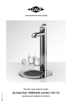
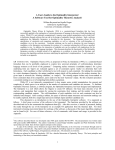
89585DE v1.20 06.14
Instant boiling water system
Zip HydroTap® MINIBOIL
Operating and installation instructions
Zip HydroTap® MINIBOIL
Contents
1. Safety Instructions
1. Safety Instructions . . . . . . . . . . . . . . . . . . . . . . . . . . . . . . . . . . . . . . . . . . . . . . . . . . . . . . . . . . . . . . . . . . . . . . . . . . . . . . . . . . . . . . . . 3
Installation, initial operation and maintenance of this appliance must only be carried out
by an authorised professional, who will then be responsible for adherence to applicable
standards and installation regulations. We assume no liability for any damage caused by
failure to observe these instructions.
2. Description of Appliance . . . . . . . . . . . . . . . . . . . . . . . . . . . . . . . . . . . . . . . . . . . . . . . . . . . . . . . . . . . . . . . . . . . . . . . . . . . . . . . . . . . 3
3. Technical Data . . . . . . . . . . . . . . . . . . . . . . . . . . . . . . . . . . . . . . . . . . . . . . . . . . . . . . . . . . . . . . . . . . . . . . . . . . . . . . . . . . . . . . . . . . . 4
Do not use the appliance until it has been correctly installed and unless it is in perfect
working order.
4. Installation . . . . . . . . . . . . . . . . . . . . . . . . . . . . . . . . . . . . . . . . . . . . . . . . . . . . . . . . . . . . . . . . . . . . . . . . . . . . . . . . . . . . . . . . . . . . . . 4
The appliance is designed for indoor use only. It must be protected from environmental
influences.
Installing the tap . . . . . . . . . . . . . . . . . . . . . . . . . . . . . . . . . . . . . . . . . . . . . . . . . . . . . . . . . . . . . . . . . . . . . . . . . . . . . . . . . . . . . . . . . 6
Small quantities of steam or boiling water may discharge through the tap at any time.
Ensure the tap is positioned so that this water falls into the sink and can drain way.
Installing the undersink unit . . . . . . . . . . . . . . . . . . . . . . . . . . . . . . . . . . . . . . . . . . . . . . . . . . . . . . . . . . . . . . . . . . . . . . . . . . . . . . . . . 6
The ambient temperature must be between 5° C and 35° C. Adequate ventilation must
be provided and the appliance must never be exposed to frost.
Optional: Installing the tray . . . . . . . . . . . . . . . . . . . . . . . . . . . . . . . . . . . . . . . . . . . . . . . . . . . . . . . . . . . . . . . . . . . . . . . . . . . . . . . . . 7
Switch off the power supply immediately if a fault occurs. In the event of a leak, shut
off the cold water supply immediately. Repairs must only be carried out by the customer
serviceor an authorised professional.
Optional: Installing an external ion exchanger . . . . . . . . . . . . . . . . . . . . . . . . . . . . . . . . . . . . . . . . . . . . . . . . . . . . . . . . . . . . . . . . . . . 7
This appliance can be used by children aged from 8 years and above and persons with
reduced physical, sensory or mental capabilities or lack of experience and knowledge if
they have been given supervision or instruction concerning use of the appliance in a safe
way and understand the hazards involved. Children shall not play with the appliance.
Cleaning and user maintenance shall not be made by children without supervision.
Commissioning . . . . . . . . . . . . . . . . . . . . . . . . . . . . . . . . . . . . . . . . . . . . . . . . . . . . . . . . . . . . . . . . . . . . . . . . . . . . . . . . . . . . . . . . . . . 7
5. Using the Tap . . . . . . . . . . . . . . . . . . . . . . . . . . . . . . . . . . . . . . . . . . . . . . . . . . . . . . . . . . . . . . . . . . . . . . . . . . . . . . . . . . . . . . . . . . . . 8
Child safety lock . . . . . . . . . . . . . . . . . . . . . . . . . . . . . . . . . . . . . . . . . . . . . . . . . . . . . . . . . . . . . . . . . . . . . . . . . . . . . . . . . . . . . . . . . . 8
Sleep mode. . . . . . . . . . . . . . . . . . . . . . . . . . . . . . . . . . . . . . . . . . . . . . . . . . . . . . . . . . . . . . . . . . . . . . . . . . . . . . . . . . . . . . . . . . . . . . 8
6. Cleaning and Maintenance . . . . . . . . . . . . . . . . . . . . . . . . . . . . . . . . . . . . . . . . . . . . . . . . . . . . . . . . . . . . . . . . . . . . . . . . . . . . . . . . . 9
Cleaning . . . . . . . . . . . . . . . . . . . . . . . . . . . . . . . . . . . . . . . . . . . . . . . . . . . . . . . . . . . . . . . . . . . . . . . . . . . . . . . . . . . . . . . . . . . . . . . . 9
Replacing the filter . . . . . . . . . . . . . . . . . . . . . . . . . . . . . . . . . . . . . . . . . . . . . . . . . . . . . . . . . . . . . . . . . . . . . . . . . . . . . . . . . . . . . . . . 9
Other maintenance. . . . . . . . . . . . . . . . . . . . . . . . . . . . . . . . . . . . . . . . . . . . . . . . . . . . . . . . . . . . . . . . . . . . . . . . . . . . . . . . . . . . . . . . 9
7. Troubleshooting . . . . . . . . . . . . . . . . . . . . . . . . . . . . . . . . . . . . . . . . . . . . . . . . . . . . . . . . . . . . . . . . . . . . . . . . . . . . . . . . . . . . . . . . . 10
8. Environment and Recycling . . . . . . . . . . . . . . . . . . . . . . . . . . . . . . . . . . . . . . . . . . . . . . . . . . . . . . . . . . . . . . . . . . . . . . . . . . . . . . . . 11
9. Notes . . . . . . . . . . . . . . . . . . . . . . . . . . . . . . . . . . . . . . . . . . . . . . . . . . . . . . . . . . . . . . . . . . . . . . . . . . . . . . . . . . . . . . . . . . . . . . . . . 12
2. Description of Appliance
The Zip HydroTap® MINIBOIL is an electronically controlled system for use in kitchens
and pantries. It provides filtered boiling water and filtered ambient drinking water. The
appliance itself is stowed away out of sight below the sink and the water is dispensed
via the tap (supplied). The tap can be positioned alongside the kitchen tap or separately
with a flat draining tray, as desired.
10. Quick Guide . . . . . . . . . . . . . . . . . . . . . . . . . . . . . . . . . . . . . . . . . . . . . . . . . . . . . . . . . . . . . . . . . . . . . . . . . . . . . . . . . . . . . . . . . . . 14
11. Warranty and Registration . . . . . . . . . . . . . . . . . . . . . . . . . . . . . . . . . . . . . . . . . . . . . . . . . . . . . . . . . . . . . . . . . . . . . . . . . . . . . . . . 15
2
3
Zip HydroTap® MINIBOIL
3. Technical Data
4. Installation
Model
The following regulation must be observed:
Zip HydroTap® MINIBOIL
Article number
• Installation must comply with all statutory regulations, as well as those of the local
electricity and water supply companies.
4100-44260
Rated voltage / rated power
230 V AC / 1.84 kW
Rated pressure
kPa / bar
Hot water temperature range °C
Hot water tank volume • The rating plate and technical specifications
70 – 700 / 0,7 – 7
92 – 98
litres
Before installation, ensure that:
1,8
Water connection
• There is enough space available for the undersink unit and the additional ventilation
(refer to installation drawing).
G ½"
Size (H × W × D)
cm
33,8 × 21,2 × 27,2
Weight (filled) kg
8,3
Ambient temperature °C
5 – 35
Protection class according to VDE
• A socket fitted with at least a 10A fuse is available within reach of the power cord
and the socket will still be accessible after the unit has been installed.
• A water supply connection at the rated pressure of the appliance with an isolating
valve is available within reach of the feed pipe. The isolating valve must still be
accessible after the unit has been installed.
Class I
Type of protection
IP 20
In addition to standard tools, the following special tools may be required:
• 35 mm diameter sheet metal hole punch for sink tops (not supplied)
4. Installation
• 35 mm diameter hole saw for timber worktops (not supplied)
• Pipe wrench (supplied) for fixing the tap
Handling the plastic hoses and push-fit connector (supplied):
• If shortening the hoses be sure to make a clean cut straight across the hose, using a
sharp blade. Never pinch off the hose with a blunt instrument.
Dia. 46
• The hoses must not be under tension when installed. The minimum bending radius is
25 mm. If there is a kink in the hose, there is a risk of leakage at the kink.
125
208
Dimensions in mm
Min. distance
200
Insertion:
• Push the hose into the quick-release connector as far as it will go (approx. 15 mm) to
ensure a tight connection.
Removal:
Press collet
Pull
tube
338
Push fully in
Depth 269
Min. distance 50
Min. distance 50
212
4
5
Zip HydroTap® MINIBOIL
4. Installation
4. Installation
Installing the tap
Tap
Spacer
Threaded rod
Tap
Note: The tap must not be installed more than 900 mm above the base of the
undersink unit. Failure to do this may result in poor water delivery.
Spacer
Note: Under no circumstances should the tap be twisted after the installation is
complete.
Threaded rod
Spacer
1. Make sure that the tap location will allow water from the tap to fall into a sink or
other basin fitted with a drain to drain away.
Spider clamp
Fixing nut
S/S washer
4. Pass the hoses down through the 35 mm hole in the worktop/sink and locate the tap
head on its mounting location.
Spider clamp
Fixing nut
Cut a 10 mm slot for
the bolt
35 mm hole
for tap
Installing the undersink unit
Note: An air gap of at least 50 mm at the left and right of the unit must
be provided for adequate ventilation. If the unit is to be operated inside a
cupboard, the silicon buffers supplied should be affixed to the inside edge of
the cupboard doors. The 4 mm air gap thus created provides a minimum fresh
air supply.
Note: Additional ventilation must be ensured if the temperature in the base
unit exceeds 35°C.
Fastening
bolt
Drain
pipe bend
Hole needed for tray
recess 108 mm
View from below
3. Mount the bracket for the external filter in an accessible position near the water
connection and install the filter in the bracket.
Cold
water
Signal
lead
Power
lead
5. Install the tap as described from point 3 onwards of ‘Installing the tap’.
6. If the drain bend is facing the wrong way, slacken off the fastening nut above the
bend, turn it to the correct position and then tighten up the fastening nut again.
7. Connect the drain bend to a siphon connecting sleeve, using a 22 mm diameter hose.
If no siphon connecting sleeve is available, use the snap connecting sleeve.
a. Place the snap connecting sleeve on the side of the siphon facing the sink. Drill a
13 mm diameter hole in the drain pipe behind the snap connecting sleeve for a
drain connection. Use a suitable sealant to make a watertight seal between the
snap connecting sleeve and the drain pipe.
An additional ion exchanger can be used to prevent limescale deposits in the undersink
unit and thus extend the maintenance intervals.
Note: If installing an external ion exchanger, follow the instructions supplied for
the filter head and filter cartridge.
1. Install the filter head of the ion exchanger so that it can be connected to the pressure
limiter at the isolating valve and to the filter head inlet of the regular filter.
2. Connect the pressure limiter on the isolating valve with the external ion exchanger
and connect the ion exchanger with the external filter. Use the existing hoses and the
hoses supplied and note the flow direction (arrows marked on the filter heads).
2. Fit the pressure limiting valve to the isolating valve (not supplied)
Boiling
Steam water
2. Place the template supplied over the tray installation location.
Optional: Installing an external ion exchanger
1. Position the undersink unit as close to the tap as possible.
Inlet
1. Ensure that a water supply, a drain, a socket fitted with at least a 10 A fuse and
enough room for the undersink unit are all available at the tray installation location.
4. Insert the tray. Place the plastic spacer between the worktop and the tray at the
35 mm hole. Working from below, fasten the tray to the threaded rod using the
washer and nut supplied.
3. Push the black spacer on to the tap from underneath and ensure it remains in
position. A light smearing of silicon sealant on the underside of the spacer will ensure
a watertight fit.
5. From the underside, push the stainless steel washer over the hoses and then push the
spider clamp on to the threaded rod of the tap fitting. Secure the spider clamp with
the fastening nut. Check the tap head is in the correct position before tightening up
the nut.
The tray (article number: 44101) is an accessory which can be used to install the tap
independently of a kitchen sink.
3. Cut out the holes as indicated on the template.
2. Cut a 35 mm diameter hole in the worktop/sink at the place where the tap is to be
installed.
S/S washer
Optional: Installing the tray
4. Connect up the pressure limiting valve to the filter bracket and connect the filter
bracket to the water inlet of the undersink unit. Note the flow direction marks on the
filter bracket. Use the flexible hoses supplied to make these connections.
Commissioning
1. Before using the tap unit for the first time, flush through the connecting pipes and
the filter thoroughly. To flush, detach the hose from the water inlet of the undersink
unit and hold it over a drain or bucket. Turn on the water and allow it to run for
about three minutes. Then reattach the hose to the water inlet of the undersink unit
and check the installation for leaks.
5. Connect the tap hoses to the undersink unit. Ensure there is a continuous fall from
the tap down to the undersink unit. Trim the hoses to avoid loops and kinks. The
hoses must not be lengthened. Use the spring clamps supplied to fasten the hoses in
place.
a. Connect the red marked silicon hose to the boiling water connection.
2. If no leaks occur plug the plug into the socket to activate the unit.
b. Connect the unmarked silicon hose to the steam connection.
3. The unit is now in normal operating mode. Wait for the LED to show a steady light,
and then check the water flow and the temperature.
c. Connect the cold water connection on the unit to the push-fit connector on the
tap. Use the blue plastic hose, trimming it to length as necessary.
Operation
4. Connect the signal leads of the tap and the undersink unit. Attach the plug
connection at a location away from any water splashes.
Note: If the Zip HydroTap® MINIBOIL has not been used for several days, allow
the tap to run ambient water for about one minute.
Filter head article number: 84506
Filter candle article number: 84500
Press the red lever to dispense boiling water. Pull the lever up to dispense boiling water
continually. The water will flow for about 15 seconds. Then manually return the lever to
the off position.
Press the blue lever to dispense ambient water. Pull the lever up to dispense ambient
water continually. The water will flow for about 15 seconds. Then manually return the
lever to the off position.
6
7
Zip HydroTap® MINIBOIL
5. Using the Tap
Red LED: boiling water
• Steady light: boiling water is ready and can be dispensed.
• Flashing: the water temperature is below the set value. Boiling water cannot be
dispensed.
Dispense
boiling water
Dispense
cold water
• Flashing slowly: the unit is in Sleep mode.
White LED: filter
• Flashing: the filter needs to be replaced. This LED will start flashing either after 12
months of use or after 4,000 litres of water have been filtered, whichever is earlier.
Both LEDs: fault
• Flashing: there is a fault in the unit. In that case, switch off the unit for at least
15 minutes. If the fault has not been corrected when the unit is switched on again,
contact customer service.
Child safety lock
A child safety lock can be enabled to prevent boiling water flowing out of the tap if the
boiling water control is accidentally operated. To draw boiling water when the child
safety lock is enabled, the Safety button has to be pressed and held down at the same
time as the red lever.
To enable the child safety lock, press the Safety button and the blue lever at the same
time and hold for about ten seconds. The LED on the Safety button flashes when the
child safety lock is enabled.
To disable the child safety lock, press the Safety button and the blue lever at the same
time and hold for about ten seconds. The LED on the Safety button stops flashing when
the child safety lock is disabled.
Sleep mode
The unit can be set to Sleep mode to save energy. If Sleep mode is enabled, the unit
will switch to Sleep if it has not been used for two hours. The water temperature will be
maintained at 64°C. Operation of the tap during this time will wake the system from
sleep and the water will start heating up again. Boiling water is available as soon as the
red LED shows a steady light.
Press the Safety button three times in succession to enable or disable Sleep mode.
The red LED and the blue LED will flash simultaneously to confirm that Sleep is enabled.
They will flash alternately to confirm that Sleep is disabled.
Child safety lock
8
Zip HydroTap® MINIBOIL
Installation template for the tray
Ø 219 mm
Installation template for the tray
Ø 35 mm
+ +0,5
mm
Diametre
35 mm
0.5 mm
Hole
for für
tap connecting
hoses
Loch
die Armatur-Anschlussschläuche
73
Diametre 219 mm
Außendurchmesser
Outside diameter of tray
des Tableaus
Scale: 1:3,3
60
21
Maßstab: 1:3,3
Ø 108 mm
Diametre
108für
mmdie
Öffnung
Hole for tray recess
Tableauvertiefung
Ø 10 mm
Diametre
10 mm
10 mm-Aussparung
für
10 mm hole for fastening bolt
den Befestigungsbolzen
Scale: 1:1
Maßstab 1:1
Zip HydroTap® MINIBOIL
6. Cleaning and Maintenance
Cleaning
The plastic surfaces and taps should only be wiped with a damp cloth. Do not use
abrasive or chlorine-based cleaning agents or solvents.
Do not clean the undersink unit and tap with a water jet, as that could damage the
electronic components.
Replacing the filter
The white LED on the tap will flash either after the filter has been in use for 12 months
or after 4,000 litres of water have been filtered, indicating that the filter needs to be
replaced. How often the filter needs to be replaced depends on the local water quality
and may range from 1,000 to 10,000 litres. The filter may have to be replaced earlier
if an unpleasant odour or taste occurs.
Water may drip out of the filter holder during replacement. Have a bucket and cloths
ready to mop up any water that escapes.
1. Close the isolating valve to shut off the water supply.
2. Turn the filter cartridge one quarter turn anticlockwise, as far as it will go.
3. Carefully pull the filter cartridge out of the filter holder from below. Hold the cartridge
level to avoid spilling dirty water.
4. Unpack the new filter cartridge and write today’s date in the space provided at
the label. Avoid contact with the O-rings and filter opening, as that could result in
bacterial contamination of the filter.
5. Push a new replacement filter cartridge into the filter holder and turn it clockwise as
far as it will go to lock it in position.
6. To flush the filter, detach the hose from the water inlet of the undersink unit and
hold it over a drain or bucket. Open the isolating valve and allow the water to run for
several minutes.
7. Then close the isolating valve and reattach the hose to the water inlet of the
undersink unit.
8. Open the isolating valve to re-establish the water flow to the unit.
9. Press the red and the blue levers on the tap simultaneously and hold for 10 seconds
to reset the filter replacement indicator. The white LED will remain lit for the
10 seconds before going out again.
10. Dispose of the used filter correctly.
Other maintenance
Regular servicing is needed to keep the unit working efficiently at all times. Please
contact customer service for more information about the servicing of your unit.
9
Zip HydroTap® MINIBOIL
7. Troubleshooting
8. Environment and Recycling
If a problem occurs with your Zip HydroTap® unit, the cause is often something very simple. Try to resolve the problem yourself with the
aid of the table below. That will help you avoid the expense of an unnecessary call-out.
Problem
No LED display and
no water when tap is
operated.
Cause
Remedy
No power.
Check power supply.
Tap is not connected to undersink unit.
Check plug connection between tap and
undersink unit.
Possible internal fault.
Contact customer service.
No water flow when tap is
operated.
No water.
Check water supply.
Tap is not connected to the undersink unit.
Check hoses between tap and undersink unit.
Water is not at boiling temperature.
Wait for water to reach boiling temperature.
Unit is slow to refill after
drawing water.
Filter blocked.
Check whether the white LED is flashing,
indicating that the filter needs to be replaced.
Unit is in Sleep mode.
Press red lever and wait for red LED to show a
steady light.
Water not hot.
All LEDs are flashing.
Possible internal fault.
Contact customer service.
Power interruption.
Switch off unit, wait 15 minutes and then
switch on again.
Water interruption.
Check water inlet for blockages.
Possible internal fault.
Contact customer service.
Your product was manufactured from high-quality, reusable materials and components. Please respect in case of
discarding that electrical devices should be disposed of separately from household waste at the end of their service life. Therefore, please take this device to a municipal collection point that accepts electronic scrap on a free
of charge basis. Disposing it correctly will support environmental protection and will prevent any potential negative effects on human beings and the environment that could arise from inappropriate handling of these devices
at the end of their service life. Please contact your local authority for further details of your nearest designated
collection point or recycling site.
Business customers: If you wish to discard electronic equipment, please contact your dealer or supplier for further information.
If you cannot rectify the fault with the aid of this table, please contact:
CLAGE GmbH
Central Customer Service
Pirolweg 8
21337 Lüneburg
Germany
Tel.: +49 4131 - 89 01-40
Fax: +49 4131 - 89 01-41
E-mail: service @ clage.de
Internet:www.clage.de
10
11
Zip HydroTap® MINIBOIL
9. Notes
9. Notes
12
13
Zip HydroTap® MINIBOIL
10. Quick Guide
11. Warranty and Registration
This is a precision unit made from the best available material. It can be expected to function for
many years without any problems.
For boiling water:
Press the red lever and the Safety button
at the same time.
For cold water:
Press the blue lever.
No warranty applies to the life of a filter cartridge installed with the unit, as the life of the
cartridge depends on the water quality and water consumption rate.
These warranty conditions apply only to our units purchased and used in the Federal Republic of
Germany.
For other countries, the warranty stipulated in the terms of sale and delivery or according to the
statutory warranty provisions of the country concerned applies. This warranty does not affect the
customer’s statutory warranty rights (performance, cancellation, compensation and reduction of
the purchase price). We provide this warranty voluntarily as the manufacturer.
Our warranty period is 24 months from the date of purchase on a water heating appliance for
home use and 12 months in the case of commercial/industrial use. No claims under the warranty
will be considered unless the warranty certificate supplied with the unit has been duly and
completely filled in. The warranty certificate must be produced along with the purchase receipt
if making a claim under the warranty. We suggest you send us the warranty certificate for
registration after your unit has been installed.
Boiling water will be dispensed
No claims under the warranty will be considered in the case of damage or malfunction due
to limescale, chemical or electrochemical agents, incorrect use, incorrect connection, fouling
up of the water inlet or outlet fittings, failure to follow the installation, maintenance and use
instructions, unauthorised modifications to the unit or use of spare parts not originating from the
manufacturer.
Cold water will be dispensed
Natural wear and tear of the unit is likewise not covered by the warranty.
Any damage / defects occurring must be notified to us in writing within 14 days of becoming
apparent. We will then consider whether a claim under the warranty is valid in law. If so, we will
decide how the damage / defect is to be remedied, i.e. by an authorised service contractor or by
our own Service department.
The Zip and HydroTap names are registered trademarks of Zip Heaters (Aust) Pty Ltd. Zip products
described in this publication are manufactured under one or more of the following patents:
AU675601, AU637412, AU635979, GB0422305, GB2065848, US4354049, US5103859 and
US5099825. Other patents are in force and other patent applications are pending.
✂
Registration and Warranty Certificate
Please register your unit online at www.clage.de as soon as it has been installed
If this is not possible, please fill in the registration slip below and fax or post it back to Central Customer Service. Registering your unit
can make it easier to establish the date of installation if work ever has to be done on the unit under the warranty.
Unit Data
Model:
Art. No.:
Serial No.
Date of purchase
Purchased from:
(refer to receipt)
User
Name:
Tel.:
Address:
E-mail:
Postcode:
Installer
Company:
Tel.:
(or dealer)
Address:
Fax:
Postcode:
Application
14
Town/city:
☐ Home
Town/city:
E-mail:
☐ Business
15
CLAGE GmbH
Pirolweg 1–5
21337 Lüneburg
Germany
Telefon: +49 (0) 4131 · 89 01- 0
Telefax: +49 (0) 4131 · 83 200
Subject to change 9120-9193 06.14 Zip
E-Mail:[email protected]
Internet:www.clage.de
✂
We want to know what you think.
We would like to know what you think of the quality of this product,
ease of use, user manual, etc.
CLAGE GmbH
Central Customer Service
Pirolweg 1-5
21337 Lüneburg
Germany