1
Pelican
1
G3
G4
935
425
425
2170
840
473
473
1170
6
935
390
840
553
1170
2
920
2060
345
840
935
390
345
935
840
400
390
1030
2170
400
553
390
2060
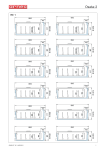
ILLUSTRAZIONI
ILLUSTRATIONS
ABBILDUNGEN
ILLUSTRATIONS
ILLUSTRACIONES
400
920
400
750
750
1030
750
750
1170
1170
750
10 8
ARNEG S.p.A.
VIA VENEZIA 58 - CAMPO SAN MARTINO - PADOVA - ITALY
Tel. +39 049 9699333 Fax +39 049 9699444 - [email protected]
1
2
Hz
SUPERF.ESP.
DISPLAY AREA
W
ILLUMINAZIONE
LIGHTING
W IP
MASSA
WEIGHT
kg
13
A
400
m
2
REFRIGERANTE
REFRIGERANT
CLASSE
CLASS
ORDINE
W.ORD.
17
ANNO
YEAR
18
425
SBRINAMENTO
DEFROSTING
4
7
15
W
840
913
COMMESSA
W.SCHED
V
920
16
MATRICOLA
S/N
390
CODICE
ITEM
2060
3
5
9
11
12
14
3
Rif. 1
Rif. 2
Max 25mm
05060104 00 13/01/2010
1
Pelican
4
er
30cm
wa
5
t
CHEMICALS
Rif. 7
Rif. 6
Rif. 3
Rif. 4
L
A
N
Prg
IO
T
P
aux
Rif. 5
Rif.12
O
mute
aux
Set
def
Rif.10
Rif. 9
HACCP
Rif. 8
Rif.11
Rif.13
A
D
B
C
A
A
B
2
05060104 00 13/01/2010
Pelican
CAUTION!!
er
6
wa
t
CHEMICALS
7
8
A
ȅȀ
05060104 00 13/01/2010
B
NO
3
Pelican
200
HO
2
850
H2O
200
538
300
H2O
HO
2
200
1250
1875
HO
2
H2O
200
300
H2O
203
203
R404
937,5
937,5
2500
850
300
H2O
203
203
1250
200
200
R404
203
R404
H2O
203
9
1875
1875
3750
10
4
05060104 00 13/01/2010
Pelican
11
4
2
1
10
7
8
4
5
6
11
12
4 5 6
1
3 4
1
1
1
7 9
05060104 00 13/01/2010
5
Pelican
12
315
B
D
C
D
30
230
170
500
C
B
50
A
500
A
C
90
B
A
500
Β C
105
230
B
Α
A-C
A = Sonda aspirazione aria
B = Sonda fine sbrinamento
C = Sonda aria mandata
D = Termostato sicurezza cavi caldi porte
A = Air IN probe
B = End-defrost probe
C = Air OUT probe
D = Door heating cables safety thermostat
Sonda di temperatura / Temperature probe Sacet/CAREL L=4000 cod.04510153
6
05060104 00 13/01/2010
7
POWER 1
+
S
+=ALIM./SUPPLY
S=SEGNALE/SIGNAL
TELAIO
9
8
R
+ -
1
1
S
M
M
INTERR.LUCI
LIGHT SWITCH
PE 5A 5B
M
PE 5A 5B
ALIMENTAZIONE VENTIL. EVAP.
EVAPORATOR FANS SYPPLY
2
+=ALIM./SUPPLY
-=COMUNE/COMMON
S=SEGNALE/SIGNAL
PE
PE
PE
ALIMENTAZIONE VALVOLA
VALVE SUPPLY
2
PE N
PE N
TRASDUTTORE RAZIOMETRICO
RATIOMETRIC TRANSDUCER
N
N 1A N 1A N 1B 30 31
7
N
N 1A N 1A N 1B 30 31
mA
I
TRASDUTTORE DI PRESSIONE 4-20 mA
PRESSURE TRANSDUCER 4-20 mA
I
PE N
C.CALDO MONTANTE CORNICE
FRONT FRAME HEATER
PE N
C.CALDO PERIM.CORNICE
PERIM.FRONT FRAME HEATER
ALIMENTAZIONE CAVI CALDI
HEATERS SUPPLY
POWER 2
VENTILATORI EVAPORATORE
EVAPORATOR FANS
VALVOLA SOLENOIDE
SOLENOID VALVE
EEV
POWER 3
R2
R1
1
PE
PE
PE
2
3
4
R3
PE N R1 PE N R2 PE N R3
RESISTENZA SBRINAMENTO
DEFROST HEATER
PE N R1 PE N R2 PE N R3
RESISTENZA SBRINAMENTO
DEFROST HEATER
ALIMENTAZIONE RESIST. SBRIN.
DEFROST HEATER SUPPLY
01
02
RESISTENZA SBRINAMENTO
DEFROST HEATER
POWER 4
3
2
1
4
1
4
2
1
3
2
CON CAVO COLORATO:
BLU(1)-MARRONE(2)-GRIGIO(3)-NERO(4)
3
WITH COLORED CABLE
BLUE(1)-BROWN(2)-GRAY(3)-BLACK(4)
4
5
POWER 5
I
I
2
PE N
PE N
1
UPPER LIGHTING CABLE
2
4
1
3
2
3
2
4
Sout
SONDA MANDATA ARIA
AIR OUTLET PROBE
2
1
PROBES 1
Sdef
SONDA FINE SBRINAM.
END DEFROST PROBE
1
CAVO DI COLLEGAMENTO
ILLUMINAZIONE VASCA
Sin
SONDA RIPRESA ARIA
AIR INLET PROBE
1
TANK LIGHTING CABLE
ALIMENTAZIONE ILLUMIN.
LIGHTING SUPPLY
5
G.VERDE/Y.GREEN
1 BLU/BLUE
2 MARRONE/BROWN
CAVO DI COLLEGAMENTO
ILLUMINAZIONE SUPERIORE
CAVO DI COLLEGAMENTO
ILLUMINAZIONE CORRIMANO
RAIL LIGHTING CABLE
Ssh
SONDA SURRISCALDAMENTO
SUPERHEATING PROBE
6
6
5
5
PROBES 2
1
1
2
2
2
3
4
5
S
5
5
SCHEMA ILLUMINAZIONE COMBINATI BT: D5A15927
WIRING DIAGRAM OF LIGHTING FOR COMBINED LT: D5A15927
R
4
3
+ -
4
3
Ssh
SONDA SURRISCALDAMENTO
SUPERHEATING PROBE
TRASDUTTORE DI PRESSIONE
PRESSURE TRANSDUCER
1
Sev
SONDA INGRESSO REFRIGERANTE
REFRIGERANT INLET PROBE
L
N
1
2
NON UTILIZZATI
NOT USED
5
6
SCHEMA ELETTRICO SOVRASTRUTTURA SOLO MORSETTIERA/ ONLY TERMINAL BLOCK ELECTRIC PANEL FOR SUPERSTRUCTURE
MESSA A TERRA DEL TELAIO
CHASSIS EARTHING
ILLLUMINAZIONE PORTE
DOORS LIGHTING
CAVI CALDI VETRATE
GLASS DOOR HEATERS
TERMOSTATO VETRATE
GLASS DOOR THERMOSTAT
C.CALDO LAMIERA VASCA
TANK PLATE HEATER
05060104 00 13/01/2010
13
Pelican
05060104 00 13/01/2010
PE PE
INTERR.LUCI
LIGHT SWITCH
POWER 1
PE PE
2
3
N
1
N
1
N
1
N
+
mA
1
N
S
1
N
ALIMENTAZIONE CAVI CALDI
HEATERS SUPPLY
+=ALIM. /SUPPLY
S=SEGNALE /SIGNAL
+
R
S
+=ALIM. /SUPPLY
-=COMUNE /COMMON
S=SEGNALE /SIGNAL
R3
N
R2 PE
PE
N
R2 PE
TR ASDUT TORE R A ZIOME TRICO
R ATIOME TRIC TR ANSDUCER
N
R1 PE
PE
N
R1 PE
R2
N
N
R1
PE
PE
ALIMENTAZIONE RESIST. SBRIN.
DEFROST HEATER SUPPLY
R4
R4
R4
N
R3 PE
PE
N
R3 PE
COLLEGAMENTO ILLUMINAZIONE/LIGHTING CONNECTION
ALIMENTAZIONE VENTIL. EVAP.
EVAPORATOR FANS SYPPLY
ALIMENTAZIONE VALVOLA
VALVE SUPPLY
PE
I CONNE T TORI POWER 4 E POWER 5 NON SONO UTILIZ Z ATI NEL CASO
DI ISOLE SENZ A ILLUMINA ZIONE E VASCHE COMBINATI BT 2E.
POWER 4 AND POWER 5 CONNECTORS ARE NOT USED IN CASE OF
ISL ANDS WITHOUT LIGHTING AND TANK OF COMBINED LT 2E.
PE 5A 5B
2
CONNECTION FOR CABINET WITH 2 E V. (MALMOE3)
PE 5A 5B
2
CONNECT R1 E VAPOR ATOR 1 PAR ALLEL R1 E VAPOR ATOR 2.
SIMIL ARLY FOR THE OTHER HE ATERS (R2 AND R3).
N
PE
M
N
PE
COLLEGAMENTO PER BANCHI A 2 E V. (MALMOE3)
1
N
COLLEGARE L A R1 DELL'E VAPOR ATORE 1 IN PAR ALLELO
CON L A RESISTENZ A R1 DELL'E VAPOR ATORE 2. ANALOGAMENTE
PER LE ALTRE RESISTENZE (R2 E R3).
1
N
TR ASDUT TORE DI PRESSIONE 4-20 mA
PRESSURE TR ANSDUCER 4-20 mA
4
1
1
VALVOLA SOLENOIDE
SOLENOID VALVE
RESISTENZA SBRINAMENTO
DEFROST HEATER
3
2
4
3
1
4
3
2
2
1
1
CON CAVO COLORATO:
BLU(1)-MARRONE(2)-GRIGIO(3)-NERO(4)
ALIMENTAZIONE ILLUMIN.
LIGHTING SUPPLY
4
5
5
01
02
PE
PE
1
N
N
2
I
I
1
PROBES 1
2
2
2
1
Sout
4
4
3
3
Sdef
6
5
SCHEMA ILLUMINA ZIONE ISOLE BT: D5A15925
WIRING DIAGR AM OF LIGHTING FOR ISL ANDS LT: D5A15925
6
5
Sin
SONDA RIPRESA ARIA
AIR INLET PROBE
1
LIGHTING RAIL/
LIGHTING AIR OUTLET CABLE
1
1
1
2
2
2
4
5
-
+
3
5
4
3
S
5
4
3
Ssh
SONDA SURRISCALDAMENTO
SUPERHEATING PROBE
TRASDUTTORE DI PRESSIONE
PRESSURE TRANSDUCER
L
N
1
2
SCHEMA ELET TRICO SOLO MORSET TIERA VASCA STANDARD / ONLY TERMINAL BLOCK ELECTRIC PANEL FOR BASIN
MESSA A TERRA PER CAVI CALDI A
SINGOLO ISOLAMENTO
EARTH CONNECTION FOR SINGLE
INSULATED HEATERS
CAVO CALDO SUPERIORE VETRATA
UPPER GLASS HEATER
CAVO CALDO INFERIORE VETRATA
LOWER GLASS HEATER
CAVO CALDO SPALLA/ASPIRAZIONE
SIDE WALL/AIR SUCTION HEATER
CAVO CALDO NASETTO DI MANDATA
AIRFLOW HEAD HEATER
POWER 2
VENTILATORI EVAPORATORE
EVAPORATOR FANS
EEV
POWER 3
RESISTENZA SBRINAMENTO
DEFROST HEATER
RESISTENZA SBRINAMENTO
DEFROST HEATER
RESISTENZA SBRINAMENTO
DEFROST HEATER
POWER 4
WITH COLORED CABLE
BLUE(1)-BROWN(2)-GRAY(3)-BLACK(4)
POWER 5
CAVO DI COLLEGAMENTO
SOVRASTRUTTURA ILLUMINATA
UPPER LIGHTING CABLE
CAVO DI COLLEGAMENTO
CORRIMANO/MANDATA
SONDA MANDATA ARIA
AIR OUTLET PROBE
G.VERDE/Y.GREEN
1 BLU/BLUE
SONDA FINE SBRINAM.
2 MARRONE/BROWN END DEFROST PROBE
Ssh
SONDA SURRISCALDAMENTO
SUPERHEATING PROBE
PROBES 2
Sev
SONDA INGRESSO REFRIGERANTE
REFRIGERANT INLET PROBE
NON UTILIZZATI
NOT USED
8
5
6
14
Pelican
05060104 00 13/01/2010
21
22
26
27
21
22
23
24
N
L
N
L
RAIL LIGHTING CABLE
CAVO DI COLLEGAMENTO
ILLUMINAZIONE CORRIMANO
TANK LIGHTING CABLE
CAVO DI COLLEGAMENTO
ILLUMINAZIONE VASCA
LAMPADE T5
OSRAM QTP5 1x
LAMPADE T8
OSRAM QTP8 1x
IL TELAIO PORTE E' FORNITO CON GLI
ALIMENTATORI GIA' COLLEGATI ALLE
RELATIVE LAMPADE.
THE DOOR FRAME IS SUPPLIED WITH
BALLASTS ALREADY CONNECTED TO THE
LAMPS.
ILLUMINAZIONE CORRIMANO (OPTIONAL)
RAIL LIGHTING (OPTIONAL)
ILLUMINAZIONE VASCA
TANK LIGHTING
ILLUMINAZIONE SUPERIORE (OPTIONAL)
UPPER LIGHTING (OPTIONAL)
21
22
23
24
25
26
27
LAMPADE T5/T8
OSRAM QTP5/8 2x
PE
N
L
PE
N
L
1
2
CAVO DI COLLEGAMENTO
ILLUMINAZIONE SUPERIORE
UPPER LIGHTING CABLE
Pelican
15
9
10
4x16
494,6
1600
2x22
130,1
1425
1950
169,8
2x22
593
2140
656,2
4x16
743
3000
246,1
3x22
889
9,07
6x16
1114
3250
980,6
3750
sportelli
doors
1710
243,3
2x22
653
905
649,2
2x16
1425
130,1
2x22
TISE-SW
29 bar
R404A
444
1600
530,6
4x16
1950
169,8
2x22
593
2140
704,2
4x16
825
3000
246,1
3x22
889
6x16
1238
3250
1050,6
9,07
6,05
4,53
619
3750
2500
-18°C / -25°C
557
sportelli
doors
06257209
vasca
basin
G3 H216
sportelli
doors
1875
vasca
basin
06257206
sportelli
doors
06257204
vasca
basin
Max + 32°C / Min - 35°C
TST
06256481
vasca
basin
< 60
sportelli/doors: 2x45’
vasca/basin: 3x45’
sportelli
doors
1710
243,3
2x22
653
TST
905
691,2
2x16
619
06257281
vasca
basin
Automatico/Elettrico - Automatic/Electrical - Automatisch/Elektrisch - Automatique/Electrique - Automático/Eléctrico - Ⱥɜɬɨɦɚɬɢɱɟɫɤɢɟɗɥɟɤɬɪɢɱɟɫɤɨɟ
557
6,05
4,53
444
2500
sportelli
doors
06256409
vasca
basin
G3 H205
sportelli
doors
1875
vasca
basin
06256406
sportelli
doors
06256404
vasca
basin
Dati tecnici
Technical data
Technische Daten
Données techniques
Datos Técnicos
Contenuto modificabile senza preavviso, Content that could be change without notice, Inhalt Veränderbar ohne Vorankündigung, Contenu modifiable sans préavis, Contenido modificable sin previo aviso, ɋɨɞɟɪɠɚɧɢɟɢɡɦɟɧɹɟɬɫɹɛɟɡɩɪɟɞɭɩɪɟɠɞɟɧɢɹ
Codice, Code, Kode nr., Code, Código, Ʉɨɞ
Lunghezza senza spalle, Length without ends, Länge ohne Seiten,
mm
Longeur sans joues, Longitud sin laterales, Ⱦɥɢɧɚɛɟɡɛɨɤɨɜɢɧ
Temp. di esercizio, Working temperature, Betriebstemperatur,
°C
Temp. de fonctionnement, Temperatura de trabajo, Ɋɚɛɨɱɚɹɬɟɦɩɟɪɚɬɭɪɚ
Temperature ammissibili, Allowed temperature, Zulässige Temperaturen
°C
Températures admissibles, Temperaturas admitidas, Ⱦɨɩɭɫɬɢɦɵɟɬɟɦɩɟɪɚɬɭɪɵ
- (Ts) 97/23 CE Superficie di esposizione orizzontale totale, Total horizontal display surface,
m2
Gesamte Ausstellefläche, Surface d’exposition horizontale total , Superficie de
exposición de apoyo total, Ƚɨɪɢɡɨɧɬɚɥɶɧɚɹɩɥɨɳɚɞɶɷɤɫɩɨɡɢɰɢɢ
Volume netto, Net volume, Netto inhalt, Volume net, Volumen neto,
dm 3
ɑɢɫɬɵɣɜɟɫ
Potenza frigorifera, Refrigeration Power, Kühlleistung, Puissance frigorifique
W
Potencia frigorígena, ɏɨɥɨɞɢɥɶɧɚɹɦɨɳɧɨɫɬɶ
Refrigerante, Refrigerant, Kühlmittel, Réfrigérant, Refrigerante, ɏɥɚɞɚɝɟɧɬ
Massima pressione ammissibile, Max allowed pressure, Maximal zulässiger
bar
Druck, Pression maximale admissible, Máxima presión admitida, Ɇɚɤɫɢɦɚɥɶɧɨ
ɞɨɩɭɫɬɢɦɨɟ Ⱦɚɜɥɟɧɢɟ- (Ps) 97/23 CE Valvola espansione, Expansion Valve, Expansion-Ventil, Valve d’expansion, Válvula
de expansión, Ɋɚɫɲɢɪɢɬɟɥɶɧɵɣɤɥɚɩɚɧ
n° x W
Ventilatori, Fans, Gebläse, Ventilateurs, Ventiladores, ȼɟɧɬɢɥɹɬɨɪɵ
Cavi caldi anticondensa, Anti-condensation hot cables,
Kondenswasserschutzwarmkabel, Câble chauffant anti-condensation, Resistencias
W
anticongelamiento, ɇɚɝɪɟɜɚɬɟɥɶɧɵɟɤɚɛɟɥɢɩɪɞɨɬɜɪɚɳɚɸɳɢɟɨɛɪɚɡɨɜɚɧɢɟ
ɤɨɧɞɟɧɫɚɬɚ
Resistenza di sbrinamento, Defrost heater, Abtauwiderstand,Resistance de
W
dégivrage,Resistencias de descongelation, Ɇɨɳɧɨɫɬɶɨɬɬɚɢɜɚɧɢɹ
Tipo di sbrinamento, Defrosting type, Abtautyp, Type de dégivrage, Tipo
descongelation, Ɍɢɩɨɬɬɚɢɜɚɧɢɹ
Sbrinamenti consigliati, Recommended Defrosting, Empfohlene Abtauungen,
n°/24h
Dégivrages conseillés, Descongelaciones aconsejadas, Ɋɟɤɨɦɟɧɞɭɟɦɵɟ
ɨɬɬɚɢɜɚɧɢɹ
Livello di rumorosità , Noise level, Schallpegel, Niveau de bruit, Nivel de ruido,
db (A)
ɍɪɨɜɟɧɶɲɭɦɚ
Modello, Model, Modell, Modele, Modelo, Ɇɨɞɟɥɶ
.
.
.
.
.
.
Pelican
Dati Tecnici, Technical Data, Technische Daten, Données techniques, Datos Técnicos, 05060104 00 13/01/2010
05060104 00 13/01/2010
4x16
494,6
1600
2x22
130,1
1425
1950
169,8
2x22
618
2140
656,2
4x16
743
3000
246,1
3x22
926
9,07
6x16
1114
3250
980,6
3750
sportelli
doors
1710
243,3
2x22
679
sportelli
doors
-18°C / -25°C
463
905
649,2
2x16
1425
130,1
2x22
TISE-SW
29 bar
R404A
557
4,53
4x16
619
1600
530,6
1875
06257604
vasca
basin
Max + 32°C / Min - 35°C
TST
06256881
vasca
basin
1950
169,8
2x22
618
6,05
4x16
825
2140
704,2
2500
sportelli
doors
3000
246,1
3x22
926
6x16
1238
3250
1050,6
9,07
3750
06257609
vasca
basin
G4 H216
sportelli
doors
06257606
vasca
basin
< 60
sportelli/doors: 2x45’
vasca/basin: 3x45’
sportelli
doors
1710
243,3
2x22
679
TST
905
691,2
2x16
619
06257681
vasca
basin
Automatico/Elettrico - Automatic/Electrical - Automatisch/Elektrisch - Automatique/Electrique - Automático/Eléctrico - Ⱥɜɬɨɦɚɬɢɱɟɫɤɢɟɗɥɟɤɬɪɢɱɟɫɤɨɟ
557
6,05
4,53
463
2500
sportelli
doors
06256809
vasca
basin
G4 H205
sportelli
doors
1875
vasca
basin
06256806
sportelli
doors
06256804
vasca
basin
Contenuto modificabile senza preavviso, Content that could be change without notice, Inhalt Veränderbar ohne Vorankündigung, Contenu modifiable sans préavis, Contenido modificable sin previo aviso, ɋɨɞɟɪɠɚɧɢɟɢɡɦɟɧɹɟɬɫɹɛɟɡɩɪɟɞɭɩɪɟɠɞɟɧɢɹ
Codice, Code, Kode nr., Code, Código, Ʉɨɞ
Lunghezza senza spalle, Length without ends, Länge ohne Seiten,
mm
Longeur sans joues, Longitud sin laterales, Ⱦɥɢɧɚɛɟɡɛɨɤɨɜɢɧ
Temp. di esercizio, Working temperature, Betriebstemperatur,
°C
Temp. de fonctionnement, Temperatura de trabajo, Ɋɚɛɨɱɚɹɬɟɦɩɟɪɚɬɭɪɚ
Temperature ammissibili, Allowed temperature, Zulässige Temperaturen
°C
Températures admissibles, Temperaturas admitidas, Ⱦɨɩɭɫɬɢɦɵɟɬɟɦɩɟɪɚɬɭɪɵ
- (Ts) 97/23 CE Superficie di esposizione orizzontale totale, Total horizontal display surface,
m2
Gesamte Ausstellefläche, Surface d’exposition horizontale total , Superficie de
exposición de apoyo total, Ƚɨɪɢɡɨɧɬɚɥɶɧɚɹɩɥɨɳɚɞɶɷɤɫɩɨɡɢɰɢɢ
Volume netto, Net volume, Netto inhalt, Volume net, Volumen neto,
dm 3
ɑɢɫɬɵɣɜɟɫ
Potenza frigorifera, Refrigeration Power, Kühlleistung, Puissance frigorifique
W
Potencia frigorígena, ɏɨɥɨɞɢɥɶɧɚɹɦɨɳɧɨɫɬɶ
Refrigerante, Refrigerant, Kühlmittel, Réfrigérant, Refrigerante, ɏɥɚɞɚɝɟɧɬ
Massima pressione ammissibile, Max allowed pressure, Maximal zulässiger
bar
Druck, Pression maximale admissible, Máxima presión admitida, Ɇɚɤɫɢɦɚɥɶɧɨ
ɞɨɩɭɫɬɢɦɨɟ Ⱦɚɜɥɟɧɢɟ- (Ps) 97/23 CE Valvola espansione, Expansion Valve, Expansion-Ventil, Valve d’expansion, Válvula
de expansión, Ɋɚɫɲɢɪɢɬɟɥɶɧɵɣɤɥɚɩɚɧ
n° x W
Ventilatori, Fans, Gebläse, Ventilateurs, Ventiladores, ȼɟɧɬɢɥɹɬɨɪɵ
Cavi caldi anticondensa, Anti-condensation hot cables,
Kondenswasserschutzwarmkabel, Câble chauffant anti-condensation, Resistencias
W
anticongelamiento, ɇɚɝɪɟɜɚɬɟɥɶɧɵɟɤɚɛɟɥɢɩɪɞɨɬɜɪɚɳɚɸɳɢɟɨɛɪɚɡɨɜɚɧɢɟ
ɤɨɧɞɟɧɫɚɬɚ
Resistenza di sbrinamento, Defrost heater, Abtauwiderstand,Resistance de
W
dégivrage,Resistencias de descongelation, Ɇɨɳɧɨɫɬɶɨɬɬɚɢɜɚɧɢɹ
Tipo di sbrinamento, Defrosting type, Abtautyp, Type de dégivrage, Tipo
descongelation, Ɍɢɩɨɬɬɚɢɜɚɧɢɹ
Sbrinamenti consigliati, Recommended Defrosting, Empfohlene Abtauungen,
n°/24h
Dégivrages conseillés, Descongelaciones aconsejadas, Ɋɟɤɨɦɟɧɞɭɟɦɵɟ
ɨɬɬɚɢɜɚɧɢɹ
Livello di rumorosità , Noise level, Schallpegel, Niveau de bruit, Nivel de ruido,
db (A)
ɍɪɨɜɟɧɶɲɭɦɚ
Modello, Model, Modell, Modele, Modelo, Ɇɨɞɟɥɶ
Pelican
11
Pelican
English
Use and installation manual
CONTENTS
ILLUSTRATIONS .......................................................................... 1
Technical data ............................................................................. 10
Introduction - Manual purpose/Field of application...................... 27
Presentation - Intended purpose (Fig. 1)..................................... 27
Standards and certifications ........................................................ 27
Identification - Plate data (Fig. 2) ................................................ 28
Transport (Fig. 3)......................................................................... 28
Acceptance and first cleaning ..................................................... 28
Installation and environmental conditions(Fig. 3) ........................ 28
Multiplexing of cabinets (Fig. 11)................................................. 29
Electrical connection (Fig. 13 - Fig. 14 - Fig. 15)......................... 29
Probe positioning (Fig. 12) .......................................................... 29
Temperature control and adjustment (Fig. 5) .............................. 29
Unit loading (Fig. 5) ..................................................................... 30
Defrost and water draining (Fig. 9).............................................. 30
Maintenance and cleaning (Fig. 6 - Fig. 7 - Fig. 8)...................... 31
Cleaning the EVERCLEAR doors (optional) (Fig. 6) ................... 31
Lighting (Fig. 5 - Fig. 10) ............................................................. 32
Bulb replacement (Fig. 5 Rif. 13)................................................. 32
Disposal of the cabinet ................................................................ 32
Useful advice............................................................................... 32
Assembly indications for inverting the doors ............................... 34
26
05060104 00 13/03/2010
Pelican
English
1. Introduction - Manual purpose/Field of application
This instruction manual is for the refrigeration unit line Pelican.
The following information aims to provide instructions with regard to:
Unit use - technical characteristics - installation and assembly - information for users - maintenance
work.The manual should be considered part of the unit and must be kept for its entire working life.
The manufacturer is relieved from all liability in the following situations:
Improper use of the unit - incorrect installation, not completed in accordance with the regulations specified - electrical supply flaws - serious lack of maintenance - unauthorised alterations and work - use of
non-original spare parts - partial or complete lack of compliance with the instructions.
The manual must be available to operators and maintenance staff for consultation at all times. In the
event of transfer to third parties, it must be delivered to the new user or owner, duly informing the suppliers in a timely manner.
If lost of damaged, please contact the supplier.
Anyone using this unit must read this manual.
Note:Electrical appliances can be dangerous to health. Current laws and regulations must be
applied during installation and use.
2. Presentation - Intended purpose (Fig. 1)
The refrigeration unit line Pelican consists of vertical wall display units with remote condenser unit,
perfect for the storage and self service sale of frozen foods and ice cream.
The cabinet consists of two independent units: a lower cabinet (tank) fitted with sliding glass doors that
allow for significant energy savings and better food storage, and an upper, multi-shelf cabinet (superstructure) that is closed by leaf doors to the front.
The two parts are equipped with their own evaporator and separate air control system.
3. Standards and certifications
All the refrigerated unit models described in this user's manual for the Pelican series meet basic
health, safety and protection requirements set out by the following European laws and directives:
- Machines Directive 2006/42 EC;
harmonised standards applied: EN ISO 14121:2007; EN ISO 12100-1:2005; EN ISO 12100-2:2003
- Electromagnetic Compatibility Directive 2004/108/EC;
harmonised standards applied: EN 61000-3-2:2006; EN 61000-3-12:2005; EN 55014-1:2006;
EN 55014-2:1997;
- Low Voltage Directive 2006/95/EC;
harmonised standards applied: EN 60335-1:2008; EN 60335-2-89 :2002/A2:2007
European Regulation EC-1935/2004 on materials and articles intended to come into contact with food
- standards applied: EN 1672-2
They are excluded from the field of application of Directive EEC 97/23 (PED) on the basis of that specified by Article 3 paragraph 3 of the Directive.
A copy of the declaration of product conformity can be requested by filling in the form available
at the internet address:
http://www.arneg.it/conformity
The performance of these refrigerated units has been determined by means of tests carried out in
accordance with standard UNI EN ISO 23953-2: 2006 in the environmental conditions corresponding
to climate class 3 (25 °C , 60% Rel. Humidity)
Environmental climatic classes according to UNI EN ISO 23953 - 2
Climatic class
1
2
3
4
5
6
05060104 00 13/03/2010
Temp. dry bulb
16?
22?
25?
30?
40?
27?
Relative humidity
80%
65%
60%
55%
40%
70%
Dew point
12?
15?
17?
20?
24?
21?
27
Pelican
English
4. Identification - Plate data (Fig. 2)
A serial plate is affixed behind the units, stating all characteristic data:
1) Manufacturer's name and address
2) Unit name and length
3) Unit code
4) Unit serial number
5) Voltage supply
6) Supply frequency
7) Current used when operating
8) Electrical power used when operating during refrigeration phase (Lighting + fans + hot cables)
9) Electrical power used when operating during defrost phase (Lighting + fans + hot cables + defrost
resistances)
10) Lighting power (where applicable)
11) Net display surface
12) Useful load volume
13) Type of refrigerant fluid with which the system functions
14) Environmental climatic class and temperature of reference
15) Humidity protection class
16) Unit manufacturing order number
17) Unit production order number
18) Unit year of production
To identify the unit when requesting technical assistance, you need simply provide the following:
- the product name(2); the serial number (4); the order number (16)
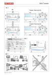
5. Transport (Fig. 3)
The cabinets are supplied on a wooden support fixed to the base for movement with forklift trucks.
Always position the forks at the point specified on the wooden support to avoid the risk of overturning. Use a manual or electrical forklift truck that is suitable to moving the cabinet in question. It
must have a nominal capacity of at least 1,000 kg.
6. Acceptance and first cleaning
Upon acceptance of the cabinet:
- ensure that the packaging is intact and there is no obvious damage;
- unpack, ensuring you do not damage the cabinet;
- check all parts of the cabinet, ensuring that all parts are intact;
- should damage be reported, call the supplier immediately;
- clean for the first time using neutral products. Dry with a soft cloth. Do not use any abrasive
substances or metal sponges;
- do not use alcohol or similar to clean the methacrylate parts (Plexiglas).
For correct disposal of the packaging, please consider that it consists of:
Wood - Polystyrene - Polythene - PVC - Cardboard.
In accordance with Directive EEC 94/62, we declare the suitability of the above-specified materials.
7. Installation and environmental conditions(Fig. 3)
Do not position the cabinet:
- in environments with the presence of explosive gaseous substances;
- outdoors and therefore where there are atmospheric agents;
- near heat sources (direct sunlight,heating systems, incandescent lights, etc.)
- near air currents (near doors, windows, air-conditioning/heating systems, etc.) exceeding speeds of
0.2 m/sec.
- remove the wooden supports at the base (used for transport) and assemble the adjustable feet (Rif.
2), positioning them in such a way as to bring the unit to a horizontal position. Use a spirit level (Rif. 1)
to check this. If the unit is moved, repeat the spirit level check.
- before connecting the unit up to the electricity, ensure that the plate data corresponds to the
characteristics of the electrical system to which it is to be connected.
- for correct unit operation, the environmental relative humidity and temperature must be in line with the
parameters specified by standards EN ISO 23953 -1/2, namely Climatic Class 3 (+25°C; U.R. 60%).
28
05060104 00 13/03/2010
Pelican
English
- check that the ventilation apertures of the condenser unit are not blocked - version with built-in unit.
ATTENTION!: Multiplex up to 3 cabinets on the same electrical and refrigeration supply line (1
master + 2 slaves)
Note:All these operations should be performed by specialised technical personnel.
8. Multiplexing of cabinets (Fig. 11)
To multiplex two or more cabinets, act as follows:
- Remove the sides
- Position the cabinets side by side
- Remove the back panels to gain access to the rise holes
- Join the rises and brackets using the screws supplied
- Replace the back panels.
MULTIPLEX KIT
Ref.
1
2
3
4
5
6
7
8
9
10
11
12
Code
Q.ty
Description
02940652 8
Handrail alignment plug D 4
04711030 2
Screws TCEI M8X80
04711041 1
Screws TCEI M8X50
04230600 7
Hexagonal nut M8
04711040 4
Screws TCEI M8X35
04480112 8
Washer D 8.5x24
04711098 4
Screws TCEI M8X25
04230400 2
Hexagonal nut M6
04480103 4
Washer D 6x12
02940045 2
Lamp alignment plug D 3
04715051 3
Screws TC M5X25
04231100 3
Hexagonal nut M5
9. Electrical connection (Fig. 13 - Fig. 14 - Fig. 15)
- the electrical system must be earthed.
- First check that the voltage supply is as specified on the plate data (Fig. 2)
- The unit must be protected upstream by an automatic omnipolar thermomagnetic switch with
appropriate characteristics. This must also act as a general line disconnection switch.
- Instruct the operator as to the switch position in order that it can be reached quickly in an
EMERGENCY.
- To guarantee correct operation, the maximum voltage variation must be between +/- 6% of the
nominal value.
- Check that the power line has appropriate section cables, is protected against overcurrent and
dispersions towards earth, in compliance with current standards.
- The installer must supply the anchorage devices for all cables in and out of the unit.
- For power lines exceeding 4-5 metres in length, increase the cable section accordingly.
- In the event of an interruption to the electricity supply, check that all store electrical appliances can
reboot without causing the overload protections to intervene. If not, alter the system in order to
differentiate between the start-up of the various devices.
- The installer must supply the anchorage devices for all cables in and out of the unit
- The automatic thermomagnetic switch must be such as not to open the circuit on neutral, without
simultaneously opening it on the phases. In any case, the opening distance of contacts must be at
least 3 mm.
Note:All these operations should be performed by specialised technical personnel.
10.Probe positioning (Fig. 12)
- Temperature probe: NTC IP67 L=4000 code 04510153 .
- Probes A - C must be blocked using Betterman 6-17 terminals code 04355001 and must not be
insulated.
- Probe B must be fixed in contact with the aluminium fins using the stainless steel bulb-holder spring
code 02230134.
11.Temperature control and adjustment (Fig. 5)
The tank and superstructure have two separate temperature control systems.
Refrigeration temperature is controlled by means of the thermometer (Rif. 4) or the electronic control
05060104 00 13/03/2010
29
Pelican
English
device (Rif. 5 OPTIONAL) on the lower part of the cabinet (tank) or the upper part (rise) (Rif. 9). Normally the controller is set in the factory during testing, but it is possible to alter programming. To do so,
please refer to the instructions given by the control device manufacturer.
Economisers
If using electronic systems commonly referred to as 'economisers' (due to the door heating
wire adjustment function), these must be connected to the glass door power supply
only. Connecting the economisers to the frame heating wire power supply lines and not to
the door ones may damage the wires and invalidate the product warranty.
Frame wires must operate at full power.
Note:All these operations should be performed by specialised technical personnel.
12.Unit loading (Fig. 5)
To refill the unit, you must comply with some important rules:
- arrange the goods in such a way that the maximum load line is never exceeded(Rif. 8) - exceeding
this limit can interfere with correct air circulation (Rif. 12), causing the goods temperature to rise and
ice to form on the evaporator;
- arrange the goods in a uniform, orderly fashion avoiding overloading the shelves (maximum load
admissible 160 kg/m2).
- the arrangement of goods, without leaving empty areas, guarantees optimum unit function.
- leave approximately 30 mm space between the goods and the shelf immediately above.
- we recommend using up the goods that have been stored in the unit for longest first, before the new
arrivals (food stock rotation)
- The maximum load admissible in the tank is 300 kg/m2
- Shelves can be angled in 2 different positions 0°; -10°.
ATTENTION!:
To refill the superstructure:
- load the cabinet one door at a time;
- do not load the cabinet with all doors open at the same time;
- block the door open until loading is complete to avoid continuously opening and
closing it, during this phase, keep the sliding cover below open to avoid condensation forming.
Do not load the cabinet roof with boxes, packages or other (Rif. 3)
Do not use the sliding doors as a resting plane for goods when loading. The doors
have not been designed to support any loads (Rif. 6).
12_1.Loading of cabinets for ice cream and frozen foods
- reducing the time for which frozen foods are at environmental humidity and temperature to a
minimum to avoid the formation of frost on the boxes, which can, once inside the cabinet, stick
together and to the base grille.
- limit door opening time to 2-3 minutes
- keep 4-5 cm space between the goods and the air output mouths to allow for normal circulation of
refrigerated air.
Note:Hot air will inevitably enter the cabinet, if humidity levels are high, a
thin layer of frost will form. This will disappear once the doors have been kept closed for 2
hours.
Note:The refrigeration unit is designed to maintain the temperature of the product displayed
and not to lower it.
Food products must only be introduced if already cooled to their respective storage temperatures. DO NOT introduce products that have been heated.
13.Defrost and water draining (Fig. 9)
The tank and superstructure are fitted with two automatic electrical defrost systems. These are separated by armoured electrical resistances inserted into each evaporator:
To drain the defrost water, you need to:
30
05060104 00 13/03/2010
Pelican
English
- set up a gently-sloping floor drain.
- install a siphon between the unit drainage pipe and the floor connection.
- hermetically seal the floor drainage area.
This will prevent unpleasant odours from forming within the unit, the dispersion of refrigerated air and
possible unit malfunctioning due to humidity.
Note:Call a qualified installer to check that the hydraulic connections are perfectly operative on
a regular basis.
14.Anti-condensation and fog resistance
To prevent fogging due to condensation, low voltage electrical resistances are used on the parts most
subject to this, such as: heat-insulating glass on doors, structures and frames, side glass, etc.
15.Maintenance and cleaning (Fig. 6 - Fig. 7 - Fig. 8)
ATTENZIONE!: BEFORE CARRYING OUT ANY MAINTENANCE WORK OR
CLEANING, FIRST DISCONNECT THE UNIT FROM THE VOLTAGE SUPPLY
BY MEANS OF THE GENERAL SWITCH. ALWAYS WEAR PROTECTIVE
GLOVES FOR CLEANING.
Food products can deteriorate due to microbes and bacteria. Compliance with hygiene rules and the
cold chain is fundamental to guaranteeing protection of the consumer's health.
Cleaning the external parts (Daily / Weekly)
- weekly cleaning of all the external parts of the unit, using neutral household cleaners or soap and
water.
- rinse with clean water and dry using a soft cloth.
- DO NOT use abrasive products or solvents that can affect the unit surface.
- DO NOT spray water or detergent on the electrical parts of the unit.
- DO NOT use alcohol to clean the methacrylate parts (Plexiglas).
Cleaning of the internal parts (Monthly)
- remove all goods contained in the cabinet.
- remove all removable parts, such as display plates, grilles, etc.
- wash with warm water and a detergent/disinfectant and dry thoroughly.
- thoroughly clean the bottom tank.
- regularly clean the drip tray and drain, raising the fan sheet if necessary
To wash the cabinet's inner tank with running water, when installing the cabinet you will need to
arrange for a fixed floor drain.
Cleaning the tank's sliding doors (Fig. 7)
- raise the cover profile (fig. A)
- remove the cover (fig. B)
- clean as specified for the cleaning of external parts
- replace the covers
- reposition the cover profile
ATTENTION!: If using a water jet cleaner to clean the interior, use a LOW PRESSURE
system. Take special care NOT direct the jet onto painted or plasticised surfaces and
keep a minimum distance of 30 cm from the surface to be cleaned (Fig. 4).
16.Cleaning the EVERCLEAR doors (optional) (Fig. 6)
ATTENTION!: EVERCLEAR doors are glass doors with a special transparent interior cover that
prevents condensation from forming.
To clean EVERCLEAR doors, keep to the following instructions:
- open and block the door
- carefully clean the interior with a soft, damp cloth appropriate to cleaning parts that may come
into contact with food products
- use neural detergents or soap and water
- change the cloth frequently
- close the door
- clean the exterior wall of the door using neutral household detergents or soap and water
- rinse with clean water and dry using a soft cloth
05060104 00 13/03/2010
31
Pelican
English
- DO NOT use abrasive products or solvents that can affect the door surface
ATTENTION!: DO NOT CLEAN THE DOOR INTERIOR WITH THE SAME PRODUCT
USED TO CLEAN THE EXTERIOR. DO NOT USE ANY ABRASIVE PRODUCTS OR SOLVENTS THAT COULD AFFECT THE INTERIOR DOOR SURFACES. DELLE PORTE
17.Lighting (Fig. 5 - Fig. 10)
For external lighting, a lighting system supplied with a modular fitting to be applied externally to the top
of the cabinet is available as an optional extra (Rif. 10).
For tank front lighting, a lamp can be installed on the handrail (optional) (Rif. 11).
OPTIONAL: For greater energy savings, the cabinet can be ordered complete with low
consumption LED lighting. This allows for:
- reduced lighting consumption
- reduced refrigerator load
- duration of lights: more than 6 years
- uniform lighting colour and intensity on all doors at all times
- improved lighting as temperature decreases.
18.Bulb replacement (Fig. 5 Rif. 13)
Replace the bulbs as follows:
- Disconnect the electricity supply from the cabinet.
- Remove fixing screws A from the protective casing.
- Remove caps B and protective casing C.
- Rotate bulb D by approximately 90° (until it clicks into place) and remove from the bulb-holder.
- Replace the bulb.
- Re-insert the casing and caps fixing them with the screws.
- Restore the electricity supply.
19.Disposal of the cabinet
The unit must be disposed of in accordance with your country’s waste management legislation and in
respect of our environment.
This product is considered by current legislation as hazardous waste. It must therefore be collected
separately and cannot be treated as household waste nor sent to a landfill. Before disposing of the unit,
the coolant must be collected and the lubricant oil removed. The user is responsible for delivering the
product for disposal to the collection centre specified by the local authorities or manufacturer for the
recovery and recycling of materials. This product consists of 75% recyclable materials.
Materials used to build the cabinet:
- Iron tube:
lower frame and support structure
- Copper, Aluminium:
refrigeration circuit, electrical system and door frame
- Galvanised sheet metal:
motor base, lower panels, varnished panels, base structure
- Polyurethane foam (CO2):
heat insulation
- Tempered glass:
front glass and doors
- Wood:
side frames foamed tank
- PVC:
bumper
- Plastic laminate:
sides
Note:All these operations as for transport and waste processing, should be performed by
authorised, specialised personnel only.
20.Useful advice
We recommend careful reading of the Use and installation manual to ensure that in the event of failure,
the operator is able to provide Technical Assistance with the specific information required.
Before carrying out any maintenance work on the refrigerator unit, please ensure that the
electrical supply is disconnected.
If a customer should note any anomaly in the unit function, before contacting the Assistance Service,
check the following points:
- Take great care over all working manoeuvres (loading, unloading, cleaning, counter service,
maintenance, etc.). and always apply maximum diligence, using appropriate protective equipment for the various operations.
32
05060104 00 13/03/2010
Pelican
English
- Take great care over all working manoeuvres (loading, unloading, cleaning, counter service,
maintenance, etc.). Always use the personal protection equipment (PPE) provided for the operations
to be performed.
- check that the environmental humidity and temperature values do not exceed those specified, always
keep the sales outlet's air-conditioning, ventilation and heating systems at maximum efficiency.
- limit ambient air speed to below 0.2 m/s near unit openings. Ensure that air currents and airconditioning system supply outlets are not directed towards unit openings.
- do not expose the goods displayed to direct sunlight.
- limit the temperature of the radiating surfaces in the sales outlet, for example by insulating ceilings.
- do not use spotlights with incandescent bulbs directed straight onto the unit.
- do not fully or partially block the air suction and delivery outlets.
- only place goods into the cabinet at the temperature normally applicable to the cold chain and check
that the cabinet is always able to maintain that temperature.
- comply with the load limit, avoiding overloading the cabinet.
- rotate food products by loading the cabinet in such a way that the goods displayed for longest are
sold before new arrivals.
- regularly monitor unit operating temperature and the temperature of the goods displayed (at least
twice a day, including at weekends).
- in the event of a black-out, close the cabinet with the night shade. If the suspension of the electricity is
scheduled, close the cabinet with the shades at least a couple of hours prior to this, preparing
function for maximum operation.
- should the unit break down, immediately take all steps to ensure that the refrigerated goods do not
overheat (replace in the main cell, etc.).
- immediately eliminate any problem found (loose screws, blown bulbs, etc.).
- regularly check the function of the unit automatic defrost (frequency, duration, air temperature,
restoration of normal operation, etc.).
- check the outward flow of the water resulting from the defrost (free up the drains, clean any filters,
check the siphons, etc.).
- if abnormal condensation forms, inform the refrigeration technician immediately.
- regularly carry out all preventative maintenance works.
- dispose of defrost water or water used for washing through the drains or purification system in
accordance with current legislation as this may come into contact with pollutants due to the nature of
the product, any residues, accidental breakages of casing containing liquids and the use of nonpermitted detergents.
- IN THE EVENT OF A GAS LEAK OR FIRE: Do not stay in the room where the cabinet is positioned if
it is not appropriately ventilated. Disconnect the unit by means of the general switch upstream of the
appliance. DO NOT USE WATER TO EXTINGUISH FLAMES. ONLY USE DRY EXTINGUISHERS.
- DO NOT stand on the bumper rail
ALL OTHER USE NOT SPECIFICALLY PROVIDED FOR IN THIS MANUAL SHOULD BE
CONSIDERED DANGEROUS. THE MANUFACTURER CANNOT BE HELD LIABLE FOR
DAMAGES CAUSED BY IMPROPER, INCORRECT AND UNREASONABLE USE.
USEFUL TELEPHONE NUMBERS:SWITCHBOARD +39 0499699333 - FAX +39 969944 - CALL
CENTRE 848 800225
05060104 00 13/03/2010
33
Pelican
English
1. Assembly indications for inverting the doors
ATTENTION!: Cut off power supply to the cabinet before proceeding with all operations
Brema 5 - Brema LF refrigerated wall cabinet is normally supplied in the version with right-hand opening doors. If required, the direction of door opening can be inverted from right to left ..
N.B.Is not possible to invert one or more doors individually.
30 minutes are sufficent for this operation and the collaboration of 2 workers is recommended.
Equipment required:
Hammer - Spatula - Drill - Drill bit Dmax= 9mm - Pliers - Pliers for elastic rings - Hexagonal spanners 2/
3/4 - Cross-head Screwdriver - Metal pipe / spacer .
In order to invert the doors, follow the indications below:
1 Detach the spring-loading spanner from
its housing
2 A) Insert the spring-loading spanner into one
of the holes ofthe lower pin.
Insert the spring-loading spanner into one of
the holes ofthe lower pin.
B) Keeping the spanner still in the position
indicated, remove the spring-loading pin and
place both the pin and the spanner in a safe
place.
1 - Loading pin 2 - Spring-loading spanner
A
B
(1)
(2)
3 A) Remove the screws
that fix the wiring
protection
plate in
place.
B) Pull out the cable.
C) Pull out the connector
D) Open the connector
4 (referred to the right and left-hand risers).
This phase applies both for dismantling
the right-hand door and for preparing the
left-hand rise.
A) Remove the side buffer profile using a
spatula
B) Pull out the cable and open the connector
34
B
A
A
C
D
B
05060104 00 13/01/2010
Pelican
English
5 Loosen the screws that fix the antifraying fork on the upper part of the
door. Let the fork slide and rotate it as
indicated in figure A:
A
A
6 In order to remove the door, it must be
lifted and simultaneously rotated as
indicated in the drawing so that it is
first released from its housing on the
bottom part. Given the weight of the
door the collaboration of two workers
is recommendedl.
N.B.If difficulties are encountered
while removing the door, use a lever in
wood or other similar material so not
to damage the door itself. Delicately lift
the door a few millimetres so as to
withdraw the pin of the lower hinge.
Do not exert unneccessary force
7 Remove the door and place it on a flat
horizontal surface so as to carry out
the inversion operation in the best way
possible. Fully remove the entire lower
hinge unit.
A) Remove the screws (1) and (2)
using the respective spanners
B) Remove the lower hinge uni
C) Withdraw everything, including the
galvanised block
D) Dismantle the galvanised block unit
(3)
E) Remove the elastic ring that holds
the sleeve in place (4) using the appropriate pliers
F) Remove the lower pin-guide sleeve
(5)
(2)
(1)
(3)
A
D
B
E
(4)
C
F
(5)
(3)
05060104 00 13/01/2010
35
Pelican
English
8 Remove the universal door-blocking
bracket (1)
9 Transform the universal bracket from
right to left.
A) Right-hand bracket
B) Remove the lower brass (1);
C) Turn the bracket upside down and
insert the brass
D) Left-hand bracke.
10 A) With the utmost delicacy, remove
the upper hinge from the upper part of
the door, making sure not to exert
excess stress on the coupling between
the pin and the plastic bush;
B) Also dismantle the anti-fraying fork
(1).
(1)
A
B
C
D
A
B
(1)
11 Re-mount the lower hinge unit, having
now become a left-hand unit, following
phases 8-9 backwards and insert it in
place of the upperhinge.
36
05060104 00 13/01/2010
Pelican
English
12 Mount the upper hinge unit where the lower
hinge was previously situated.
A) Re-mount the anti-fraying fork
B) Insert the upper hinger using a metal pipe D
16 (1)
C) Beat gently on it until the upper hinge has
been fully inserted
D) ABSOLUTELY DO NOT BEAT DIRECTLY
B
A
(1)
D
C
13 Dismantle the lower plate unit..
14 Place the previously dismantled lower
plat unit
on a flat surface, remove the upper
plate (1),
remove the ratchets (2) and place
them in their
new housing as indicated in figure B.
Rotate the spring (3) by 180°
A
(1)
(2)
(3)
(2)
B
(1)
05060104 00 13/01/2010
(2)
(3)
(2)
37
Pelican
English
15 A) Remove the plugs that seal the
frame holes;
B) Position the previously prepared
plate in correspondence with the frame
holes
(1)
A
16 A) Remove the upper plaque in nylon
from the cabinet riser.
B) Using a bit of max 9 mm, drill in
correspondence with the predisposed
hole on the left side, so as to create a
housing for the pin of the upper hinge
Avoid off-axis or inclined holes.
Drilling depth: min.18 mm max 24 mm.
C) Re-position the nylon plaque in its
new position using the respective
screws
A
B
B
C
17 At this point, re-mount the now lefthanded door, making sure to first insert
the upper hinge in the hole previously
created and to subsequently position it
slowly in such a way as to insert the
lower pin in the respective hole of the
lower plate unit.
As in dismantling, if difficulties are
encountered.
18 Restore the electric connection, taking
care to rotate the plaque (1) by 180° so
that the words ”left door” appear on
the upper part of the plaque itself.
A) Close the connector;
B) Re-insert the cable;
C) Tighten the screws (1)
A
B
C
19 Insert the spring-loading spanner into
one of the holes of the lower pin, rotate
in an anti-clockwise direction so as to
insert the loading pin. When the
operation has been completed, the
door should close automatically. If it is
not sufficiently loaded, move the
loadingpin by one hole
38
05060104 00 13/01/2010
Pelican
English
HINGE UNIT
1) Galvanised block for curved spring
2) Threaded galvanised block for curved
spring
3) Burnished screw M4x8
4) Hook-shaped square-section spring
5) Lower pin-guide sleeve
6) Universal door-block bracket
7) Screw
8) Screw
9) Lower brass
10) Universal galvanised Seeger ring
11) Square spring lower pin w/ radial holes
12) Spring-loading pin
2
4
1
3
5
6
8
7
9
10
11
12
PLATE UNIT
1) Door-blocking spring
2) Plate fixing stainless steel screws
3) Blanked plate
4) Ratchet for peg
5) Pin for door-blocking spring
6) Nylon under-plate
1
2
2
3
4
5
4
6
05060104 00 13/01/2010
39
I
Ci riserviamo il diritto di apportare in qualunque momento, le modifiche alle specifiche e ai dati
contenuti in questa pubblicazione senza obbligo di avviso preventivo.
La presente pubblicazione non può essere riprodotta e/o comunicata a terzi senza preventiva
autorizzazione ed è stata approntata per essere utilizzata esclusivamente dai nostri clienti.
GB
We reserve the right to change our technical specifications without notice.
This brochure may not be reproduced, nor its contents disclosed to third parties without arneg’
s consent and it is meant only for use by our customers.
D
Änderungen der in dieser Broschüre enthaltenen Angaben und Informationen voberhalten.
Diese Broschüre darf ohne usere ausdrückliche Genehmigung weder vervielfältigt noch an
Dritte weitergegeben werden und sie ist ausschließlich für unsere Kunden bestimmt.
F
Nous nous réservons le droit d’apporter à tout moment des modification aux spécifiques et
aux caractéristiques contenues danse cette publication, sans aucune obligation de préavis de
notre part. Cette publication ne peut être reproduite et/ou communiquée â des tiers sans
autorisation préalable. Elle a été réalisée pour étre utilisée exclusivement par nos clients.
E
Nos reservamos el derecho de aportar en cualquier momento las modificaciones a las
especificaciones y a los datos contenidos en esta publicació sin ninguna obligación de aiso
anticipado.La presente publicación no puede ser reproducida y/o comunicada a terceros sin
la previa autorización y ha sido aprontada para ser utilizada exclusivamente por nuestros
clientes.
RUS
!
"#$" & .
*& / " <>
> & $" $ > $@ <Z $ .
Arneg SpA - Via Venezia, 58 - 35010 Campo San Martino - (PD) Italia - Tel. +39 049 9699333 - Fax +39 049 9699444 - www.arneg.com - Cap. Soc. € 43.000.000 i.v.
Certified ISO 9001:2008 e ISO 14001:2004 - C.F./P.IVA/Reg.Imprese Pd IT 00220200281 - R.E.A. Padova n. 94246 - Meccanograf. PD009504 - RAEE IT8010000000139