1
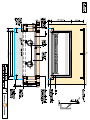
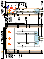
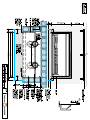
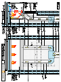
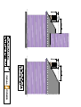
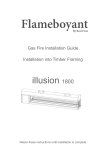
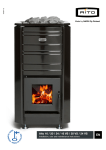
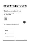
Real Fires Standard Range installation instructions
Model 1500
INSTALLATION INTO TIMBER FRAMING
AND NEW MASONRY BLOCK CONSTRUCTION
New Masonry Block The following instructions are for installation into timber frame.
The method of installation is the same for New Masonry Block.
See Masonry Block Drawing
Ventilation
Ventilation to the room that houses the fire must meet the requirements of NZS5261
Framing Details
Prior to installation, timber framing needs to be provided to suit the selected Real
Fire. See installation drawing
Hearth
A non combustible Hearth must be provided in front of the Real Fire unless the
flooring in front of the fire is non combustible. The minimum size is 300mm out from
the fire and 150mm each side wider than the fire.
Height of fire from floor
It is important to confirm the height the fire is to be installed from the floor level. This
is usually the hearth height. For example if the hearth is 100mm high then the fire
needs to be installed 100mm high. (note- some elevated installations specify the fire
higher than the hearth). Once the height is confirmed a platform needs to be built to
support the firebox. The platform can be of timber construction. It needs to be sturdy
and level.
Gas Supply
A suitable gas supply needs to be provided at the right hand rear corner of the timber
frame cavity. The pipe sizing should be calculated to supply gas to suit the megajoule
rating of the fire. See rating chart. The gas supply should be reduced down to 10mm
copper pipe at the fireplace location and left with a coil of approx 1metre to feed into
the firebox.
Gas Rate Chart
Model
650
700
800
900
1000
1200
1500
L.P.G.
36 Mj/Hr
38 Mj/Hr
41 Mj/Hr
44 Mj/Hr
53 Mj/Hr
63 Mj/Hr
70 Mj/Hr
Natural Gas
38 Mj/Hr
40 Mj/Hr
43 Mj/Hr
46 Mj/Hr
55 Mj/Hr
65 Mj/Hr
74 Mj/Hr
Electrical supply
An electrical supply will be required for fires fitted with the optional Fan Set or
Electric On/Off. This should be by means of a wall switch provided by an electrician,
located preferably at the left side of the fireplace. Not inside the framing cavity.
See installation drawing for preferred location of switch.
Insulation Kit & Timber Clearance
When installed into timber framing the Real Fire must be installed with an insulation
kit. This must be ordered with the fire and fitted in the factory by Real Fires.
The insulation kit allows the firebox to be installed with minimal timber clearances:
10mm clearance on sides of firebox and 25mm clearance from rear and top of firebox
The timber clearance from the twin wall flue is also 25mm.There is no requirement
for any additional fireproof materials within the fireplace cavity providing minimum
clearances are allowed.
Recessed firebox installation
Standard wall linings are not suitable for recessed installation. Please contact
Real Fires for advice prior to installation
Flue requirements
The minimum flue height is 2.4 metres (straight flue – no bends)
The flue cowl should be no lower than 900mm vertically from the roof line and a
2 metre horizontal clearance from any part of the building see cowl clearance
drawing
Flue and Cowl Size
Real Fire 650 150mm inner flue/ 200mm outer flue
Real Fire 700 150mm inner flue/ 200mm outer flue
Real Fire 800 200mm inner flue/ 250mm outer flue
Real Fire 900 200mm inner flue/ 250mm outer flue
Real Fire 1000 200mm inner flue/ 250mm outer flue
Real Fire 1200 250mm inner flue/ 300mm outer flue
150/200 Cowl
150/200 Cowl
200/250 Cowl
200/250 Cowl
200/250 Cowl
250/300 Cowl
The Real Fire 1500 has Two Flues
There are two flue spigots on top of the insulation kit.
Two 150mm/200mm x 1200mm long sections of flue are connected to the spigots.
The two flues are then connected to a special Y piece, this is a transition to join the
two flues into one.
From the Y piece a single 250/300mm flue kit is used with a 250/300 cowl.
Installation instructions
Firstly the firebox and flue are installed and then the burner is installed. The burner
may be installed at a later date when all the construction work is complete and the
hearth is in place.
The firebox is placed on the platform provided and the gas pipe is pushed through the
hole at the right hand rear of the firebox ( RH from the front of the fire).
This pipe is to be connected to the burner but may be left sealed if the burner is to be
installed later. Leave enough pipe to connect the burner.
Once the firebox is in place ensure it is level. Usually the firebox is positioned
centrally and so that the flange around the firebox opening is left forward of the
timber framing by 10mm, this is to allow for giboard to be fixed behind the flange.
From the positioned firebox the flue can be assembled. The flue is in 1200mm lengths
with both inner and outer flue. Each flue length has a crimped end to join tightly to
the next length. Each joint must be securely fixed by at least three stainless steel
rivets. The firebox has a spigot for the flue to locate over.
The flue lengths should be installed with the crimped end facing up.
The Firebox and flue should be secured by fixing with seismic strapping and/or
brackets to framing.
Flue bends are available from Real Fires if the flue needs to be offset.
Appropriate weatherproof roof flashing/ chimney capping must be used to comply
with NZS 5261
Once the installation of the firebox and flue is complete, the building work around the
fireplace can continue. A timber cross frame is usually fixed above the firebox for gib
fixing. This must be at least 25mm from the firebox.
The firebox will have two electrical leads from the rear of the firebox
All fireboxes are pre wired for the electrical options, Fan and Electric On/Off.
The leads are approximately 1.2m long and are intended to be connected by an
electrician to a switch positioned facing the room preferably on the left hand side of
the fireplace cavity. See installation drawing
(Please ensure the electrical leads are not left behind the firebox and overlooked. It is
difficult to gain access once the giboard is fixed)
Timber surround
If a timber surround is to be fitted, ensure it complies with Real Fires minimum
clearance dimensions. See installation drawing
Installation of Real Fires burner into firebox
The burner is supplied boxed complete with, firebox reflectors, grate, ash cover,
vermiculite, logs, & coals.
To make the gas connection, place the burner in the firebox so that the back of the
burner is touching the firebox and it is positioned central. The gas pipe should be bent
into position & marked for cutting. Remove the burner, cut the pipe and make a flare
connection.
Re fit the burner into the firebox ensuring it is touching the back of the firebox.
Connect the gas pipe. Test for soundness.
Remove plastic protective film from side reflectors. Position reflectors each side of
firebox and fit the front Grate onto the brackets at the front of the burner.
The Grate holds the reflectors in place.
Natural Gas Burner
Fill the burner tray with the vermiculite supplied ensuring the burner tube is
completely covered.
Lay logs and coals on top of the vermiculite as shown in the Log/coal layout
drawing. Note that the shelf at the back of the burner is also used. Do not place coals
or logs close to the pilot.
It is important that the coals are not too tightly placed as this will affect the heat
output. The flame picture and radiant glow is better when there is good spacing
between the coals.
L.P.G. Burner
The L.P.G. burner is a flat steel burner. This burner is supplied with a bag of coarse
vermiculite, spread this thinly (5 to 10mm) over the surface of the burner.
Follow instructions for coal placement as with Natural Gas burner.
Optional Electric On/Off Option
If the burner is fitted with an electric on off solenoid, there will be an electrical lead
with a connector plug in the base of the fire. The plug connects to the solenoid.
The electrical lead should be connected to a wall switch by an electrician.
The burner will not operate without the solenoid on.
Commissioning of the Burner
Turn the control knob to ignite the pilot, this may take several attempts until air has
been purged. Once the pilot is alight, keep the control knob depressed for about 20
seconds. Then release and turn on the main burner. Check that the flame travels easily
across the burner and that coal placement does not affect ignition.
Re- position coals if required.
Burner Gas pressure
Check burner gas pressure from the test point on the burner supply pipe on the
Natural Gas Model and on the injector elbow on the L.P.G. model.
See appliance data badge for pressure settings.
Adjust the pressure at the regulator if required.
Check the fire is operating correctly and test for spillage of combustion products.
Fitting Trim to Firebox
Fit the Stainless Steel or Black trim to the firebox. The trim brackets are designed to
hang over the flange on the front of the firebox. The flange has provision to be moved
slightly in or out to allow the bracket to fit. The flange on each side of the firebox has
a raised square near the base of the fire. The Velcro pad is fixed to this, by removing
the backing from one side of the pad and pushing firmly in place. Then remove
backing from other side. Repeat on opposite side. Hang trim on brackets and check
for level then push firmly onto Velcro pad.
Optional Fan
If a fan has been selected with the fire, it will be already fitted in the firebox at the
factory. It is controlled by a wall switch which should be fitted by an electrician.
There is no electrical switching within the fire and the wall switch is not supplied
by Real Fires.
Once the installation is complete, instruct the user on the operation of the fire and
complete commissioning details in Real Fires user manual.
All installations must be Certified
Real Fires Log and Coal Layout
This drawing is a typical example of the log and coal layout on a Real Fire 800
The layout is basically the same for all models with logs and coals decreased or increased in width
to suit the size of fire. (The pilot ignition assembly has been omitted from the drawing).
It is important to ensure that the logs and coals are not too tightly placed as this will affect heat
output. Do not place Logs and Coals close to the pilot and ensure that the burner lights easily and
flame travels easily across the burner. Reposition if required.