1
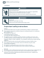
Installation instructions
and User guide
Freestanding cooker
OR60 & OR90 models
NZ
Contents
Safety and warnings
Installation instructions - OR60 models
Installation instructions - OR90 models
Using your oven
Cooking functions
Using your gas cooktop
Cooktop troubleshooting
Care and cleaning
Warranty and service
1
2
6
14
24
26
27
31
32
40
Important!
SAVE THESE INSTRUCTIONS
The models shown in this User Guide may not be available in all markets and are
subject to change at any time. For current details about model and specification
availability in your country, please go to our website www.elba.co.nz or contact your
local Fisher & Paykel dealer.
2
Safety and warnings
Installation
WARNING!
Electrical Shock Hazard
Always disconnect the cooker from the mains electricity supply before
carrying out any maintenance operations or repairs.
Failure to follow this advice may result in death or electrical shock.
WARNING!
Cut Hazard
Take care - panel edges are sharp.
Failure to use caution could result in injury or cuts.
Important safety instructions
General
To avoid hazard, follow these instructions carefully before installing or using this product.
Please make this information available to the person installing the product as it could reduce
your installation costs.
These products are registered:
in New Zealand at www.ess.govt.nz
in Australia with AGA at www.gas.asn.au.
This appliance must be installed in accordance with these installation instructions, local
gas fitting regulations, municipal building codes, water supply regulations, electrical wiring
regulations, AS5601 / AG 601 and NZS5261 - Gas Installations and any other relevant statutory
regulations.
Failure to install the cooker correctly could invalidate any warranty or liability claims.
Some appliances have a protective film. Remove this film before using the cooker.
Do not modify this appliance.
This appliance is to be installed and serviced only by an authorised person.
This appliance MUST NOT be installed in marine craft, caravans or mobile homes .
Electrical
This cooker is to be installed and connected to the electricity supply only by an authorised person.
If the installation requires alterations to the domestic electrical system, call a qualified
electrician. The electrician should also check that the electrical system is suitable for the
electricity drawn by the cooker.
Safety and warnings
3
The appliance must be connected to the mains electricity supply, checking that the voltage
corresponds to the value given in the rating plate and that the electrical cable sections can
withstand the load specified on the plate.
A suitable disconnection switch must be incorporated in the permanent wiring, mounted and
positioned to comply with the local wiring rules and regulations. The switch must be of an
approved type installed in the fixed wiring and provide a 3 mm air gap contact separation in all
poles in accordance with the local wiring rules.
In Australia and New Zealand, a switch of the approved type with a 3 mm air gap must be
installed in the active (phase) conductor of the fixed wiring.
The switch must always be accessible.
The power supply cable must not touch any hot parts and must be positioned so that it does not
exceed 75 OC at any point.
To connect the cooker to the mains electricity supply, do not use adapters, reducers or branching
devices as they can cause overheating and burning.
If the electrical supply cord is damaged, it must only be replaced by an authorised person.
This cooker must be connected to electrical supply using V105 insulated cable (3 x 1.5 mm2
section).
The cooker must be earthed.
Power supply
OR60 models: 230-240V ~ 2460-2680W 50Hz
OR90 models: 230-240V ~ 3345-3640W 50Hz
4
Safety and warnings
Operation
Your freestanding cooker has been carefully designed to operate safely during normal cooking
procedures. Please keep the following guidelines in mind when you are using it:
WARNING!
Explosion Hazard
Do not store flammable materials such as gasoline near the cooktop.
Do not store flammable material in the oven, drawer or storage
compartment.
Do not spray aerosols near the cooktop during use.
Failure to follow this advice may result in death or serious injury.
WARNING!
Electrical Shock Hazard
Switch the cooker off at the wall before replacing fuses or the oven lamp.
Failure to do so may result in death or electrical shock.
WARNING!
Hot Surface Hazard
Accessible parts may become hot when this cooker is in use.
To avoid burns and scalds keep children away.
Do not touch hot surfaces inside the oven.
Use oven mitts or other protection when handling hot surfaces such as oven
shelves or dishes.
Take care when opening the oven door.
Let hot air or steam escape before removing or replacing food.
Do not touch the cooktop components, burners, trivets/pan supports or the
base when hot.
Before cleaning, turn the cooker off and make sure it is cool.
Failure to follow this advice could result in burns and scalds.
Safety and warnings
5
Important safety precautions
Never leave the appliance unattended when in use. Boilover causes smoking and greasy
spillovers that may ignite.
Isolating switch: make sure this cooker is connected to a circuit which incorporates an isolating
switch providing full disconnection from the power supply.
Household appliances are not intended to be played with by children.
Children, or persons with a disability which limits their ability to use the appliance, should have a
responsible person to instruct them in its use. The instructor should be satisfied that they can use
the appliance without danger to themselves or their surroundings.
Safe food handling: leave food in the oven for as short a time as possible before and after
cooking. This is to avoid contamination by organisms which may cause food poisoning. Take
particular care during warmer weather.
Do not place aluminium foil, dishes, trays, water or ice on the oven floor during cooking as this
will irreversibly damage the enamel.
Do not line the walls with aluminium foil.
Do not stand on the door, or place heavy objects on it.
Do not use harsh abrasive cleaners or sharp metal scrapers to clean the oven door glass since
they scratch the surface, which may result in shattering of the glass.
Do not use a steam cleaner to clean any part of the cooker.
Do not use an asbestos mat or decorative covers between the flame and the saucepan as this may
cause serious damage to your cooktop.
Do not place aluminium foil or plastic dishes on the cooktop burners.
Do not let large saucepans or frying pans overlap the bench as this can deflect heat onto your
benchtop and damage the surface.
Do not let large saucepans, frying pans or woks push any other pans aside. This could make them
unstable or deflect heat onto your benchtop and damage the surface.
Saucepan handles may be hot to touch. Ensure saucepan handles do not
overhang other gas burners that are on. Keep handles out of reach of children.
If the electrical supply cord is damaged, it must only be replaced by an authorised person.
This cooker is not to be used as a space heater.
The use of a gas cooking appliance results in the production of heat and moisture in the room in
which it is installed. Ensure the kitchen is well ventilated. Keep natural ventilation holes open or
install a mechanical ventilation device (mechanical extractor hood).
Prolonged intensive use of the appliance may call for additional ventilation, for example opening
of a window, or more effective ventilation, for example increasing the level of mechanical
ventilation where present.
6
Installation instructions
Installation clearances and protection of combustible surfaces shall comply with the current
local regulations eg. AG 601 (AS5601/NZS5261) Gas Installations code. Installation shall comply
with the dimensions in Fig. 1, bearing in mind the following requirements:
Overhead Clearances
In no case shall the clearance above the highest part of the cooker be less than 600 mm or, for
an overhead exhaust fan, 750 mm. AII other downward-facing combustible surfaces less than
600 mm above the cooker surface shall be protected for the full width of the cooking surface in
accordance with the standards noted above. In no case shall the clearance be less than 450 mm.
Rear and Side Clearances
Where the distance from the periphery of the nearest burner to any vertical combustible surface
is less than 200 mm, the surface shall be protected in accordance with the standards to a height
of not less than 150 mm above the cooking surface for the full width or depth of the cooking
surface.
Where the distance from the periphery of the nearest burner to any horizontal combustible
surface is less than 200 mm, the horizontal surface shall be more than 10 mm below the surface
of the cooking surface, or the horizontal surface shall be above the trivet (see requirements for
vertical combustible surfaces above).
Protection of combustible surfaces
The standards above specify that, where required, protection shall ensure that the surface
temperature of combustible surfaces does not exceed 65°C above room temperature.
Do not install the cooker near flammable materials (eg curtains).
500 mm
450 mm
If you stand the cooker on a pedestal, make sure you provide safety measures to keep it in place.
750 mm
OR60 MODELS
Dimensions and clearances
105 mm
Fig. 1 Dimensions and
distances from cooker
Cooker overall dimensions [mm]
• height:
min 900 - max 915
• product width: 598
• depth:
600
• cavity width
600
Installation instructions
7
OR60 MODELS
Levelling the cooker
Important!
Using the supplied adjustable feet is
MANDATORY. For safety reasons and to
ensure adequate ventilation, the cooker
chassis MUST NOT sit directly on the floor, a
plinth, or other support surface.
1
2
3
To fit the adjustable feet:
Rest the rear of the cooker on a piece of
packaging, exposing the base for fitting
the feet.
Screw the four feet to the cooker.
Stand the cooker and level it by
screwing or unscrewing the feet
with an adjustable spanner. Use the
supplied nuts if necessary, see Figs. 2b
and 2c.
Fig. 2a Fitting the adjustable feet
(supplied with the cooker in the feet kit)
0
+ 8 mm
Fig. 2b Do not use the supplied nuts for height
adjustments between 0 and 8 mm.
+8
mm
+ 15
mm
Fig. 2c Use the supplied nuts for height
adjustments between 8 and 15 mm.
8
Installation instructions
Fitting the anti-tilt bracket
OR60 MODELS
Important!
600 mm
To restrain the appliance and prevent it tipping
accidentally, fit a bracket to its rear to fix it
securely to the wall. Make sure you also fit the
supplied lock pin to the anti-tilt bracket.
2
To fit the anti-tilt bracket:
After you have located where the cooker
is to be positioned, mark on the wall the
place where the two screws of the anti-tilt
bracket have to be fitted. Please follow the
indications given in Fig. 3a.
Drill two 8 mm diameter holes in the wall
and insert the plastic plugs supplied.
235
0
15
++15
min 105
max 120
1
365
(Cavity width
)
Fig. 3a Fitting the anti-tilt bracket
Important!
Before drilling the holes, check that you will not
damage any pipes or electrical wires.
3
4
5
6
7
Loosely attach the anti-tilt bracket with the
two screws supplied.
Move the cooker to the wall and adjust the
height of the anti-tilt bracket so that it can
engage in the slot on the cooker’s back, as
shown in Fig.3a.
Tighten the screws attaching the anti-tilt
bracket.
Push the cooker against the wall so that the
anti-tilt bracket is fully inserted in the slot
on the cooker’s back.
Access the bracket and fit the lock pin:
Remove the drawer (Fig. 3b).
Fit the lock pin through the bracket,
as shown (Fig.3c).
Refit the drawer.
Fig. 3b Removing the drawer
Anti-tilt bracket
attached on the
rear wall
Cooker’s
back
1
Lock pin
Slot on the
cooker’s back
2
Lock pin
correctly fitted
Fig. 3c Fitting the lock pin through the bracket
Installation instructions
9
The gas connection must be carried out by an authorised person according to the relevant
standards.
Before connecting the appliance to the gas main, mount the brass conical adaptor onto the gas
inlet pipe, upon which the washer has been placed (see Figs. 4-5 following).
Conical adaptor and washer are supplied with the appliance (packed with conversion kit for use
with Natural gas or LPG).
This appliance is suitable for use with Natural gas or LPG gas. (Check the “gas type” sticker
attached to the appliance).
For Natural gas, connect the gas supply to the gas pressure regulator which is supplied with the
appliance (Fig.5). Adjust the regulator to obtain a test point pressure of 1 kPa with the two semirapid burners operating at the maximum.
For LPG, connect the gas supply to the test point adaptor which is supplied with the appliance
(Fig.4). Ensure that the supply pressure is regulated to 2.75 kPa.
The connection must be made at the rear of appliance (left or right); the pipe is not to cross the
cooker.
Close off the unused inlet with the cap and sealing washer supplied (Fig. 7).
IMPORTANT: Use two spanners to tighten or loosen the connecting pipe (Fig.6).
Installation with a flexible hose assembly
If this appliance has to be installed with a hose assembly, the installer shall refer to the network
operator or gas supplier for confirmation of the gas type, if in doubt.
When used with a flexible hose, the connector on the wall should be between 450 mm to 500
mm from the floor and 200 mm to 300 mm from the left-hand side of the appliance as viewed
from the front. The hose connection on the appliance shall face downwards.
Gas connection for
NATURAL GAS
Gas connection for
LPG
Gas inlet pipe
Gas inlet pipe
Nipple
Nipple
Washer
Washer
Brass conical adaptor
(Thread tight: use
suitable seal)
Test
point
Brass conical adaptor
(Thread tight: use
suitable seal)
Test point adaptor
Gas pressure
regulator
Test
point
Fig. 4 LPG connection
Fig. 5 Natural gas connection
OR60 MODELS
Connecting the cooker to the gas supply
10
Installation instructions
OR60 MODELS
It is important that the hose does not come in contact with the metal of the appliance and is
secured as per appropriate gas installation codes. A chain 80% of the length of the flexible gas
hose must be used to prevent stress being applied to the hose. The chain should be attached
securely to the product where shown (see Fig.7), and on the wall.
Flexible hose assemblies should be AS/NZS 1869 Class B or Class D certified. The thread
connection shall be Rp ½” (ISO 7-1) male.
Important!
After connection the installer must check that the hose is not kinked, subjected to abrasion or permanently
deformed. The installer must check also that the hose is not near (or in contact with) any hot surfaces.
The hose assembly shall be as short as practicable and comply with relevant AS5601 / NZS5261
requirements.
Leak-testing and flame-testing the cooker
1
2
3
4
After installing the freestanding cooker and connecting the gas supply:
Using a suitable leak detection fluid solution, check each gas connection one at a time by
brushing the solution over the connection.
The presence of bubbles will indicate a leak. If there is a leak, tighten the fitting and then
recheck for leaks.
Important! Do not use a naked flame to test for leaks.
Adjust the test point pressure or supply pressure to the value that is appropriate for the gas
type.
Test the operation of the appliance:
Turn on the appliance gas controls and light each burner individually and in combination.
Check for a well-defined blue flame without any yellow tipping. If any abnormality is
evident, then check that the burner cap is located properly and the injector nipple is
aligned correctly.
Check the minimum burner setting by quickly rotating the gas control knob from the
maximum to the minimum position. The flame must not go out. If you need to adjust the
setting, see ‘Adjusting the minimum burner setting’ following.
If satisfacfory performance cannot be obtained, the installer shall check the installation and
notify the local gas supply authority for a gas supply problem, or if it is an appliance problem,
our Customer Service Centre should be called to obtain the nearest authorized Service Agent.
Cap
Fig. 6 Adjusting the connection pipe
Fig. 7 Gas supply inlets
Installation instructions
11
This appliance is suitable for use with Natural gas or LPG (check the “gas type” sticker attached
to the appliance). To convert from one gas type to another, you need to replace the injectors,
and then adjust the minimum burner setting.
1
2
3
4
Replacing the injectors
Remove the trivets and burners from the cooktop.
Using a spanner, remove the injector (shown in Figs. 8-9 following) and replace it with one
according to the gas type (see the ‘Table for the choice of injectors’).
Fix the warning label (supplied with the conversion kit) at the back of the cooker, near the gas
inlet connections. This label states that the gas cooktop has been converted for use with LPG/
Natural gas.
Adjusting the minimum burner setting
Follow the instructions on Page 12, ‘Adjusting the minimum burner setting’.
Important!
If you are converting the cooker from Natural gas to LPG,remove the gas pressure regulator
before connecting the cooker to the gas supply and replace with the test point adaptor supplied
with the conversion kit.
If you are converting the cooker from LPG to Natural gas, remove the test point adaptor before
connecting the cooker to the gas supply and replace with the gas pressure regulator supplied
with the conversion kit.
Notes:
- The burners are designed so that regulation of primary air is not required.
Injector
Fig. 8 Auxiliary and semi-rapid burners
Injector
Fig. 9 Triple-ring wok burner
OR60 MODELS
Converting to a different gas type
12
Installation instructions
OR60 MODELS
Adjusting the minimum burner setting
1
2
3
4
Check whether the flame spreads to all burner ports when the burner is lit with the gas valve set
to the minimum position. If some ports do not light, increase the minimum gas rate setting.
Check whether the burner remains lit even when the gas valve is turned quickly from the
maximum to the minimum position. If the burner does not remain lit, increase the minimum gas
rate setting.
To adjust the minimum gas rate setting:
Turn on the burner.
Turn the valve to the MINIMUM position.
Take off the knob.
Using a small flat screwdriver, turn the screw inside the valve rod to the correct regulation
(Fig. 10).
Note: for LPG, the regulation screw is normally tightened up.
Fig. 10 Adjusting the minimum burner setting
Table for the choice of injectors
Natural gas
LPG
1.0
2.75
Test Point Pressure [kPa]
BURNER
Injector
Orifice Dia.
Gas
Consumption
Injector
Orifice Dia.
Gas
Consumption
[mm]
[MJ/h]
[mm]
[MJ/h]
Auxiliary
0.85
3.60
0.53
3.60
Semi-rapid
1.12
6.30
0.70
6.30
Triple-ring wok
1.60
12.70
0.95
11.90
Wiring diagram
Cod. 1131682
13
OR60 MODELS
Installation instructions
14
Installation instructions
Installation clearances and protection of combustible surfaces shall comply with the current
local regulations eg. AG 601 (AS5601/NZS5261) Gas Installations code. Installation shall comply
with the dimensions in Fig. 11, bearing in mind the following requirements:
Overhead Clearances
In no case shall the clearance above the highest part of the cooker be less than 600 mm or, for
an overhead exhaust fan, 750 mm. AII other downward-facing combustible surfaces less than
600 mm above the cooker surface shall be protected for the full width of the cooking surface in
accordance with the standards noted above. In no case shall the clearance be less than 450 mm.
Rear and Side Clearances
Where the distance from the periphery of the nearest burner to any vertical combustible surface
is less than 200 mm, the surface shall be protected in accordance with the standards to a height
of not less than 150 mm above the cooking surface for the full width or depth of the cooking
surface.
Where the distance from the periphery of the nearest burner to any horizontal combustible
surface is less than 200 mm, the horizontal surface shall be more than 10 mm below the surface
of the cooking surface, or the horizontal surface shall be above the trivet (see requirements for
vertical combustible surfaces above).
Protection of combustible surfaces
The standards above specify that, where required, protection shall ensure that the surface
temperature of combustible surfaces does not exceed 65°C above room temperature.
Do not install the cooker near flammable materials (eg curtains).
If you stand the cooker on a pedestal, make sure you provide safety measures to keep it in place.
450 mm
750 mm
OR90 MODELS
Dimensions and clearances
50 mm
500 mm
A
U
O
Fig. 11 Dimensions and
distances from cooker
Cooker overall dimensions [mm]
• height:
min 900 - max 925
• product width: 897
• depth:
600
• cavity width
900
Locating the area for gas and electrical connection
15
Dotted line showing the
position of the cooker
when installed
Fig. 12 Area for gas and electrical connections
max 290 mm
Area for gas and
electrical connections
Fitting the adjustable feet
Important!
1
2
Using the supplied adjustable feet is MANDATORY. For safety reasons and to ensure adequate
ventilation, the cooker chassis MUST NOT sit directly on the floor, a plinth, or other support surface.
Fit the adjustable feet before using the cooker.
Rest the rear of the cooker on a piece of the polystyrene packaging, exposing the base for
fitting the feet.
Fit the four feet by screwing them tight into the support base as shown.
Fig. 13 Location of feet
Fig. 14 Top of feet to be screwed in tightly
Levelling the cooker
Level the cooker by screwing the feet in or out,
as shown in Fig. 15.
Fig. 15 Levelling the cooker
OR90 MODELS
Installation instructions
16
Installation instructions
OR90 MODELS
Moving the cooker
Important!
To prevent damaging the adjustable feet, ensure
the cooker is always lifted by two people.
Do not lift the cooker by the door handle.
DO NOT DRAG the cooker. Lift the feet clear of the
floor.
Fig. 16 Correctly lifting the cooker
Fig. 17 Incorrectly moving the cooker
Fixing the backguard
Fig. 18 Incorrectly lifting the cooker
C
B
Before installing the cooker, assemble the
backguard “C” .
The backguard “C” can be found packed
at the rear of the cooker.
1
2
3
Before assembling, remove any protective
film/adhesive tape.
Remove the two spacers “A” and the
screw “B” from the rear of the cooktop.
Assemble the backguard as shown and
fix it by screwing the central screw “B”
and the spacers “A”.
A
Fig. 19 Assembling
the backguard
Installation instructions
17
Important!
To restrain the appliance and prevent it tipping
accidentally, fit a bracket to its rear to fix it
securely to the wall. Make sure you also fit the
supplied lock pin to the anti-tilt bracket.
2
To fit the anti-tilt bracket:
After you have located where the cooker
is to be positioned, mark on the wall the
place where the two screws of the anti-tilt
bracket have to be fitted. Please follow the
indications given in Fig. 20a.
Drill two 8 mm diameter holes in the wall
and insert the plastic plugs supplied.
450
450
min 220
max 245
1
900 mm (Cavity width)
0
+ 25
Fig. 20a Fitting the anti-tilt bracket
Important!
Before drilling the holes, check that you will not
damage any pipes or electrical wires.
3
4
5
6
7
Loosely attach the anti-tilt bracket with the
two screws supplied.
Move the cooker to the wall and adjust the
height of the anti-tilt bracket so that it can
engage in the slot on the cooker’s back, as
shown in Fig.20a.
Tighten the screws attaching the anti-tilt
bracket.
Push the cooker against the wall so that the
anti-tilt bracket is fully inserted in the slot
on the cooker’s back.
Access the bracket and fit the lock pin:
Open the pivoting panel (Fig. 20b).
Fit the lock pin through the bracket,
as shown (Fig.20c).
Close the pivoting panel.
Pivoting
panel
Fig. 20b Opening the pivoting panel
Anti-tilt bracket
attached on the
rear wall
Cooker’s
back
1
Lock pin
Slot on the
cooker’s back
2
Lock pin
correctly fitted
Fig. 20c Fitting the lock pin through the bracket
OR90 MODELS
Fitting the anti-tilt bracket
18
Installation instructions
OR90 MODELS
Connecting the cooker to the gas supply
The gas connection must be carried out by an authorised person according to the relevant
standards.
Before connecting the appliance to the gas main, mount the brass conical adaptor onto the gas
inlet pipe, upon which the washer has been placed (see Figs. 21-22 following).
Conical adaptor and washer are supplied with the appliance (packed with conversion kit for use
with Natural gas or LPG).
This appliance is suitable for use with Natural gas or LPG. (Check the “gas type” sticker attached
to the appliance).
For Natural gas, connect the gas supply to the gas pressure regulator which is supplied with
the appliance (Fig.22). Adjust the regulator to obtain a test point pressure of 1 kPa with the two
semi-rapid burners operating at the maximum.
For LPG, connect the gas supply to the test point adaptor which is supplied with the appliance
(Fig.21). Ensure that the supply pressure is regulated to 2.75 kPa.
The connection must be made at the rear of appliance (left or right); the pipe is not to cross the
cooker.
Close off the unused inlet with the cap and sealing washer supplied (Fig. 23).
IMPORTANT: Use two spanners to tighten or loosen the connecting pipe (Fig.24).
Installation with a flexible hose assembly
If this appliance has to be installed with a hose assembly, the installer shall refer to the network
operator or gas supplier for confirmation of the gas type, if in doubt.
When used with a flexible hose, the connector on the wall should be between 450 mm to 500
mm from the floor and 200 mm to 300 mm from the left-hand side of the appliance as viewed
from the front. The hose connection on the appliance shall face downwards.
Gas connection for
NATURAL GAS
Gas connection for
LPG
Gas inlet pipe
Gas inlet pipe
Nipple
Nipple
Washer
Washer
Brass conical adaptor
(Thread tight: use
suitable seal)
Test
point
Brass conical adaptor
(Thread tight: use
suitable seal)
Test point adaptor
Gas pressure
regulator
Test
point
Fig. 21 LPG connection
Fig. 22 Natural gas connection
19
It is important that the hose does not come in contact with the metal of the appliance and is
secured as per appropriate gas installation codes. A chain 80% of the length of the flexible gas
hose must be used to prevent stress being applied to the hose. The chain should be attached
securely to the product where shown (see Fig. 23), and on the wall.
Flexible hose assemblies should be AS/NZS 1869 Class B or Class D certified. The thread
connection shall be Rp ½” (ISO 7-1) male.
Important!
After connection the installer must check that the hose is not kinked, subjected to abrasion or permanently
deformed. The installer must check also that the hose is not near (or in contact with) any hot surfaces.
The hose assembly shall be as short as practicable and comply with relevant AS5601 / NZS5261
requirements.
Leak-testing and flame-testing the cooker
1
2
3
4
After installing the freestanding cooker and connecting the gas supply:
Using a suitable leak detection fluid solution, check each gas connection one at a time by
brushing the solution over the connection.
The presence of bubbles will indicate a leak. If there is a leak, tighten the fitting and then
recheck for leaks.
Important! Do not use a naked flame to test for leaks.
Adjust the test point pressure or supply pressure to the value that is appropriate for the gas
type.
Test the operation of the appliance:
Turn on the appliance gas controls and light each burner individually and in combination.
Check for a well-defined blue flame without any yellow tipping. If any abnormality is
evident, then check that the burner cap is located properly and the injector nipple is
aligned correctly.
Check the minimum burner setting by quickly rotating the gas control knob from the
maximum to the minimum position. The flame must not go out. If you need to adjust the
setting, see ‘Adjusting the minimum burner setting’ following.
If satisfacfory performance cannot be obtained, the installer shall check the installation and
notify the local gas supply authority for a gas supply problem, or if it is an appliance problem,
our Customer Service Centre should be called to obtain the nearest authorized Service Agent.
Cap
Cap
Fig. 24 Adjusting
the connecting
pipe
Fig. 23 Gas supply inlets
OR90 MODELS
Installation instructions
20
Installation instructions
OR90 MODELS
Converting to a different gas type
This appliance is suitable for use with Natural gas or LPG (check the “gas type” sticker attached
to the appliance). To convert from one gas type to another, you need to replace the injectors,
and then adjust the minimum burning setting.
1
2
3
4
Replacing the injectors
Remove the trivets and burners from the cooktop.
Using a spanner, remove the injector (shown in Figs. 25-26 following) and replace it with one
according to the gas type (see the ‘Table for the choice of injectors’).
Fix the warning label (supplied with the conversion kit) at the back of the cooker, near the gas
inlet connections. This label states that the gas cooktop has been converted for use with LPG/
Natural gas.
Adjusting the minimum burner setting
Follow the instructions on Page 21, ‘Adjusting the minimum burner setting’.
Important!
If you are converting the cooker from Natural gas to LPG,remove the gas pressure regulator
before connecting the cooker to the gas supply and replace with the test point adaptor supplied
with the conversion kit.
If you are converting the cooker from LPG to Natural gas, remove the test point adaptor before
connecting the cooker to the gas supply and replace with the gas pressure regulator supplied
with the conversion kit.
Notes:
- The burners are designed so that regulation of primary air is not required.
Injector
Fig. 25 Auxiliary, rapid and semi-rapid burners
Injector
Fig. 26 Triple-ring wok burner
Installation instructions
21
1
2
3
4
Check whether the flame spreads to all burner ports when the burner is lit with the gas valve set
to the minimum position. If some ports do not light, increase the minimum gas rate setting.
Check whether the burner remains lit even when the gas valve is turned quickly from the
maximum to the minimum position. If the burner does not remain lit, increase the minimum gas
rate setting.
To adjust the minimum gas rate setting:
Turn on the burner.
Turn the valve to the MINIMUM position.
Take off the knob.
Using a small flat screwdriver, turn the screw inside the valve rod to the correct regulation
(Fig. 27).
Note: for LPG, the regulation screw is normally tightened up.
Fig. 27 Adjusting the minimum
burner setting
Table for the choice of injectors
Natural gas
LPG
1.0
2.75
Test Point Pressure [kPa]
BURNER
Injector
Orifice Dia.
Gas
Consumption
Injector
Orifice Dia.
Gas
Consumption
[mm]
[MJ/h]
[mm]
[MJ/h]
Auxiliary
0.85
3.60
0.53
3.60
Semi-rapid
1.12
6.30
0.70
6.30
Rapid
1.45
10.30
0.91
10.80
Triple ring wok
1.60
12.70
0.95
11.90
OR90 MODELS
Adjusting the minimum burner setting
OR90 MODELS
22
Installation instructions
Wiring diagram
23
24
Using your oven
Front left
(auxiliary)
burner knob
Temperature
indicator light
Function Temperature
knob
knob
Rear right (semirapid)
burner knob
Rear left (semi-rapid)
Front right
burner knob
(triple-ring wok)
burner knob
Fig. 28a Control panel - OR60 models
Temperature Front left (rapid)
indicator light burner knob
Rear right (semi-rapid)
burner knob
Function Temperature Rear left (semi-rapid) Central (triple-ring
knob
knob
burner knob
wok) burner knob
Front right
(auxiliary)
burner knob
Figure 28b Control panel - OR90 models
1
2
Before using your new oven, please:
Read this user guide, taking special note of the
‘Safety and warnings’ section.
Remove all accessories and packaging. Peel the
protective film off all surfaces and accessories.
Fig. 29 Correct position of shelves and grill tray
Using your oven
3
25
Condition the oven:
Slide in the shelves and grill tray as shown in Fig. 29.
Fit them between the metal runners of the side racks, with the safety stop notch down and
at the back.
Note: in OR90 models, the grill tray needs to be placed on its wire support rack before it can
be fitted between the metal runners of the side racks.
(If the side racks are not already fitted, see ‘Care and cleaning’ for how to do this.)
Heat the oven on maximum for:
60 minutes in the
position
position
15 minutes in the
There will be a distinctive smell while you are conditioning your oven. This is normal, but
make sure your kitchen is well ventilated during the conditioning.
4
Once cooled, wipe out the oven with a damp cloth and mild detergent, and dry thoroughly.
Fig. 30 Function and temperature knobs
1
2
3
Select the function by turning the function knob. The oven light will come on.
Select the temperature by turning the temperature control knob clockwise. The oven
temperature indicator light, above the oven control knobs on the control panel, will glow until
the oven has reached the set temperature, and then it will go out.
Note: the temperature indicator light may glow and go out again during cooking as the oven
maintains the set temperature.
When you have finished cooking, turn the function and temperature control knobs to the off O
position.
26
Cooking functions
OVEN LAMP
Only the oven light comes on. It remains on in all the cooking functions.
BAKE
The upper and lower heating elements come on. BAKE is the traditional method of cooking. It
is best to cook on only one shelf at a time in this function. Ideal for large cakes and dishes that
bake for several hours.
FAN BAKE
The upper and lower heating elements and the fan come on. Ideal for dishes like lasagne that
need to brown on top and also single trays of small cakes or biscuits that bake in less than an
hour.
FAN GRILL
Both the grill and the fan come on. Use with the oven door closed and the temperature set to a
maximum of 200oC . Ideal for roasting tender cuts of meat and poultry. Use lower shelf positions
for larger items eg a whole chicken.
GRILL
The grill at the top of the oven comes on. Use with the oven door closed. If you set the
temperature between 175oC and 225oC, lower it to 175oC or below after 15 minutes. For best
results, use the topmost shelf position when you want quick browning (eg toast).
Important!
Safe food handling: leave food in the oven for as short a time as possible before and after cooking. This
is to avoid contamination by organisms which may cause food poisioning. Take particular care during
warmer weather.
Notes on baking and roasting:
Preheat the oven before baking.
Do not place anything, including water or ice, on the oven floor.
Using your gas cooktop
2
2
1
3
2
2
3
4
1
Fig. 31a Cooktop layout - OR60 models
1
2
3
4
27
Fig. 31b Cooktop layout - OR90 models
Auxiliary burner
Semi-rapid burner
Triple-ring wok burner
Rapid burner
Gas burners
The knob controls the flow of gas through the safety valve.
= closed valve
= maximum flow
= minimum flow
You can choose to cook at any heat between
Fig. 32a Burner control knob - OR60 models
and
, but never between
and
.
Fig. 32b Burner control knob - OR90 models
28
Using your gas cooktop
Before using your cooktop
Before using your new cooktop, please:
Read this user guide, taking special note of the ‘Safety and warnings’ section.
Turn the power to the cooker on at the wall.
Make sure all controls are turned off.
Using the gas burners
1
2
3
Choose the control knob for the burner you want to use.
Press the knob down gently and turn it anticlockwise to the position. The ignitors on all the
burners will spark.
Adjust the flame anywhere between the and
positions. Do not adjust the flame between
and
.
Note: if the burner does not light within 15 seconds, turn the control knob off and wait at least
one minute before trying again.
4
5
To turn the burner off, turn the knob clockwise to OFF until you hear the safety click.
After use, always turn the knobs to the off position and close the gas supply valve on the gas
bottle or the main gas supply.
Using your gas cooktop
29
If a burner does not light
Check that:
The cooker is plugged in and the electricity is switched on.
The gas is turned on.
The gas bottle is not empty (if you are using bottled gas).
The ignitors are sparking. If the ignitors are not sparking, they may be dirty or wet. Clean them
with a toothbrush and methylated spirits, as shown in Fig. 33.
Ignitor
Fig. 33 Cleaning the ignitor
If the flame is irregular
If the flame is yellow or irregular, check that the burner parts, including the burner cap, are:
clean and dry.
positioned correctly. See ‘Care and cleaning’.
See also ‘Cooktop troubleshooting’.
30
Using your gas cooktop
Matching cookware to burner
Use flat-bottomed pans, and make sure they match the size of the burner, as shown in the
following table. A small pot on a large burner is not efficient.
Diameters of pans which may be used on the cooktop
Burners
Minimum
Maximum
Auxiliary
12 cm (6 cm with small
pan support)
14 cm
Semi-rapid
16 cm
24 cm
Rapid (OR90 models only)
24 cm
26 cm
Triple-ring wok
26 cm
28 cm
Maximum diameter for woks 36 cm
Fig. 34a Correct and incorrect
matching of cookware and burner size
Fig. 34b Efficient and inefficient saucepan bottoms
Small pan support
This pan support is to be placed on top of the auxiliary burner
when using small diameter pans, in order to prevent them
from tipping over.
Fig. 35a Small pan support
Wok stand
The wok stand fits over the
triple-ring wok
burner trivet.
WRONG
Important!
CORRECT
Fig. 35b Correct placement of wok stand
Using a wok without the stand may cause the wok to tip or the wok burner to operate incorrectly.
Do not use the stand for ordinary, flat-bottomed saucepans.
The wok stand MUST BE PLACED ONLY over the trivet for the triple-ring wok burner.
The cooktop becomes very hot during operation. Keep children well out of reach.
Cooktop troubleshooting
Problem
Possible solutions
A burner does not light.
Check the cooker is switched on at the wall.
Check the gas supply valve is turned on and the
supply to the house is working. You should hear the
gas when you turn a burner on.
Check the gas bottle is not empty.
The ignitors may be dirty. Clean them with a
toothbrush and methylated spirits.
The burner parts may not be located properly. Check
the assembly and make sure the burner cap is sitting
flat.
My burner flames are yellow or
hard to start.
The burner parts may not be located properly. Check
the assembly and make sure the burner cap is sitting
flat.
If you use bottled gas, this may indicate you are
getting near the end of the bottle.
Check the burner parts are clean and dry.
The gas pressure may not be at the correct level.
Check with your service person or installer.
Your cooker may not be set up for the gas you are
using. Check this with your service person or installer.
One of my burners has an uneven
flame.
Check the burner parts are clean and dry. Check the
assembly and make sure the burner cap is sitting flat.
The flame goes out at low
settings.
The gas supply pressure may be low. Check this with
your service person or installer.
The low setting may have been adjusted incorrectly.
Check this with your service person or installer.
If you use bottled gas, this may indicate you are
getting near the end of the bottle.
My burners do not turn down
much (when running on bottled
gas or LPG).
Your cooktop may not have been adjusted correctly.
Check this with your service person or installer.
The flame tips are very yellow.
Call your service person to service the cooker.
There are objectionable odours.
Call your service person to service the cooker.
The flame appears to lift off the
burner.
Call your service person to service the cooker.
There is an electricity failure.
If there is an electricity failure, you can still use your
cooktop. Light the burners by holding a match close
to the side of the burner and turning the control
knob to the High position. Wait until the flame is
burning evenly before adjusting.
31
32
Care and cleaning
Important!
Before you start cleaning your cooker, please:
Read these cleaning instructions and the ‘Safety and warnings’ section at the start of this user
guide.
Turn the power to the cooker off at the wall.
Make sure the cooker is a safe temperature to touch.
Do not use a steam cleaner.
Do not keep flammable substances in the oven.
General advice
Wipe down the cooktop and wipe out the oven after every use.
Wipe up spills. Avoid leaving alkaline or acidic substances (such as lemon juice or vinegar) on
the surfaces.
Do not use cleaning products with a chlorine or acidic base.
Cleaning the outside of the cooker
Important!
Do not use abrasive cleaners, cloths or pads on the outside surfaces.
Immediately wipe off any caustic cleaners if they are spilled onto the oven door handle.
Wipe the outside surfaces often, using warm water and a mild household detergent. The
stainless steel may also be cleaned with a suitable cleaner and polish.
Note: if you choose to use a commercial stainless steel cleaner, please read the label to make
sure it does not contain chlorine compounds as these are corrosive and may damage the
appearance of your cooker.
Cleaning the gas cooktop
Maintenance Period
Daily
Monthly
Description
• Clean gas cooktop as per following instructions.
• Remove all burner parts, and clean using a non-abrasive
detergent. Rinse in cold water, dry thoroughly, and replace.
• Clean the ignitor carefully, using a toothbrush and
Every 3-4 years
methylated spirits.
• Contact your local authorised gas Service Agent to perform
a thorough check on all gas components on the gas
cooker.
Care and cleaning
33
Burner parts and trivets
You can remove and clean these parts with hot soapy water or non-abrasive detergents. Clean
spills regularly before they become burnt on. Do not wash these parts in a dishwasher.
After cleaning, check that the burners and their flame spreaders are dry before replacing
correctly.
It is very important to check that the burner flame spreader and the cap have been correctly
positioned. Failure to do so can cause serious problems.
Note: to avoid damage to the electronic ignition, do not try to light a burner without all burner
parts in place.
Replacing the burners
Carefully replace the burner parts as per the following Figs.
Check that the ignitor is always clean to ensure trouble-free sparking. Clean it carefully with a
toothbrush and methylated spirits (see Fig.33).
Cap
Flame
spreader
Ignitor
Fig. 36 Correct line-up of auxiliary, rapid
and semi-rapid burner parts
Fig. 37 Replacing the auxiliary, rapid and
semi-rapid burner caps
34
Care and cleaning
Replacing the triple-ring wok burner
Fit the burner ring to the housing as shown by the arrow in the Fig. following. Make sure the
burner is not able to rotate (Fig.38).
Ignitor
Cap
Ring
Fig. 38 Correct positioning of cap
and ring - triple-ring wok burner
Fig. 39 Incorrect and correct positioning
of cap and ring - triple-ring wok burner
Care and cleaning
35
Cleaning the inside of your oven
Do not use abrasive cleaners, cloths or pads to clean the enamel. Clean the enamel on the
inside of the oven when it has cooled down, using household detergents or an ammoniabased cleaner. You may use ‘off the shelf’ oven cleaners, if you carefully follow the manufacturers’
instructions.
To make cleaning easier, you can remove the side racks, the oven door and, in OR90 models, the
oven floor. Take care to replace these correctly after cleaning.
The grill and lower elements are self-cleaning.
Fig. 40 Removing the
side racks
36
Care and cleaning
Cleaning the oven door glass
Do not use harsh abrasive cleaners or sharp metal scrapers to clean the oven door glass since
they scratch the surface, which may result in shattering of the glass.
The inner glass door panel can easily be removed for cleaning by unscrewing the fixing screws
(Figs. 41a-41b).
When re-assembling, ensure that the inner glass is correctly positioned and do not over-tighten
the screws.
Fig. 41a Removing and replacing the
oven door glass - OR60 models
Fig. 41b Removing and replacing the
oven door glass - OR90 models
Cleaning the grill tray and oven floor (OR90 models)
Grill tray
Place the grill tray on its wire support rack and then slide
the rack between the metal runners with the
safety notch down.
Oven floor
You can remove the oven floor to make cleaning easier.
Replace it afterwards.
Do not confuse the grill tray
with the oven floor.
Grill tray
Oven
floor
Fig. 42 Oven floor and grill tray (OR90 models)
Care and cleaning
37
Drawer (OR60 models)
The drawer comes out like a normal drawer.
Important!
Do not store flammable material in the drawer.
Fig. 43a Drawer
Storage compartment (OR90 models)
The storage compartment is accessible through the pivoting panel (Fig.43b).
Important!
Do not store flammable material in the storage compartment.
Pivoting panel
Fig. 43b Storage compartment
38
Care and cleaning
Removing the oven door
1
2
3
4
5
The oven door can easily be removed as
follows:
Open the door completely.
Hook the swivel retainers of the right-hand
and left-hand hinges (Fig. 44a) onto the
metal bar above them (Fig. 44b).
Lift the oven door slightly. The notch on
the bottom of the hinge will disengage
(Fig. 44c).
Now pull the oven door forwards off the
appliance. Release both hinge sections
from the slots (Fig. 44d).
Rest the door on a soft surface.
Fig.44a
To replace the door, repeat the above steps
in reverse order.
Fig.44b
Fig.44c
Fig.44e
Fig.44d
Care and cleaning
39
Replacing the oven lamp
1
2
3
4
5
Turn the power to the cooker off at the wall.
Let the oven cavity and the heating elements cool down.
Remove the protective cover “B”.
Unscrew and replace the bulb “A” with a new one suitable for high temperatures (300°C) with the
specifications: 230-240V 50 Hz, 15W, E14
Refit the protective cover “B”.
Note: oven bulb replacement is not covered by your warranty.
Fig. 45a Removing the oven lamp - OR60 models
A
B
Fig. 45b Removing the oven lamp - OR90 models
40
Warranty and service
Before you call for service or assistance ...
Check the things you can do yourself. Refer to the installation instructions and your user guide
and check that:
1
2
Your product is correctly installed.
You are familiar with its normal operation.
If after checking these points you still need assistance, please refer to the Service & Warranty
book for warranty details and your nearest Authorised Service Centre, or contact us through our
website:
www.elba.co.nz
This cooker has been designed and constructed in accordance with the following
codes and specifications:
In New Zealand and Australia:
AGA101 (AS 4551) Approval Requirements for Domestic Gas cooking appliances
AS/NZS 60335-1 General Requirements for Domestic electrical appliances
AS/NZS 60335-2-6 Particular Requirements for Domestic electrical cooking appliances
AS/NZS 1044 Electromagnetic Compatibility Requirements.
Product details
Fisher & Paykel Ltd
Model
Serial No.
Date of Purchase
Purchaser
Dealer
Suburb
Town
Country
Copyright © Fisher & Paykel 2009. All rights reserved.
The product specifications in this booklet apply to
the specific products and models described at the
date of issue. Under our policy of continuous product
improvement, these specifications may change at any
time. You should therefore check with your Dealer to
ensure this booklet correctly describes the product
currently available.
www.elba.co.nz
NZ
Freestanding cooker user guide
Published: 09/2009
Part No. 599914 A
F&P Italy Part No. 1103365-ß1