1
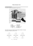
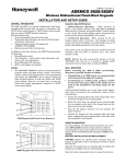
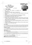
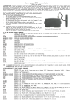
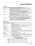
Dear Tech-Man Subscriber:
ADEMCO apologizes for any misunderstanding that has arisen due to our recent
decision to have our technical information removed from the Tech-Man web site. You
may appreciate that one of our key concerns is to provide installing security dealers with
timely and accurate information on our products, and we were concerned about the data
posted to the Tech-Man web site. For obvious reasons, we also do not wish unauthorized
individuals to have access to information on installing and configuring ADEMCO
systems. These concerns were what prompted us to ask Tech-Man to stop posting
ADEMCO installation instructions and user manuals.
Several of you have written us to ask that we reconsider this decision. We have.
We will not require Tech-Man to remove the ADEMCO data. ADEMCO, however, is
not responsible for the operation and maintenance of this site - thus we cannot guarantee
the timeliness or accuracy of the information posted on the Tech-Man web site.
The ADEMCO web site is located at www.ademco.com and contains accurate
timely data about our products. You may request a PIN number for access to the
ADEMCO Technical Support web site and FAXBACK system.
If you need assistance on troubleshooting, or if you have other technical questions
about our products not addressed in the information posted at our web site, please contact
ADEMCO Technical Support at 800-645-7492.
Thank you for understanding.
Sincerely,
Herb Lustig
www.PDF-Zoo.com
www.PDF-Zoo.com
4500 THERMOSTAT
INSTALLATION INSTRUCTIONS
N7970 7/97
www.PDF-Zoo.com
www.PDF-Zoo.com
Table of Contents
Section 1. GENERAL DESCRIPTION ................................................................................1-1
Application and Description..............................................................................1-1
4500 Specifications ............................................................................................1-2
Section 2. Front Panel Controls ........................................................................................2-1
Description .........................................................................................................2-1
Section 3. Installing the 4500 Thermostat........................................................................3-1
General Information ..........................................................................................3-1
Mounting and Installation ................................................................................3-2
Wiring Connections ...........................................................................................3-2
Step-by-Step Installation Instructions .............................................................3-5
Setting the DIP switch ......................................................................................3-8
Setting the Fan Control Pins ............................................................................3-9
Section 4. Programming the 4286 to Add 4500 Thermostat(s) ......................................4-1
General ...............................................................................................................4-1
To Enter and Use the 4286 Programming Mode .............................................4-2
Thermostat Voice Descriptors Vocabulary.......................................................4-9
Section 5. Testing the 4500 With the 4286 .......................................................................5-1
General ...............................................................................................................5-1
Step-by-Step Testing Procedure .......................................................................5-1
Setting the Premises Thermostat .....................................................................5-2
Setting the 4500 Thermostat ............................................................................5-2
Menu Selections .................................................................................................5-3
Section 6. Troubleshooting ...............................................................................................6-1
General ...............................................................................................................6-1
Typical Thermostat Set-up Problems ...............................................................6-1
Section 7. Appendices ...................................................................................................... A-1
FCC (Part 15) Statement.................................................................................. A-1
Ademco Limited Warranty ............................................................................... A-2
Summary of Connections ................................................................................ A-3
ii
www.PDF-Zoo.com
www.PDF-Zoo.com
S E C T I O N
1
General Description
• • • • • • • • • • • • • • • • • • • • • • • • • • • • • • • • • • • • • • • • • •
In This Section
♦ Application and Description
♦ 4500 Specifications
• • • • • • • • • • • • • • • • • • • • • • • • • • • • • • • • • • • • • • • • • •
Application and Description
The Ademco 4500 thermostat provides control for both heat and air
conditioning. The Ademco 4286 Phone Module is required in the
installation for use with the 4500 thermostat. The user sets the 4500
thermostat using any Touch-tone phone, either on premises or remotely. The
4500 is not a replacement for the existing thermostat, which remains in the
installation. The 4500 can be user selected to provide remote control and setback functions.
In summary, the ADEMCO thermostat allows the user to:
•
Set back the temperature (to that set in the ADEMCO thermostat)
automatically by arming in the AWAY mode when leaving home.
•
Resume normal temperature (as set by the existing thermostat)
automatically by disarming the system when returning home.
•
Check the present temperature by phoning in from a remote location.
The Ademco 4500 Thermostat cannot be used on 110 volt control lines. To
prevent a shock or fire hazard, make sure there is only low voltage (typically
24VAC) on all control wiring of the heating and cooling system before starting
the installation. Only qualified personnel shall test the voltage to prevent a
shock hazard.
www.PDF-Zoo.com
www.PDF-Zoo.com
4500 Installation Instructions
4500 Specifications
Operating Range
Temperature Setting Range
Temperature Reading Accuracy
Voltage
Current Draw
Air Conditioner Compressor Off Cycle
Physical Dimensions
Control loop rating (each)
1-2
www.PDF-Zoo.com
www.PDF-Zoo.com
32 to 122 degrees F., 0 to 50 degrees C.
45 to 99 degrees F., 7 to 37 degrees C.
± 2 degrees F., ± 1 degree C.
11 to 14VDC
50 mA
5 minutes minimum
6-3/16” by 2-7/8” by 1-1/4”
24VAC RMS nominal at 500 mA.
S E C T I O N
2
Front Panel Controls
• • • • • • • • • • • • • • • • • • • • • • • • • • • • • • • • • • • • • • • • • •
In This Section
♦ Description
• • • • • • • • • • • • • • • • • • • • • • • • • • • • • • • • • • • • • • • • • •
Description
Referring to Figure 1 below, there are two controls and one status indicator
on the front panel of the thermostat.
HEAT <> COOL BYPASS <> ACTIVE
1
2
3
Figure 1. Front Panel Controls
1 - HEAT/COOL Switch
This switch is used to set the control mode of the 4500 thermostat. The mode
can be set to either heat or cool. This is the same as found on most
thermostats. For premises that only have heat or air conditioning but not
both, the proper mode should be selected with this switch, and the setting
should not be changed.
2 - ACTIVE/BYPASS Switch
This switch is used to select the thermostat that will control the HVAC
system: the premises thermostat or the 4500. When this switch is set to the
ACTIVE mode, the 4500 is enabled and can set-back the premises
temperature when the security system is ARMED AWAY. BYPASS is used
to bypass the 4500 completely and use the pre-existing thermostat at all
times.
www.PDF-Zoo.com
www.PDF-Zoo.com
2-1
4500 Thermostat Installation Instructions
You will not be able to adjust room temperature by phone when the 4500 is
bypassed.
There are several uses for the BYPASS switch function:
• Allows the user to go back to their pre-existing thermostat at any time.
• Allows heating/air conditioning service people to bypass the 4500 during
HVAC servicing and maintenance. The 4500 is out of the HVAC control
circuit when bypassed.
• Allows switching back to the pre-existing thermostat if the security
system is not working or is being serviced.
3 - ACTIVE/BYPASS Indicator
This LED indicates the status of the 4500.
When the ACTIVE/BYPASS switch is in the ACTIVE position, the LED will
be continuously on.
When in BYPASS, the LED will be continuously off.
If the 4500 has lost connection with the 4286 phone module, the LED will flash,
indicating 4500 connections, DIP switch address settings, and 4286 installer
programming entries should be checked.
2-2
www.PDF-Zoo.com
www.PDF-Zoo.com
S E C T I O N
3
Installing the 4500 Thermostat
• • • • • • • • • • • • • • • • • • • • • • • • • • • • • • • • • • • • • • • • • •
In This Section
♦ General
♦ Mounting and Installation
♦ Wiring Connections
♦ Step-by-Step Installation Instructions
♦ Setting the DIP Switch
♦ Setting the Fan Control Pins
• • • • • • • • • • • • • • • • • • • • • • • • • • • • • • • • • • • • • • • • • •
General Information
The 4500 is controlled by a four-wire interface from the 4286 VIP Module and
is powered by 12VDC auxiliary power from the 4286 (which in turn is
powered by the control panel).
The 4500 has separate loops for heat, cool and fan, which connect to the
existing home HVAC system wiring.
There are up to five wires that connect the 4500 to the existing thermostat at
the premises. The user can then switch between the 4500 and the existing
thermostat using the ACTIVE/BYPASS switch previously described.
The 4500 can be used in most applications where ordinary low voltage
thermostats are used. It cannot be used for control of electric heat pumps or
line voltage systems (with 110VAC control lines). Line voltage systems can be
converted to low voltage systems with the addition of a 24 volt transformer
and a relay to control the 110 volt power. These components are available
from home supply stores and other suppliers of heating system components.
Conversion of a 110VAC system to a 24VAC system requires a licensed
electrician.
www.PDF-Zoo.com
www.PDF-Zoo.com
3-1
4500 Thermostat Installation Instructions
While installation of the 4500 is possible without the services of a HVAC
contractor, some installers will prefer to have an HVAC contractor connect
the 4500 to the HVAC system and test its operation. This is recommended if
you do not have HVAC experience. In cases where you prefer to do the entire
installation, it is suggested that the HVAC contractor be contacted for
information on the type of heating system and the amount of “span” (i.e.
temperature swing) that should be set with the 4286 phone module.
Mounting and Installation
The 4500 thermostat is designed to be mounted alongside the existing
thermostat. Once the 4500 is mounted, the wiring connections can be made.
The wires to the existing thermostat will have to be disconnected, and then
re-connected with the 4500 as shown in Figure 3.
Refer to the Wiring Connections section below to understand how the 4500
and existing thermostat are connected.
Wiring Connections
Before you can understand how the 4500 is connected, you should first
understand how the existing thermostat and HVAC system is connected.
These connections are shown in Figure 2 below:
HVAC
System
R
Rc
PREMISES
THERMOSTAT
W Y
G
Heat (W)
Cool (Y)
Fan (G)
Figure 2. HVAC System with Existing Thermostat
As you can see, there are a total of five wires connected between the existing
thermostat and HVAC system.
The first two wires, R and Rc, are used for loop power.
• R powers the heat loop (and sometimes the fan loop).
• Rc powers the cooling loop (and the fan loop).
3-2
www.PDF-Zoo.com
www.PDF-Zoo.com
Section 3. Installing the 4500 Thermostat
Sometimes, R and Rc are jumpered together at the premises thermostat and
are connected to the HVAC system with a single common wire. This is the
case if both heating and air conditioning are controlled by the same control
system.
The remaining three wires connect the thermostat to the heating, cooling and
fan control loop inputs of the HVAC system.
Under the correct circumstances, switches in the thermostat connect the
applicable power connection (R or Rc) to the applicable control loop of the
HVAC system, turning it on. For example, if the thermostat is set to turn the
heat on when 65 degrees is reached, the relay contacts between the power
connection (R) and the wire going to the heating control loop (W) will close
when the temperature drops to 65 degrees. The heating system will be
activated. Figure 3 shows the same system with the 4500 thermostat and
4286 phone module added:
R
4286
PHONE
MODULE
Rc
Rc
4500
THERMOSTAT
HVAC
System
6
OUT
Heat (W)
Cool (Y)
Fan (G)
7
8
5
4
R
PREMISES
THERMOSTAT
3
IN
W Y
G
Heat (W)
Cool (Y)
Fan (G)
Figure 3. 4500 Thermostat with HVAC System
www.PDF-Zoo.com
www.PDF-Zoo.com
3-3
4500 Thermostat Installation Instructions
If you are installing the 4500 in a heat only system, the setup will look like
Figure 4 below.
4286
PHONE
MODULE
R
R
4500
THERMOSTAT
HVAC
System
6
8
5
PREMISES
THERMOSTAT
3
IN
OUT
G
W
Heat (W)
Heat (W)
Fan (G)
Fan (G)
Figure 4. 4500 Thermostat with Heating System Only
Some heating systems, such as the forced-air type, have a fan (connections
are shown). Other heat-only systems may not include a fan, in which case
the fan connections are not used.
If you are installing the 4500 in a cooling only system, the setup will look like
Figure 5 below.
4286
PHONE
MODULE
Rc
Rc
4500
THERMOSTAT
HVAC
System
7
OUT
8
5
PREMISES
THERMOSTAT
4
IN
Y G
Cool (Y)
Cool (Y)
Fan (G)
Fan (G)
Figure 5. 4500 Thermostat with Cooling System Only
3-4
www.PDF-Zoo.com
www.PDF-Zoo.com
Section 3. Installing the 4500 Thermostat
When installing the 4500 thermostat, refer to the Summary of Connections at
the back of this manual. This diagram depicts the 4500's terminal strip and
shows exactly how the thermostat must be wired.
The heating/cooling system and thermostat you are working on may not have
all the connections shown.
All heating systems have R and W connections. Heating systems with a fan
control have the G connection.
Air conditioning systems have Rc and Y connections as well as a G connection
for the fan.
Combination heat and air conditioning systems usually will have all connections
shown. Sometimes R and Rc are common, and are jumpered together at the
premises thermostat. This is the case if both heating and air conditioning are
controlled by the same control system.
Step-by-Step Installation Instructions
To install the 4500 thermostat, follow the procedure below:
1. As should be done when working on any electrical equipment, remove
primary power to the system to prevent damage to the equipment.
2. Open the front panel of the 4500 so that you can access its terminal strip.
3. Mount the 4500 as near to the premises thermostat as possible.
4. Make a note of the terminal number that the Y(ellow), G(reen), and
W(hite) wires are connected to on the existing thermostat. You will need
to connect new wires to these terminals later. Tag and disconnect those
wires from the premises thermostat as follows:
•
White (W) Heat connection
•
Yellow (Y) Cool connection
•
Green (G) Fan connection
These three wires removed come from the HVAC system (refer to Figure 2)
and will be connected to the new 4500 thermostat. It may be necessary to
splice these wires in order to reach the terminals of the 4500.
www.PDF-Zoo.com
www.PDF-Zoo.com
3-5
4500 Thermostat Installation Instructions
5. Connect the tagged wires removed in step 4 from the HVAC system to the
applicable terminals of the 4500. Refer to the following table for proper
connection information.
Table 1
Lead from HVAC
system
Terminal on
4500
Fan (green) (G)
8
Cool (yellow) (Y)
7
Heat (white) (W)
6
6. Connect a wire to each of the vacant terminals on the premises
thermostat that you noted in step 4 above, and make a run from those
terminals to the 4500. Note that HVAC industry standard color codes
and abbreviations are noted here, but these colors may not have been
used in the original installation.
7. Connect the three wires installed in step 6 from the premises thermostat
to the 4500 referring to the following table for proper connection
information.
Table 2
Terminal on existing
thermostat
Terminal on
4500
Fan (G)
5
Cool (Y)
4
Heat (W)
3
8. Verify that the following jumper wires are in place on the 4500 terminal
strip. Replace if missing:
Table 3
3-6
www.PDF-Zoo.com
www.PDF-Zoo.com
From 4500
Terminal
To 4500
Terminal
1
3
2
4
Section 3. Installing the 4500 Thermostat
9. Connect the 4500 to the 4286 phone module using the supplied keypad
type cable. The cable contains four wires of different colors which are
connected to the 4500 as indicated in the following table:
Table 4
Wire from 4286
cable
Terminal on
4500
Green
9
Red
10
Black
11
Yellow
12
If two 4500 thermostats are used, connect them in parallel by running
another set of wires from the first 4500 to the second 4500 using the same
terminals as shown in Table 4 above.
Connections from 4286 Phone Module to 4500 thermostats
4286
PHONE
MODULE
THERMOSTAT PORT
TO 4500
THERMOSTATS
P1
RED
BLACK
GREEN
YELLOW
www.PDF-Zoo.com
NO CONNECTION
P2
www.PDF-Zoo.com
TO CONTROL
PANEL
3-7
4500 Thermostat Installation Instructions
10. Once the 4500 is mounted, you need to set its DIP switch and 3-pin fan
control jumper. These procedures are described below.
Setting the DIP Switch
The 4500 includes a DIP switch for setting the address of the thermostat.
The 4286 phone access module can include up to 2 thermostats per system.
These are referred to as thermostats 1 and 2.
Set thermostat #1 DIP switch to address 01.
If there are 2 thermostats in the system the second must have its DIP switch
set to address 02.
DIP switch set to 01:
DIP switch set to 02:
5 4 3 2 1
5 4 3 2 1
DOWN UP
DOWN UP
If there is only one 4500 thermostat in the system, program the 4286 for
operation with thermostat #1 (see the section “Programming the 4286 to Add
Thermostats”). If there are two thermostats in the system, ask the user which
one will be used the most. The most commonly used thermostat should be
programmed as thermostat #1, since the voice menus allow setting of
thermostat #1 as soon as the thermostat setting menu is entered.
NOTE:
To assist you in setting the DIP Switches, the words
“UP” and “DOWN” are marked on the 4500 thermostat
printed circuit board, as shown here.
The words, “UP” and “DOWN” shown in the diagram of the DIP switches above,
are as marked on the thermostat printed circuit board.
3-8
www.PDF-Zoo.com
www.PDF-Zoo.com
Section 3. Installing the 4500 Thermostat
Setting the Fan Control Pins
The three fan control pins in the center of the 4500 are used to control the
operation of the HVAC system’s fan. Using the jumper provided, you can
select whether or not the system’s fan should turn on with cooling and
heating, or turn on only with cooling. The operation of the fan depends upon
which two pins the jumper is installed on.
If you want the fan to turn on with cooling only, place the jumper provided
between pins 2 and 3.
If you want the fan to turn on for both heating and cooling, place the jumper
between pins 1 and 2.
PLACE THIS JUMPER
ON FAN CONTROL PINS
SHOWN SET TO 01
1 2 3
FAN
CONTROL PINS
JUMPER PLACED ON 1 and 2 = FAN ON WITH HEAT AND COOL
JUMPER PLACED ON 2 and 3 = FAN ON WITH COOL ONLY
After installation has been completed, replace the cover of the 4500
thermostat, reapply primary power to the system and continue
thermostat set-up in Section 4.
Phone announcements during the first minute of application of primary power to
the system or after exiting 4286 installer programming mode will yield
“temperature 00 (zero, zero)” This is perfectly normal. Once the system has
reset itself, correct messages will be annunciated as called for in the
programming of the thermostat.
www.PDF-Zoo.com
www.PDF-Zoo.com
3-9
4500 Thermostat Installation Instructions
3-10
www.PDF-Zoo.com
www.PDF-Zoo.com
S E C T I O N
4
Programming the 4286 to Add
4500 Thermostat(s)
• • • • • • • • • • • • • • • • • • • • • • • • • • • • • • • • • • • • • • • • • •
In This Section
♦ General
♦ To Enter and Use the 4286 Programming Mode
♦ Programming Fields
♦ Step-by-Step Programming Instructions
♦ Thermostat Voice Descriptor Vocabulary
• • • • • • • • • • • • • • • • • • • • • • • • • • • • • • • • • • • • • • • • • •
General
To install the 4286 with 4500 thermostats, you must program the 4286 using
its installer programming mode. This is done using a Touch-tone phone at
the premises that is wired to the 4286 handset terminals.
The 4286 installer-programming mode may be entered within 3 hours from
the time that power is applied to its 12VDC input.
The installer programming mode options allow you to program the 4286 to:
•
Drive 1 or 2 4500 thermostats
•
Set up the system to work in degrees Fahrenheit (F), or degrees
Centigrade (C).
•
Announce room temperature along with security system status reports.
•
Provide voice descriptions for the thermostats such as “upstairs bedroom
temperature.”
•
Select the partition that will trigger a temperature set-back when the
system is ARMED AWAY. This is done by selecting a keypad address
assigned to the desired partition).
www.PDF-Zoo.com
www.PDF-Zoo.com
4-1
4500 Thermostat Installation Instructions
To Enter and Use the 4286 Programming Mode:
1. Pick up a premises touch tone phone connected to the 4286 handset
output.
2. Enter the 2 digit phone code on the phone keypad. If the 4286 is
announcing, wait until system status announcements have been
completed, then press # 98. The 4286 will announce the contents of
programming field 00.
New data may be entered into each field once the field contents are
announced. Once accepted, the new data will be echoed back with an
announcement. If an erroneous entry is detected, a buzzer sound will be
heard in the receiver and the current field and data will be repeated. If
you wish to change the data again, reenter it after the echoed
announcement.
3. Once you are satisfied with a field entry, press ✴ to go on to the next
field. If you want to go back one field, press #. Pressing ✴ after Field 15
will return you to Field 00. Likewise, pressing # at Field 00 will put you
back to Field 15.
If you do not need to program all fields, such as to modify a program
already entered, press ✴ on the phone keypad to advance by one field
each time until desired field number is announced. For example,
pressing ✴ ✴ ✴ will advance the field from 00 to 03.
Programming Fields
The following programming fields need to be programmed as described in
previous steps 1 thru 3.
System default settings are indicated by [default] following an entry.
Field 00: Monitored Keypad Address
This field enables or disables the 4500 thermostat AND speaker output
features and selects which keypad to monitor.
Make an entry based on the following chart:
4-2
www.PDF-Zoo.com
www.PDF-Zoo.com
Section 4. Programming the 4286 to Add Thermostat(s)
If
The System
Contains
Thermostat
Speaker
Addressable
Keypad
NonAddressable
Keypad
Select “MUTE”
(4286 #97 Mode)
01 - 30
31
No
Assign 4500 to
same partition
as keypad
31
Yes
Assign 4500 to
same partition
as keypad
00
00
No
[default]
[default]
(exclude 04)*
Thermostat
01 - 30
No Speaker
(exclude 04)*
No Thermostat
No Speaker
Comments
*Do NOT select 04, which is the address of the 4286 Phone Module.
With no speaker connected, the speaker option must still be disabled. After
exiting the 4286 programming mode, use the # 97 speaker control menu of the
4286 and choose the “MUTE” menu selection. Refer to “Programming
Speaker Output Mode” on page 3-9 of the 4286 Installation Instructions for
more detail.
Field 01: Phone Panic Address
The 4286 will trigger a panic alarm by sending a panic key sequence to the
control panel when a phone panic key sequence is entered on a Touch tone
phone keypad. Refer to the “Basic Operating Guide” in this manual for
details.
To disable the phone panic feature, enter 00 [default] Otherwise:
In a system that uses addressable keypads:
1. Select an unused device address (01-31) to be used to send phone
panics to the control panel. Assign this address to a keypad through
the control panel’s #93 device programming mode (although a
physical keypad will not actually be connected). Do not select 04,
which is the address of the 4286 VIP Module.
2. Enter the same address in this field
In a system that uses non-addressable keypads:
Set this field to 31 to enable phone panics.
www.PDF-Zoo.com
www.PDF-Zoo.com
4-3
4500 Thermostat Installation Instructions
Field 02: Control Panel Type
1 = Vista-10 and Vista-10SE, Via-30P and Via-30PSE, 4140XMP (with voice
upgrade EPROM)
2 = Vista-20, Vista-20HW and Vista-20SE [default]
4 = Vista-40, Vista-50P, Vista-100, and Vista-120.
Field 03: Units of Temperature
0 = temperatures in degrees F. [default]
1 = temperatures in degrees C.
If an existing system has its temperature units changed,
temperature(s) must be reprogrammed to reflect the new values.
set-back
Field 04: Thermostat #1 Enable and Address:
00 = thermostat #1 disabled (not in the system) [default]
01 = set address to 01
Field 05: Thermostat #1 Swing:
digit 1: Swing above set point
digit 2: Swing below set point
digit 1 2
This field defines how many degrees below the set point the heat will turn on,
and how many degrees above the set point the heat will turn off. These
values also define the swing of the air conditioner operation. This option is
also known by HVAC (Heating-Ventilation-Air-Conditioning) installers as
“temperature span” or “hysteresis.” It is recommended that the premises
HVAC installer be consulted to choose the values to be programmed for
optimal HVAC system efficiency.
The following table indicates the proper programming settings for the
adjustment of the thermostat in this field.
4-4
www.PDF-Zoo.com
www.PDF-Zoo.com
Section 4. Programming the 4286 to Add Thermostat(s)
The first digit indicates the swing above the set point; the second digit indicates the swing
below the set point, as indicated below:
Temperature Span (Swing)
“ABOVE
Digit #1
1=
2=
3=
4=
5=
6=
7=
0.0 deg. F. (0.0 deg. C.)
+0.5 deg. F. (0.3 deg. C.)
+0.75 deg. F. (0.4 deg. C.)
+1.0 deg. F. (0.6 deg. C.)
+1.5 deg. F. (0.8 deg. C.)
+2.0 deg. F. (1.1 deg. C.)
+2.5 deg. F. (1.4 deg. C.)
“BELOW”
Digit #2
1=
2=
3=
4=
5=
6=
7=
0.0 deg. F. ( 0.0 deg. C.)
-0.5 deg. F. (-0.3 deg. C.)
-0.75 deg. F. (-0.4 deg. C.)
-1.0 deg. F. (-0.6 deg. C.)
-1.5 deg. F. (-0.8 deg. C)
-2.0 deg. F. (-1.1 deg. C)
-2.5 deg. F. (-1.4 deg. C.)
NOTE: DO NOT SELECT 1,1
The following are suggested entries for digits one and two respectively in
Field 05 for different types of heating systems:
1,4 = Hot water heat [default]
4,1 = Hot air or electric heat
6,4 = Gravity feed systems.
Ask the homeowner or HVAC installer about the type of system at the
premises.
Field 06: Announce Thermostat #1 Temperature
0 = Do not announce thermostat #1 temperature. [default]
1 = Announce thermostat #1 temperature as part of the 4286 status report for
the security system.*
*It is recommended that this field be programmed to enable announcement of
ambient temperature so that premises temperature can be monitored when
user is away.
www.PDF-Zoo.com
www.PDF-Zoo.com
4-5
4500 Thermostat Installation Instructions
For Fields 07-09, select the 3-digit word codes from Table 5 for each descriptor.
If you want less than a 3-word description for the thermostat, set unused
descriptors to 0 0 0.
Note: Fields 07 through 09 select a voice announcement to be associated with
thermostat #1.
For example, if you wanted a voice announcement for “south bedroom
temperature,” you would program Field 07 as 155; Field 08 as 015; and Field
09 as 158.
If you only wanted a voice announcement for “bedroom temperature” you
would program Field 07 as 000; Field 08 as 015; and Field 09 as 158.
Field 07: Thermostat #1 Descriptor #1
default value: 0 0 0 = no announcement [default]
Field 08: Thermostat #1 Descriptor #2
default value: 0 0 0 = no announcement [default]
Field 09: Thermostat #1 Descriptor #3
default value: 0 0 0 = no announcement [default]
Field 10: Thermostat #2 Enable and Address:
00 = thermostat #2 disabled (not in the system) [default]
02 = set address to 02
Field 11: Thermostat #2 Swing
digit 1: Swing above set point
digit 1 2
digit 2: Swing below set point
This field defines how many degrees below the set point the heat will turn on,
and how many degrees above the set point the heat will turn off. These values
also define the swing of the air conditioner operation. This option is also
known by HVAC (Heating-Ventilation-Air-Conditioning) installers as
“temperature span” or “hysteresis.” It is recommended that the premises
HVAC installer be consulted to choose the values to be programmed for
optimal HVAC system efficiency.
4-6
www.PDF-Zoo.com
www.PDF-Zoo.com
Section 4. Programming the 4286 to Add Thermostat(s)
The first digit indicates the swing above the set point; the second digit
indicates the swing below the set point, as indicated below:
Temperature Span (Swing)
“ABOVE
Digit #1
1=
2=
3=
4=
5=
6=
7=
0.0 deg. F. (0.0 deg. C.)
+0.5 deg. F. (0.3 deg. C.)
+0.75 deg. F. (0.4 deg. C.)
+1.0 deg. F. (0.6 deg. C.)
+1.5 deg. F. (0.8 deg. C.)
+2.0 deg. F. (1.1 deg. C.)
+2.5 deg. F. (1.4 deg. C.)
“BELOW”
Digit #2
1=
2=
3=
4=
5=
6=
7=
0.0 deg. F. ( 0.0 deg. C.)
-0.5 deg. F. (-0.3 deg. C.)
-0.75 deg. F. (-0.4 deg. C.)
-1.0 deg. F. (-0.6 deg. C.)
-1.5 deg. F. (-0.8 deg. C)
-2.0 deg. F. (-1.1 deg. C)
-2.5 deg. F. (-1.4 deg. C.)
NOTE: DO NOT SELECT 1,1
The following are suggested entries for digits one and two respectively in
Field 11 for different types of heating systems:
1,4 = Hot water heat [default]
4,1 = Hot air or electric heat
6,4 = Gravity feed systems.
Ask the homeowner or HVAC installer about the type of system at the
premises.
Field 12: Announce Thermostat #2 Temperature
1 = Announce thermostat #2 temperature as part of the 4286 status
report for the security system.*
0 = Do not announce thermostat #2 temperature. [default]
*If a second 4500 thermostat is installed it is recommended that this field be
programmed to enable announcement of ambient temperature so that
premises temperature can be monitored when user is away.
www.PDF-Zoo.com
www.PDF-Zoo.com
4-7
4500 Thermostat Installation Instructions
For Fields 13-15, select the 3-digit word codes from Table 5 for each descriptor.
If you want less than a 3-word description for the thermostat, set unused
descriptors to 0 0 0.
Note: Fields 13 thru 15 select a voice announcement to be associated with
thermostat #2.
For example, if you wanted a voice announcement for “central hall
temperature,” you would program Field 13 as 089; Field 14 as 050; and Field
15 as 158.
If you only wanted a voice announcement for “hall temperature” you would
program Field 13 as 000; Field 14 as 050; and Field 15 as 158.
Field 13: Thermostat #2 Descriptor #1
Default value: 0 0 0 = no announcement [default]
Field 14: Thermostat #2 Descriptor #2
Default value: 0 0 0 = no announcement [default]
Field 15: Thermostat #2 Descriptor #3
Default value: 0 0 0 = no announcement [default]
This completes the programming of the 4500. Once all necessary
fields have been programmed, hang up the phone.
If you want to reenter the 4286 Programming Mode after exiting, you will have
15 minutes to do so using the procedure beginning on page 4-2 of this manual.
The 15 minute time limit is to prevent the user from accidentally entering
programming mode. If more than 15 minutes have passed, you must reset the
system by removing the 12VDC power temporarily from the 4286 by
disconnecting the keyed header that connects it to the control panel (located
near the 2 relays). Wait at least 5 seconds, then reconnect the keyed header
and follow the procedure To Enter and Use the 4286 Programming Mode on
page 4-2 of this manual.
4-8
www.PDF-Zoo.com
www.PDF-Zoo.com
Section 4. Programming the 4286 to Add Thermostat(s)
THERMOSTAT VOICE DESCRIPTORS VOCABULARY
(4286 Phone Access Module Only)
The following three digit codes are used to program thermostat descriptors into the 4286
programming fields 07 thru 09 and fields 13 thru 15.
Table 5
WORD
INDEX
WORD
WORD
INDEX
WORD
WORD
INDEX
WORD
116
255
067
117
161
118
119
AIR
ALARM
AND
APARTMENT
APPLIANCE
AREA
ATTIC
184
130
131
DOWNSTAIRS
DRIVEWAY
DUCT
014
212
145
MEDICAL
MOTHER'S
MOTION
132
133
004
EAST
EQUIPMENT
EXIT
165
146
012
NO
NORTH
NOT
120
121
122
021
051
053
092
015
123
124
162
125
039
BABY
BACK
BAR
BASEMENT
BATHROOM
BATTERY
BED
BEDROOM
BLOWER
BOILER
BRIGHT
BUILDING
BURGLARY
134
211
135
040
029
137
087
FACTORY
FATHER'S
FENCE
FIRE
FLOOR
FOYER
FRONT
011
147
058
148
210
OFF
OFFICE
ON
OPEN
OUTSIDE
013
090
149
061
063
166
PANIC
PARTITION
PATIO
PHONE
POWER
PUMP*
088
028
018
REAR
RIGHT
ROOM
007
150
151
152
153
024
223
155
006
156
157
'S
SERVICE
SHED
SHOP
SIDE
SMOKE
SON'S
SOUTH
STAIRS
STATION
STORAGE
009
089
054
126
127
CALL
CENTRAL
CHIME
CLOSED
COMPUTER
208
052
128
060
163
031
016
008
DAUGHTER'S
DEN
DETECTOR
DEVICE
DIM
DINING
DOOR
DOWN
www.PDF-Zoo.com
www.PDF-Zoo.com
023
138
139
GARAGE
GAS
GLASS
050
010
HALL
HEAT
209
INSIDE
022
KITCHEN
140
027
141
019
030
142
094
143
144
LAUNDRY
LEFT
LIBRARY
LIGHT
LIVING
LOADING
LOWER
MACHINE
MASTER
WORD
INDEX
WORD
156
157
154
062
STATION
STORAGE
SUN
SYSTEM*
158
213
TEMPERATURE
TOOL
025
187
183
185
UP
UPPER
UPSTAIRS
UTILITY
215
017
216
WEST
WINDOW
WING
002
ZONE
069
070
136
071
056
072
159
073
217
074
218
075
219
076
220
077
221
078
222
0
1
1st
2
2nd
3
3rd
4
4th
5
5th
6
6th
7
7th
8
8th
9
9th
4-9
4500 Thermostat Installation Instructions
4-10
www.PDF-Zoo.com
www.PDF-Zoo.com
S E C T I O N
5
Testing the 4500 With the 4286
• • • • • • • • • • • • • • • • • • • • • • • • • • • • • • • • • • • • • • • • • •
In This Section
♦ General
♦ Step-by-Step Testing Procedure
♦ Setting the Premises thermostat
♦ Setting the 4500 Thermostat
♦ Menu Selections
• • • • • • • • • • • • • • • • • • • • • • • • • • • • • • • • • • • • • • • • • •
General
Once the 4500 has been installed, and the 4286 programmed, the system may
be tested with the following procedure.
Step-by-Step Testing Procedure
Perform the steps that follow in order:
1. Bypass all interior zones and any others that may cause an alarm while
the security system is armed in the away state.
2. Arm the security system to the ARMED AWAY state. You are about to
perform a test of the 4500 thermostat set-back operation.
3. If the 4500 will control a heating system, set the 4500 front panel slide
switches to ACTIVE and HEAT. Set the premises thermostat into its
heat mode as well. If only air conditioning will be controlled, skip to
step 6.
4. Perform the following test: Set the set points according to the steps
described in “Setting the Premises and 4500 Thermostat” sections that
follow. Set the premises thermostat 10 degrees higher than room
temperature. Set the 4500 set point to a temperature 5 degrees lower
than the room temperature. The heat should turn off within one minute.
Set the 4500 set point to a temperature 5 degrees higher than room
temperature. The heat should turn on within one minute.
www.PDF-Zoo.com
www.PDF-Zoo.com
5-1
4500 Thermostat Installation Instructions
5. Check the heat mode operation of the premises thermostat by varying its
set point and verifying that the heating system turns on and off.
6. If the 4500 thermostat will control an air conditioning system, set the
4500 front panel slide switches to ACTIVE and COOL. Set the premises
thermostat into its cool mode as well. If only heating will be controlled,
skip to step 9.
7. Set the premises thermostat 10 degrees below the present room
temperature. Similar to step 4 above, turn the air conditioner off and
then on varying the 4500 set point 5 degrees above and below room
temperature. Note that it takes at least five minutes for the air
conditioner to turn on from the time it turns off. This feature is present
in the 4500 to protect the air conditioner compressor from excessive
cycling.
8. Switch the ACTIVE/BYPASS slide switch to BYPASS. Check the cool
mode of the premises thermostat by turning the air conditioner on and off
by varying its set point above and below ambient temperature.
9. If there are two 4500’s in the system, test the operation of the second
4500 by repeating the testing steps 1-8 above. The LOG ON thermostat
setting menu selection (2 key) is used to choose the second thermostat so
it can be set. After testing the 4500’s and premises thermostats, set them
to temperatures as desired by the homeowner.
Setting the Premises Thermostat
The 4500 can decrease the amount of heat or air conditioning that would be
provided by the premises thermostat, but cannot increase it. The premises
thermostat should always be set to a higher heat set point and a lower cool
set point than the 4500 set-back temperature. Then the 4500 will be able to
set-back the temperature, and it will adjust room temperature to the set-back
level when the security system is armed away. If the premises thermostat is
set to provide less heat or air conditioning than the 4500 set-back
temperature, the 4500 will remain passive at all times and the premises
thermostat settings will prevail.
Setting the 4500 Thermostat
To enter and use the 4286 thermostat programming mode:
1. There must be at least one thermostat programmed into the system by
way of the 4286 installer programming mode entry.
5-2
www.PDF-Zoo.com
www.PDF-Zoo.com
Section 5. Testing the 4500 With the 4286 Phone Module
2. Obtain phone access from the phone module. Enter the 2-digit phone
code. Enter the 4-digit system code if prompted.
3. Press # 99 on the phone keypad after the complete status announcement.
4. The 4286 will announce: “Thermostat Mode.”
The temperature setting for thermostat #1 will follow. You can change its set
point using menu selection 1 below. If thermostat #1 is in BYPASS or
CHECK, that status will be announced instead of the set point. The 4286 will
also announce whether set-back has been turned off by the user.
Menu Selections
“To change temperature, enter 1.” This selection is used to set the armed
away set-back temperature for thermostats #1 or #2 (This menu selection
will NOT be announced if the thermostat is in “CHECK or BYPASSED”)
•
To allow the user to change the ARMED AWAY set-back temperature
settings, the 4286 will announce the present setting in effect, and wait for
a new 2-digit temperature setting to be entered. If the current
temperature setting is acceptable to the user, the user may press the ✴
key to advance without changing the setting.
•
If the number entered is outside the allowed range (45° to 99° F., 07° to
37° C), a buzzer will sound from the phone, and the temperature setting
repeated. This will continue until the number entered is within the
allowable range.
•
If the 4500 is BYPASSed, the user must switch the ACTIVE/BYPASS
slide switch on the 4500 front panel to the ACTIVE position, which will
then allow access through the 4286 thermostat menus.
www.PDF-Zoo.com
www.PDF-Zoo.com
5-3
4500 Thermostat Installation Instructions
“For set-back on/off, enter 3.” Turning off set-back will result in it
remaining disabled while armed away, until the next time the system is
disarmed.
This feature allows the user to turn off the set-back before returning home, so
that the premises will have time to return to a comfortable at-home
temperature. It also allows the user to turn off set-back before leaving home,
when they plan to be away only a short time. The user can also turn the setback on again with this menu selection if they have a change of plans.
“To log on, enter 2.” (This selection is announced if more than one
thermostat has been programmed into the system). It allows the user to select
thermostat #1 or #2 for setting. The user can set the 4500 just selected with
the “to change temperature, enter 1” menu selection.
“To exit, enter 0.” (This selection exits the thermostat mode).
If a 4500 thermostat does not respond to the 4286 phone module for two
minutes, the phone module will announce, “Check thermostat (1/2).
(Descriptor),” instead of the temperature.
If the temperature falls below 37° F (3° C), the 4286 phone module will
announce, “Check thermostat (1/2). (Descriptor),” instead of the
temperature.
5-4
www.PDF-Zoo.com
www.PDF-Zoo.com
S E C T I O N
6
Troubleshooting
• • • • • • • • • • • • • • • • • • • • • • • • • • • • • • • • • • • • • • • • • •
In This Section
♦ General
♦ Troubleshooting Typical Thermostat Set-Up Problems
• • • • • • • • • • • • • • • • • • • • • • • • • • • • • • • • • • • • • • • • • •
General
Following the procedures in the 4286 Installation Instructions manual should
result in a minimum number of system problems. If you experience problems
that relate to the use of the 4500 thermostat(s), first check the possible
resolution of some typical thermostat problems that follow.
Thermostat is in check (4286 announces “Check Thermostat,” or the yellow
light is flashing on the 4500):
1. Check that the DIP switch on each thermostat is properly set, and that
the 4500 addresses have been properly programmed in the 4286
programming mode.
2. Check the connections from the 4286 to the 4500, and make sure that the
cable connecting the 4500s to the 4286 faces the correct direction (yellow
toward the corner of the 4286 board).
Heat is cycling on and off too often.
1. Increase the amount of “span” as described in the section “Programming
the 4286 to add 4500 thermostats” in Section 4 of this manual.
2. Make sure that the location where the 4500 is mounted is free of drafts.
Temperature in the room swings too widely when the 4500 is set to
“ACTIVE” mode.
1. Decrease the amount of span as described in the section “Programming
the 4286 to add 4500 thermostats” in Section 4 of this manual.
www.PDF-Zoo.com
www.PDF-Zoo.com
6-1
4500 Thermostat Installation Instructions
4500 or premises thermostat fails to control the HVAC system.
1. Check set points in 4500 and premises thermostat to ensure they are set
properly.
2. If BYPASS of 4500 via its front panel switch causes existing thermostat
to work properly, then problem is in the 4500 wiring or within the 4500
itself. If the existing thermostat does not work, check its wiring and
battery, if any.
3. Check wiring connections. Refer to Summary of Connections diagram.
Heating and cooling set point does not change according to settings when
the system is armed or disarmed.
1. Verify temperature settings with the # 99 thermostat mode and that setback is programmed on.
2. Verify the entry for “control panel type” (field 02) using the 4286 phone
programming mode.
3. If the control panel uses non-addressable keypads, verify that the
“monitored keypad address” (set in phone programming mode, Field
01) is set to 31.
4. If the control panel uses addressable keypads, verify that the
“monitored keypad address” (set in 4286 phone programming mode
field 01):
a) Matches a control panel “device address” assigned to a keypad,
and
b) Is assigned to the partition where the 4500 thermostat is
physically located.
6-2
www.PDF-Zoo.com
www.PDF-Zoo.com
S E C T I O N
7
Appendices
• • • • • • • • • • • • • • • • • • • • • • • • • • • • • • • • • • • • • • • • • •
In This Section
♦ Federal Communications Commission (FCC) Part 15 Statement
♦ Ademco Limited Warranty
♦ Summary of Connections
• • • • • • • • • • • • • • • • • • • • • • • • • • • • • • • • • • • • • • • • • •
FEDERAL COMMUNICATIONS COMMISSION (FCC)
PART 15 STATEMENT
This equipment has been tested to FCC requirements and has been found acceptable for
use. The FCC requires the following statement for your information:
This equipment generates and uses radio frequency energy and if not installed and used
properly, that is, in strict accordance with the manufacturer's instructions, may cause
interference to radio and television reception. It has been type tested and found to comply
with the limits for a Class B computing device in accordance with the specifications in
Part 15 of FCC Rules, which are designed to provide reasonable protection against such
interference in a residential installation.
However, there is no guarantee that
interference will not occur in a particular installation. If this equipment does cause
interference to radio or television reception, which can be determined by turning the
equipment off and on, the user is encouraged to try to correct the interference by one or
more of the following measures:
• If using an indoor antenna, have a quality outdoor antenna installed.
• Reorient the receiving antenna until interference is reduced or eliminated.
• Move the receiver away from the security control.
• Move the antenna leads away from any wire runs to the security control.
• Plug the security control into a different outlet so that it and the receiver are on
different branch circuits.
• If necessary, the user should consult the dealer or an experienced radio/television
technician for additional suggestions.
The user or installer may find the following booklet prepared by the Federal
Communications Commission helpful: “Interference Handbook”. This booklet is available
from the U.S. Government Printing Office, Washington, DC 20402.
The user shall not make any changes or modifications to the equipment unless authorized
by the Installation Instructions or User's Manual. Unauthorized changes or modifications
could void the user's authority to operate the equipment.
www.PDF-Zoo.com
www.PDF-Zoo.com
A-1
4500 Thermostat Installation Instructions
ADEMCO Limited Warranty
Alarm Device Manufacturing Company, a Division of Pittway Corporation, and its divisions,
subsidiaries and affiliates (“Seller”), 165 Eileen Way, Syosset, New York 11791, warrants its
products to be in conformance with its own plans and specifications and to be free from
defects in materials and workmanship under normal use and service for 24 months from the
date stamp control on the product or, for products not having an Ademco date stamp, for 12
months from date of original purchase unless the installation instructions or catalog sets
forth a shorter period, in which case the shorter period shall apply. Seller's obligation shall
be limited to repairing or replacing, at its option, free of charge for materials or labor, any
product which is proved not in compliance with Seller's specifications or proves defective in
materials or workmanship under normal use and service. Seller shall have no obligation
under this Limited Warranty or otherwise if the product is altered or improperly repaired or
serviced by anyone other than Ademco factory service. For warranty service, return product
transportation prepaid, to Ademco Factory Service, 165 Eileen Way, Syosset, New York
11791.
THERE ARE NO WARRANTIES, EXPRESS OR IMPLIED, OF MERCHANTABILITY, OR
FITNESS FOR A PARTICULAR PURPOSE OR OTHERWISE, WHICH EXTEND BEYOND THE
DESCRIPTION ON THE FACE HEREOF. IN NO CASE SHALL SELLER BE LIABLE TO
ANYONE FOR ANY CONSEQUENTIAL OR INCIDENTAL DAMAGES FOR BREACH OF THIS
OR ANY OTHER WARRANTY, EXPRESS OR IMPLIED, OR UPON ANY OTHER BASIS OF
LIABILITY WHATSOEVER, EVEN IF THE LOSS OR DAMAGE IS CAUSED BY THE SELLER'S
OWN NEGLIGENCE OR FAULT.
Seller does not represent that the products it sells may not be compromised or circumvented;
that the products will prevent any personal injury or property loss by burglary, robbery, fire
or otherwise; or that the products will in all cases provide adequate warning or protection.
Customer understands that a properly installed and maintained alarm may only reduce the
risk of a burglary, robbery, fire or other events occurring without providing an alarm, but it
is not insurance or a guarantee that such will not occur or that there will be no personal
injury or property loss as a result. CONSEQUENTLY, SELLER SHALL HAVE NO LIABILITY
FOR ANY PERSONAL INJURY, PROPERTY DAMAGE OR OTHER LOSS BASED ON A CLAIM
THE PRODUCT FAILED TO GIVE WARNING. However, if Seller is held liable, whether
directly or indirectly, for any loss or damage arising under this Limited Warranty or
otherwise, regardless of cause or origin, Seller's maximum liability shall not in any case
exceed the purchase price of the product, which shall be the complete and exclusive remedy
against Seller. This warranty replaces any previous warranties and is the only warranty
made by Seller on this product. No increase or alteration, written or verbal, of the obligations
of this Limited Warranty is authorized.
A-2
www.PDF-Zoo.com
www.PDF-Zoo.com
Appendices
Heat
Fan
}
TO PREMISES
THERMOSTAT
Cool
Fan
Cool
Red
Black
Yellow
}
TO 4286
VOICE MODULE
54321
1
2
3
4
5
6
7
8
9 10 1 1 1 2
}
DOWN UP
TO HVAC
SYSTEM
Green
Heat
Two jumper wires are factory installed
between screw terminals 1-3 and 2-4.
Replace if missing.
DIP
SWITCH
}
SHOWN SET
TO 01
1 2 3
FAN
CONTROL PINS
TEMPERATURE
SENSOR
JUMPER PLACED ON 1 and 2 = FAN ON WITH HEAT AND COOL
JUMPER PLACED ON 2 and 3 = FAN ON WITH COOL ONLY
4500 Thermostat Summary of Connections
.
www.PDF-Zoo.com
www.PDF-Zoo.com
A-3
165 Eileen Way, Syosset, New York, 11791
Copyright © 1997 PITTWAY CORPORATION
N7970 7/97
www.PDF-Zoo.com
www.PDF-Zoo.com