1
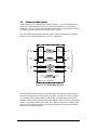
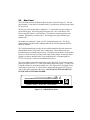
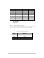
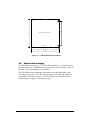
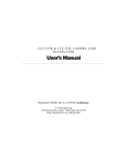
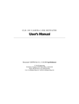
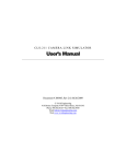
CLB-501B CAMERA LINK BREAKOUT BOX User’s Manual Document # 201107, Rev 0.2, 3/23/2012 preliminary Vivid Engineering 159 Memorial Drive, Suite F • Shrewsbury, MA 01545 Phone 508.842.0165 • Fax 508.842.8930 www.vividengineering.com • [email protected] Table of Contents 1. Introduction 1 1.1. Overview 1 1.2. Features 2 1.3. Functional Description 3 1.3.1. Breakout Header Pixel Assignments 5 1.4. Typical Application 11 1.5. Specifications 12 2. Interface 13 2.1. Front Panel 13 2.1.1. Video Connectors 14 2.1.2. Cable Shield Grounding 14 2.2. Rear Panel 15 2.2.1. Breakout Header Signals 16 2.2.2. Auxiliary Header Signals 17 3. Mechanical 18 3.1. Dimensions 18 3.2. External Power Supply 19 4. Revision History 20 1. Introduction 1.1. Overview The CLB-501B Camera Link1 Breakout Box provides convenient access to the data transferred between camera and frame grabber over a Camera Link connection. All video, control, and communication data can be monitored and/or sourced via a standard header connector located on the rear panel. CLB-501B incorporates high-speed 85MHz interfaces and is compatible with all Camera Link “base” configuration cameras. “Medium” configuration applications are supported using two CLB-501B’s. Features include a camera signal detect indicator and isolated DC power input The CLB-501B Camera Link Breakout Box is housed in sturdy, compact aluminum enclosures. A locking-plug power supply is optional. Vivid Engineering Camera Link Breakout Box CLB-501B LINK PWR CAMERA FRAME GRABBER 1 The Camera Link interface standard enables the interoperability of cameras and frame grabbers, regardless of vendor. The Automated Imaging Association (AIA) sponsors the Camera Link program including the oversight Camera Link Committee, the self-certification program, and the product registry. The Camera Link specification may be downloaded from the AIA website, found at www.machinevisiononline.org Camera Link is a trademark of the Automated Imaging Association 1 1.2. Features • Provides access to all data (video, camera control, serial comm.) • Standard 0.1” pitch dual-row header-style breakout connector • Removable header jumpers (shunts) enable external data sourcing • Standard LVTTL signal levels • Power, ground, and buffered clock pins aide interfacing • Uses standard Camera Link cables (not included) • Supports Camera Link “base” configuration • High-speed 85 MHz interface chipset, works with any base camera • “Medium” configuration support using two CLB-501Bs • Also acts as a repeater, doubling max distance between camera and frame grabber • Link indicator • Isolated DC power input • Minimal data pass-through latency • Sturdy, compact aluminum enclosure w/ mounting flange • Multi-nation power supply included, locking-plug power supply optional • 3-year warrantee 2 1.3. Functional Description A block diagram of the CLB-501B is provided in Figure 1-1. The CLB-501B provides access to the data transferred between camera and frame grabber over a Camera Link connection. All video, control, and communication data can be monitored and/or sourced via a header-style breakout connector located on the rear panel. Video Data Channel Link Receiver Rear-Panel Header Channel Link Transmitter Video Data Camera Control LVDS Transmitter Rear-Panel Header LVDS Receiver Camera Control LVDS Rcvr Rear-Panel Header LVDS Xmtr LVDS Xmtr Rear-Panel Header LVDS Rcvr Serial Comm Link buffered pixel clock Rear-Panel Header Serial Comm Link To Camera Link Frame Grabber To Camera Link Camera The CLB-501B incorporates the connectors, signals, pinouts, and chipset in compliance with the Camera Link specification for the “base” configuration. +3.3 vdc ground CLB-501B Camera Link Breakout Box Figure 1-1: CLB-501B Block Diagram The CLB-501B breakout connector is a standard dual-row header for easy connection to external test equipment and is located on the rear panel. The unit comes with a complete set of shorting blocks (shunts) installed on the header. The shunts may be removed to break the connection between camera and frame grabber in order to insert an external data source (i.e. for camera control, serial comm., etc.). Since all video data is available at the header, the CLB-501B may also be used to remap/realign video and control information between camera and frame grabber. 3 To aide in interfacing to external equipment, the CLB-501B incorporates and auxiliary header that provides 3.3VDC power, ground, and a buffered version of the pixel clock. The buffered clock enables access to the reference clock without the risk of degradation of the raw clock signal which could cause a malfunction. The raw (unbuffered) pixel clock is also available on the header, but care should be taken in its use. The buffered clock is sourced from the output (frame grabber) side of the breakout header. All signals on the header utilize standard LVTTL levels. Care must be taken when interfacing to the header to avoid damage to the internal components. The CLB-501B incorporates high-speed (85MHz) interfaces and is compatible with any “base” configuration camera. “Medium” configuration applications are supported using two CLB-501B’s in parallel. The CLB-501B does not support the Camera Link “full” configuration. The latency (i.e. delay) of the video, control, and communication signals passing through the CLB-501B is minimal. This is an important criteria in time-critical applications. See Table 1.1 for the latency specifications. CLB-501B also acts as a repeater and doubles the maximum separation between the camera and the frame grabbers. A front-panel link status indicator illuminates when the camera video signal is detected. The front panel also includes a power indicator. The CLB-501B is powered by an external wall plug-in power supply. A multi-nation power supply is standard. Optionally, the CLB-501B is available with a locking-plug power supply. The locking plug reduces the risk of accidental disconnection from the rear-panel power jack. The CLB-501B is also available without power supply. The CLB-501B DC power input is electrically isolated from the internal circuitry. This feature ensures compatibility with user power systems. 4 1.3.1. Breakout Header Pixel Assignments Tables 1-1 through 1-6 identify the assignment of camera pixel data to the breakout header pins for the Camera Link “base” configuration modes. Table 1-1: Pixel Assignment, 8-bit x 1~3 Modes Camera Link Pixel Assignment CLB-501B Breakout Pin A0 D0 A1 D1 A2 D2 A3 D3 A4 D4 A5 D6 A6 D27 A7 D5 B0 D7 B1 D8 B2 D9 B3 D12 B4 D13 B5 D14 B6 D10 B7 D11 C0 D15 C1 D18 C2 D19 C3 D20 C4 D21 C5 D22 C6 D16 C7 D17 5 Table 1-2: Pixel Assignment, 10-bit x 1~2 Modes Camera Link Pixel Assignment CLB-501B Breakout Pin A0 D0 A1 D1 A2 D2 A3 D3 A4 D4 A5 D6 A6 D27 A7 D5 A8 D7 A9 D8 B0 D15 B1 D18 B2 D19 B3 D20 B4 D21 B5 D22 B6 D16 B7 D17 B8 D13 B9 D14 6 Table 1-3: Pixel Assignment, 12-bit x 1~2 Modes Camera Link Pixel Assignment CLB-501B Breakout Pin A0 D0 A1 D1 A2 D2 A3 D3 A4 D4 A5 D6 A6 D27 A7 D5 A8 D7 A9 D8 A10 D9 A11 D12 B0 D15 B1 D18 B2 D19 B3 D20 B4 D21 B5 D22 B6 D16 B7 D17 B8 D13 B9 D14 B10 D10 B11 D11 7 Table 1-4: Pixel Assignment, 14-bit x 1 Mode Camera Link Pixel Assignment CLB-501B Breakout Pin A0 D0 A1 D1 A2 D2 A3 D3 A4 D4 A5 D6 A6 D27 A7 D5 A8 D7 A9 D8 A10 D9 A11 D12 A12 D13 A13 D14 8 Table 1-5: Pixel Assignment, 16-bit x 1 Mode Camera Link Pixel Assignment CLB-501B Breakout Pin A0 D0 A1 D1 A2 D2 A3 D3 A4 D4 A5 D6 A6 D27 A7 D5 A8 D7 A9 D8 A10 D9 A11 D12 A12 D13 A13 D14 A14 D10 A15 D11 9 Table 1-6: Pixel Assignment, 24-bit RGB Mode Camera Link Pixel Assignment CLB-501B Breakout Pin R0 D0 R1 D1 R2 D2 R3 D3 R4 D4 R5 D6 R6 D27 R7 D5 G0 D7 G1 D8 G2 D9 G3 D12 G4 D13 G5 D14 G6 D10 G7 D11 B0 D15 B1 D18 B2 D19 B3 D20 B4 D21 B5 D22 B6 D16 B7 D17 10 1.4. Typical Application A typical CLB-501B application is shown in Figure 1-2. A Camera Link “base” configuration camera is connected to the CLB-501B via a standard Camera Link cable. A second cable is then connected from the CLB-501B to a Camera Link frame grabber. External test equipment, signal sources, etc may then be connected via the rear panel breakout header to monitor and/or source the desired Camera Link interface signals. To “monitor” signals the shorting blocks (shunts) are installed on the breakout header, allowing data to transfer between camera and frame grabber. The header posts are doubleheight, allowing connection to external equipment even when the shunts are present. To “source” signals (i.e. serial comm, camera control, etc), the corresponding shunt is removed to isolate the desired signal(s). The external signal source is then connected on the appropriate side (“to camera” or “to frame grabber”) of the breakout header connector. CLB-501B Camera Link Breakout Box Test Equipment Signal Sources Vivid Engineering Camera Link Breakout Box CLB-501B LINK PWR CAMERA Camera Link Camera FRAME GRABBER Standard Camera Link Cables Figure 1-2: CLB-501B Application 11 Camera Link Frame Grabber 1.5. Specifications Table 1-7: CLB-501B Specifications Feature Specification Video Interfaces Camera Link “base” configuration Video Connectors 26-pin MDR type Breakout Connector 70-pin dual-row 0.1” pitch header w/ removable shunts Auxiliary Connector 4-pin dual-row 0.1” pitch header Frequency Range 20 - 85 MHz Latency Video path: 3 camera pixel clock cycles Control & communication: 5ns max Power Supply Universal wall style w/ outlet plug set Power Plug 2.1 x 5.5 mm, center-positive. Locking style optional. Power Requirements 4.5 – 9 VDC, internally isolated 230 mA @ 5 VDC (typical) Cabinet Dimensions 5.28” (L) x 1.18” (H) 5.12” (D) Weight 11 oz Operating Temperature Range 0 to 50° C Storage Temperature Range -25 to 75° C Relative Humidity 0 to 90%, non-condensing 12 2. Interface 2.1. Front Panel The CLB-501B Camera Link Breakout Box front panel is shown in Figure 2-1. The front panel contains two 26-pin MDR video connectors; one for connecting to the camera and one for connecting to the frame grabber. The front panel also incorporates LED power and link status indicators. Vivid Engineering Camera Link Breakout Box LINK PWR CAMERA FRAME GRABBER Figure 2-1: CLB-501B Front Panel 13 CLB-501B 2.1.1. Video Connectors The MDR-26 video connectors and signal assignments comply with the Camera Link “base” configuration. The camera connector signal assignments correspond to the frame grabber interface defined in the Camera Link Specification. Conversely, the frame grabber connector assignments are as defined for the camera interface in the Camera Link Specification. This arrangement provides compatibility with standard Camera Link cables. 2.1.2. Cable Shield Grounding Camera and frame grabber cable “outer” shields are connected to the CLB-501B aluminum case. Case and endplate contacting surfaces are unpainted, providing a Faraday cage to shield internal circuitry. The case is isolated from the CLB-501B circuitry and the cable “inner” shields, avoiding possible safety concerns. The camera and frame grabber cable “inner” shields connect to circuit digital ground, maintaining signal reference levels between the camera and the CLB-501B, and between the CLB-501B and the frame grabber. 14 2.2. Rear Panel The CLB-501B Camera Link Breakout Box rear panel is shown in Figure 2-3. The rear panel contains a 70-pin dual-row breakout header, a 4-pin dual-row auxiliary header, and a DC power jack. The DC power jack accepts either a standard 2.1 x 5.5 mm barrel-style power plug or a special locking plug. The locking plug has bayonet-style “ears” on the barrel. Once inserted, the plug is turned ¼ turn clockwise. This locks the connection and provides retention. Plug polarity is center-positive. The locking power plug is Philmore part number 2150. The headers are standard 0.1” pitch w/ 0.025” gold-plated square posts. The 70-pin breakout header is double-height, enabling connection to external equipment while the shunts are installed. The 70-pin breakout header provides access to all data transferred between camera and frame grabber for the Camera Link “base” configuration. The breakout header also incorporates the raw (unbuffered) pixel clock. A buffered version which is recommended for use as a clock reference is provided on the 4-pin auxiliary header. Removable shunts (jumpers) are factory installed on the 70-pin breakout header. All output signals are LVTTL level and are 33-ohm series terminated at the source. Top Row = Camera Bottom Row = Frame Grabber Figure 2-3: CLB-501B Rear Panel 15 GND CLK_B D0 D1 D2 D3 D4 D5 D6 D7 D8 D9 D10 D11 D12 D13 D14 D15 D16 D17 D18 D19 D20 D21 D22 D23 LVAL FVAL DVAL D27 CC1 CC2 CC3 CC4 SERTC SERTFG CLK The 4-pin auxiliary header aides in interfacing to the CLB-501B. Two reference ground pins are provided as well as +3.3 VDC power and an output clock signal. 3.3 VDC power is limited to 500mA by an internal resettable fuse. The output clock is a buffered version of the camera’s pixel clock. A 0-delay buffer is utilized and the signal is LVTTL level with 33-ohm series terminated at the source. NOTE: DO NOT INSTALL SHUNTS ON THE 4-PIN AUXILIARY HEADER. GND 3.3V 4.5-9 VDC 2.2.1. Breakout Header Signals The breakout header is organized as two 35-pin rows. The top row contains the signals to/from the camera interface, and the bottom row contains the corresponding signals to/from the frame grabber. Table 2-2 identifies the breakout header signals. The corresponding signal name per the Camera Link Specification is also provided. Table 2-2: Breakout Header Signals Breakout Header Pin Name Camera Link Spec Name Signal Type Signal Direction D0 TX/RX 0 Pixel Data CAM → FG D1 TX/RX 1 Pixel Data CAM → FG D2 TX/RX 2 Pixel Data CAM → FG D3 TX/RX 3 Pixel Data CAM → FG D4 TX/RX 4 Pixel Data CAM → FG D5 TX/RX 5 Pixel Data CAM → FG D6 TX/RX 6 Pixel Data CAM → FG D7 TX/RX 7 Pixel Data CAM → FG D8 TX/RX 8 Pixel Data CAM → FG D9 TX/RX 9 Pixel Data CAM → FG D10 TX/RX 10 Pixel Data CAM → FG D11 TX/RX 11 Pixel Data CAM → FG D12 TX/RX 12 Pixel Data CAM → FG D13 TX/RX 13 Pixel Data CAM → FG D14 TX/RX 14 Pixel Data CAM → FG D15 TX/RX 15 Pixel Data CAM → FG D16 TX/RX 16 Pixel Data CAM → FG D17 TX/RX 17 Pixel Data CAM → FG D18 TX/RX 18 Pixel Data CAM → FG D19 TX/RX 19 Pixel Data CAM → FG D20 TX/RX 20 Pixel Data CAM → FG D21 TX/RX 21 Pixel Data CAM → FG D22 TX/RX 22 Pixel Data CAM → FG D23 TX/RX 23 Spare FG → CAM LVAL TX/RX 24 Line Valid CAM → FG 16 FVAL TX/RX 25 Frame Valid CAM → FG DVAL TX/RX 26 Data Valid CAM → FG D27 TX/RX 27 Pixel Data CAM → FG CC1 CC1 Camera Control 1 FG → CAM CC2 CC2 Camera Control 2 FG → CAM CC3 CC3 Camera Control 3 FG → CAM CC4 CC4 Camera Control 4 FG → CAM SERTC SERTC Serial Comm to CAM FG → CAM SERTFG SERTFG Serial Comm to FG CAM → FG CLK STROBE Pixel Clock CAM → FG NOTE: - Top row breakout header pins are to/from camera. - Bottom row breakout header pins are to/from frame grabber. - “FG” = Frame Grabber - “CAM” = Camera 2.2.2. Auxiliary Header Signals The auxiliary header is organized as two 2-pin rows. The auxiliary header provides power, ground, and clock signals to aide in interfacing to the CLB-501B. Table 2-2: Breakout Header Signals Auxiliary Header Pin Name Characteristics GND Ground GND Ground 3.3V +3.3 VDC Power Output (500 mA max) CLK_B Buffered Pixel Clock Output 17 3. Mechanical 3.1. Dimensions The CLB-501B Camera Link Video splitter cabinet dimensions are shown in Figure 3-1. fla CLB-501B m ou nt in g Camera Link Breakout Box LINK FRAME GRABBER (in CAMERA cl ud in g PWR 5. 12 " 1.18" Vivid Engineering ng e) The CLB-501B is housed in a sturdy aluminum enclosure. The body is extruded aluminum, with detachable front and rear endplates. The enclosure incorporates a mounting flange. The flange contains four predrilled holes (0.15” diameter) for convenient equipment mounting. A mounting footprint drawing is provided in Figure 3-2 5.28" Figure 3-1: CLB-501B Cabinet Dimensions 18 Mounting Holes (4): 0.15" dia 4.62" 5.12" (Rear) (Front ) 5.00" 5.28" Figure 3-2: CLB-501B Mounting Footprint 3.2. External Power Supply The CLB-501B is powered by 4.5 – 9.0 VDC and incorporates a 2.1 x 5.5 mm DC power jack that accepts either a standard barrel-style power plug, or a special locking version (see Section 2.2). Power plug polarity is center-positive. The CLB-501B includes a multi-nation wall-mount power supply that handles a wide power range (90-264 VAC, 47-63 Hz) and comes with a set of outlet plugs suitable for most countries (US, Europe, UK, etc). The CLB-501B may also be purchased with a locking-plug power supply, or without power supply. 19 4. Revision History Table 5-1: CLB-501B User’s Manual Revision History Document ID # Date Changes 201107-0.1 3/1/12 Preliminary release of manual 201107-0.2 3/23/12 Update 20