1
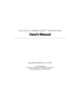
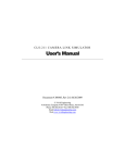
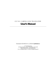
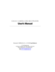
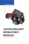
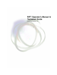
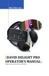
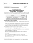
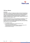
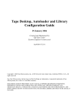
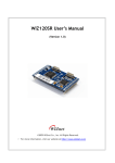
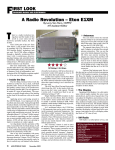
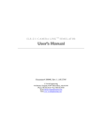
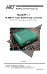
C LT- 3 5 3 R & C LT- 3 5 3 L C A M E R A L I N K T R A N S L ATO R User’s Manual Document # 201201, Rev 0.1, 4/19/2013 preliminary Vivid Engineering 159 Memorial Drive, Suite F • Shrewsbury, MA 01545 Phone 508.842.0165 • Fax 508.842.8930 Table of Contents 1. Introduction 1 1.1. Overview 1 1.2. Features 3 1.3. Functional Description 4 1.3.1. Rear-Panel Mode Switch Settings 7 1.3.2. Frame Grabber Clock Phase 8 1.3.3. Frame Grabber Timing Signal Polarity 8 1.3.4. Camera Serial Port Access 9 1.4. Typical Application 10 1.5. Specifications 12 2. Interface 13 2.1. Front Panel Connections 13 2.1.1. Camera Connector Signals 14 2.1.2. Frame Grabber Connector Signals 14 2.1.3. Cable Shield Grounding 14 2.1.4. Recommended Cable Connectors 14 2.2. Rear Panel 42 3. Mechanical 44 3.1. Dimensions 44 3.2. External Power Supply 45 4. Revision History 46 1. Introduction 1.1. Overview The CLT-353R and CLT-353L Camera Link 1 Translators enable the use of Camera Link cameras with frame grabbers incorporating RS-422 and LVDS parallel digital interfaces. The “R” and “L” versions support RS-422 and LVDS frame grabbers, respectively. The CLT-353’s are extremely flexible and can translate a wide range of single-channel, dual-channel, and color “base” configuration Camera Link cameras to parallel digital format. The CLT-353R/L translators are housed in sturdy, compact aluminum enclosures. The Camera Link interface standard enables the interoperability of cameras and frame grabbers, regardless of vendor. The Automated Imaging Association (AIA) sponsors the Camera Link program including the oversight Camera Link Committee, the self-certification program, and the product registry. The Camera Link specification may be downloaded from the AIA website, found at www.machinevisiononline.org 1 1 Vivid Engineering CAMERA Vivid Engineering CAMERA Camera Link Translator CLT-353R RS-422 FRAME GRABBER Camera Link Translator LVDS FRAME GRABBER 2 CLT-353L 1.2. Features • Enable use of Camera Link cameras with RS-422 and LVDS frame grabbers • Interfaces to a wide range of single-channel, dual-channel, and color Camera Link cameras. • “R” version supports RS-422 frame grabbers • “L” version supports LVDS frame grabbers • 85 MHz max pixel clock rate for “L” version • 32 MHz max pixel clock rate for “R” version • Camera serial communication via frame grabber interface or via rear-panel RS232 port • Selectable frame grabber timing signal polarity and clock phase • Minimal data pass-through latency • Isolated DC power input • Multi-nation power supply included, locking-plug power supply optional • Sturdy, compact aluminum enclosure w/ mounting flange • 3-year warrantee 3 1.3. Functional Description The CLT-353R/L Camera Link Translators enable the use of Camera Link cameras with frame grabbers incorporating parallel RS-422 and LVDS digital interfaces. Block diagrams of the CLT-353L and CLT-353R are provided in Figures 1-1 and 1-2, respectively. The CLT-353R is intended for use with RS-422 frame grabbers, and the CLT-353L for use with LVDS (EIA-644) frame grabbers. The CLT-353R/L camera interface incorporates the connector, signals, pinout, and chipset in compliance with the Camera Link specification. The CLT-353R/L incorporates the “base” configuration signal set, consisting of video data, camera control, and serial communications. The CLT353R/L supports single-channel (monochrome) cameras with 8/10/12/14/16-bit pixels, dual-channel 8/10/12-bit cameras, and 8-bit color cameras. The frame grabber interface outputs video data in parallel digital format using RS-422 or LVDS, depending on CLT-353 version. The interface incorporates a 68-pin SCSI-style connector. The latency (i.e. delay) of the video, control, and communication signals passing through the CLT-353R/L is minimal. This is an important criteria in time-critical applications. See Table 1.1 for CLT-353R/L latency specifications. Frame grabber clock and timing signal characteristics are selected using the rear-panel mode switch described in the next section The switch also selects which serial port is used to communicate with the camera; the serial port from the frame grabber, or a standard RS232 serial port accessed via the rear-panel DB-9 connector. Switch settings are defined in the following sections. The CLT-353R/L receives two LVDS camera control signals from the frame grabber and retransmits them as CC1 and CC2 to the Camera Link camera. These signals are often used to externally synchronize the camera (i.e. EXSYNC). The CLT-353L & CLT-353R camera interface incorporates LVDS devices for the serial communication signals (per Camera Link). The frame grabber interface serial signals are implemented using LVDS or RS-422 devices, depending on CLT-353 version. The CLT-353 is powered by an external wall plug-in power supply. A multi-nation power supply is standard. Optionally, the CLT-353R/L is available with a locking-plug power supply. The locking plug reduces the risk of accidental disconnection from the rear-panel power jack. The CLT-353R/L is also available without power supply. The CLT-353R/L DC power input is electrically isolated from the internal circuitry. This feature ensures compatibility with user power systems. 4 Mode Select Switch Pixel Data Channel Link Receiver Frame Valid, Line Valid, Data Valid Polarity Select Serial Comm Link Video Data Phase Shifter Clock Camera Control RS-422 RS-422 LVDS Receivers Receivers Xmtrs LVDS Transmitter LVDS Receiver Camera Control LVDS Rcvr LVDS Xmtr LVDS Xmtr LVDS Rcvr Serial Comm Link CLT-353L Camera Link Translator Figure 1-1: CLT-353L Block Diagram 5 Serial Port To PC RS-232 Port RS-232 To LVDS Frame Grabber To Camera Link Camera Video Data Pixel Alignment Mode Select Switch Pixel Data Channel Link Receiver Frame Valid, Line Valid, Data Valid Polarity Select Serial Comm Link Video Data Phase Shifter Clock Camera Control RS-422 RS-422 RS-422 Receivers Receivers Xmtrs LVDS Transmitter RS-422 Receiver LVDS Rcvr RS-422 Xmtr LVDS Xmtr RS-422 Rcvr CLT-353R Camera Link Translator Figure 1-2: CLT-353R Block Diagram 6 Serial Comm Link Serial Port To PC RS-232 Port RS-232 Camera Control To RS-422 Frame Grabber To Camera Link Camera Video Data Pixel Alignment 1.3.1. Rear-Panel Mode Switch Settings The CLT-353R/L incorporates a rear-panel mode select switch. The switch allows the user to specify timing signal polarities, clock characteristics, and serial port selection. The mode switch has eight positions. Two positions are reserved for future use. The functional assignments are defined in Figure 1-3 1 2 3 4 5 6 7 8 Reserved 0 1 Serial Select - frame grabber - RS-232 port 0 1 Data Valid Polarity - active-high (most common) - active-low 0 1 Frame Valid Polarity - active-high (most common) - active-low 0 1 Line Valid Polarity - active-high (most common) - active-low 00 01 10 11 Clock Phase Shifter - 0o (most common) - 90o - 180o - 270o 0 = "down" switch position 1 = "up" switch position Figure 1-3: Rear-Panel Mode Switch Definition 7 1.3.2. Frame Grabber Clock Phase The CLT-353R/L incorporates a phase shifter to optimize the clock /data timing relationship for the frame grabber. Positions 1&2 on the external mode select switch are used to select pixel clock phase shift. In most cases, the 0 degree phase shift setting is used which centers the rising edge of the pixel clock within the valid pixel/timing data interval. Alternatively, clock phase shifts of 90, 180, and 270 degrees are supported. The pixel clock phase shifter characteristics are illustrated in Figure 1-4. Pixel Data & Timing Signals Valid Pixel & Timing Data Pixel Clock w/ 0o shift Pixel Clock w/ 90o shift Pixel Clock w/ 180o shift Pixel Clock w/ 270o shift Figure 1-4: Pixel Clock Phase Options 1.3.3. Frame Grabber Timing Signal Polarity Frame grabber timing signal polarity characteristics are selected using the mode select switch. Position 3 is used to select the polarity of the line valid signal, position 4 is used to select the polarity of the frame valid signal, and position 5 is used to select the polarity of the data valid signal. In most cases, a “high” state on the line enable and frame enable signals is used to envelope valid lines and frames of video data, respectively. The settings enable the user to select either active-high or active-low polarities for each timing signal. The Camera Link interface includes a data valid signal to qualify the video signals coming from the camera. In most cases. This camera signal is held high as the video signals coming from the camera are always valid. In most cases the frame grabber can ignore the data valid signal. 8 1.3.4. Camera Serial Port Access The CLT-353R/L incorporates a provision that enables the user to communicate with the Camera Link camera via either the serial port that is part of the frame grabber interface, or via the rear-panel RS-232 port. The selection is made via switch position 6. The RS-232 serial port incorporates a standard 9-pin D-Sub (DB9) connector. A null modem cable is required for connecting the CLT-353R/L to a PC serial port, USB adapter, etc. 9 1.4. Typical Application A typical CLT-353R/L application is shown in Figure 1-5. The Camera Link camera is connected to the CLT-353L using a standard Camera Link cable. The CLT-353L is then connected to an LVDS frame grabber using a custom cable incorporating a 68-pin SCSIstyle connector at the CLT-353R/L end. Rear-panel modes switch settings are shown in Figure 1-6. The clock phase shifter is set for standard 00. The line valid, frame valid, and data valid polarities are set for the most common active-high polarities. Camera serial communication selection is via the frame grabber serial port. Therefore, no connection to the rear-panel RS-232 DB-9 connector is needed. CLT-353L Camera Link Translator Vivid Engineering Camera Link Translator CAMERA Camera Link Camera CLT-353L LVDS FRAME GRABBER Custom Cable (SCSI-Style) Standard Camera Link Cable LVDS Frame Grabber Figure 1-5: CLT-353R/L Typical Application 10 1 2 3 4 5 6 7 8 Reserved 0 Serial Select - frame grabber 0 Data Valid Polarity - active-high 0 Frame Valid Polarity - active-high 0 Line Valid Polarity - active-high 00 Clock Phase Shifter - 0o 0 = "down" switch position 1 = "up" switch position Figure 1-6: Example Mode Settings 11 1.5. Specifications Table 1-1: CLT-353R/L Specifications Feature Specification Camera Interface Camera Link “base” configuration. Camera Connector 26-pin MDR type Frame Grabber Interface Parallel differential data format - “R” version = RS-422 - “L” version = LVDS (EIA-644) Frame Grabber Connector 68-pin HD type (SCSI-3) Frequency Range 20 - 85 MHz (“L” version) 20 - 32 MHz (“R” version) Mode Selection Rear-panel 8-position DIP switch Serial Port Standard RS-232 w/ 9-pin male D-Sub connector (DB9) Latency Video path: 3 camera pixel clock cycles Control signals: 20 ns max Power Supply Universal wall style w/ outlet plug set Power Plug 2.1 x 5.5 mm, center-positive. Locking style optional Power Requirements 4.5 – 9.0 VDC, internally isolated - “R” version = TBD mA at 5 VDC (typical) - “L” version = 340 mA at 5 VDC (typical) Cabinet Dimensions 5.28” (L) x 1.18” (H) x 7.12” (D) Weight TBD oz Operating Temperature Range 0 to 50° C Storage Temperature Range -25 to 75° C Relative Humidity 0 to 90%, non-condensing 12 2. Interface 2.1. Front Panel Connections A CLT-353R/L Camera Link Translator front panel is shown in Figure 2-1 (CLT-353R shown). The front panel contains two video connectors; one for connecting to the camera and one for connecting to the frame grabber. The camera connector is a 26-pin MDR type (MDR-26). The frame grabber connector is a 68-pin HD68 SCSI-3 type (TE Connectivity p/n 5787170-7) with 2-56 jackscrew sockets (TE Connectivity p/n 749087-2). Figure 2-2 identifies the pin positions. . Vivid Engineering Camera Link Translator CLT-353R RS-422 FRAME GRABBER CAMERA Figure 2-1: CLT-353R/L Front Panel pin 34 pin 1 pin 68 pin 35 Figure 2-2: HD68 Connector Pin Positions 13 2.1.1. Camera Connector Signals The MDR-26 video connector signal assignments comply with the Camera Link “base” configuration. The connector signal assignments correspond to the frame grabber interface defined in the Camera Link Specification. This provides compatibility with standard Camera Link cables. 2.1.2. Frame Grabber Connector Signals Tables 2-1 through 2-5 identify the 68-pin frame grabber connector signal assignments for single-channel pixel data modes (1x8, 1x10, 1x12, 1x14, and 1x16). Tables 2-6 through 2-8 identify the signal assignment for dual-channel modes (2x8, 2x10, 2x12), and Table 2-9 identifies the signal assignment for color mode (3x8). The appropriate table must be used when making a camera cable for use with the CLT-353R/L. 2.1.3. Cable Shield Grounding Camera and frame grabber cable “outer” shields are connected to the CLT-353R/L aluminum case. Case and endplate contacting surfaces are unpainted, providing a Faraday cage to shield internal circuitry. The case is isolated from the CLT-353R/L circuitry and the Camera Link cable “inner” shield. 2.1.4. Recommended Cable Connectors The following is a list of recommended CLT-353R/L mating connectors (plugs) and housings (backshells) for use in cables that connect the CLT-353R/L to the frame grabber: Plug, TE Connectivity p/n 1-5750913-7 Plug, TE Connectivity p/n 5750913-7 Plug, TE Connectivity p/n 5749111-6 Plug, TE Connectivity p/n 5749621-7 Backshell, TE Connectivity p/n 5786152-3 Backshell, TE Connectivity p/n 5750752-1 Backshell, TE Connectivity p/n 5750752-3 Other suitable connector manufacturers include NorComp, Acon, and Harting. 14 Table 2-1: Frame Grabber Connector, 8-bit Single-Channel Mode Camera Interface Signal Name Camera Interface Connector Pin Signal Direction A0 + 1 CLT-353 → FG A0 - 35 CLT-353 → FG A1 + 2 CLT-353 → FG A1 - 36 CLT-353 → FG A2 + 3 CLT-353 → FG A2 - 37 CLT-353 → FG A3 + 4 CLT-353 → FG A3 - 38 CLT-353 → FG A4 + 5 CLT-353 → FG A4 - 39 CLT-353 → FG A5 + 6 CLT-353 → FG A5 - 40 CLT-353 → FG A6 + 7 CLT-353 → FG A6 - 41 CLT-353 → FG 1 8 CLT-353 → FG A7 - 1 42 CLT-353 → FG Unused Output 9 CLT-353 → FG Unused Output 43 CLT-353 → FG Unused Output 10 CLT-353 → FG Unused Output 44 CLT-353 → FG Unused Output 11 CLT-353 → FG Unused Output 45 CLT-353 → FG Unused Output 12 CLT-353 → FG Unused Output 46 CLT-353 → FG Unused Output 13 CLT-353 → FG Unused Output 47 CLT-353 → FG Unused Output 14 CLT-353 → FG Unused Output 48 CLT-353 → FG Unused Output 15 CLT-353 → FG Unused Output 49 CLT-353 → FG A7 + 15 Notes Unused Output 16 CLT-353 → FG Unused Output 50 CLT-353 → FG Unused Output 17 CLT-353 → FG Unused Output 51 CLT-353 → FG Unused Output 18 CLT-353 → FG Unused Output 52 CLT-353 → FG Unused Output 19 CLT-353 → FG Unused Output 53 CLT-353 → FG Unused Output 20 CLT-353 → FG Unused Output 54 CLT-353 → FG Unused Output 21 CLT-353 → FG Unused Output 55 CLT-353 → FG Unused Output 22 CLT-353 → FG Unused Output 56 CLT-353 → FG Unused Output 23 CLT-353 → FG Unused Output 57 CLT-353 → FG Unused Output 24 CLT-353 → FG Unused Output 58 CLT-353 → FG Mode Control 1 + 25 FG → CLT-353 CC1 from FG Mode Control 1 - 59 FG → CLT-353 ” Mode Control 2 + 26 FG → CLT-353 CC2 from FG Mode Control 2 - 60 FG → CLT-353 ” Serial Control In + 27 FG → CLT-353 serial comm, FG to cam Serial Control In - 61 FG → CLT-353 “ Serial Control Out + 28 CLT-353 → FG serial comm, cam to FG Serial Control Out - 62 CLT-353 → FG “ reserved 29 reserved 63 Frame Enable + 30 CLT-353 → FG “frame valid” Frame Enable - 64 CLT-353 → FG “ Line Enable + 31 CLT-353 → FG “line valid” Line Enable - 65 CLT-353 → FG “ Data Valid + 32 CLT-353 → FG “data valid” Data Valid - 66 CLT-353 → FG “ Pixel Strobe + 33 CLT-353 → FG “pixel clock” Pixel Strobe - 67 CLT-353 → FG “ 16 Ground 34 N/A tied to digital ground Ground 68 N/A tied to digital ground 1 Pixel “A” MSB “FG” = Frame Grabber “cam” = Camera 17 Table 2-2: Frame Grabber Connector, 10-bit Single-Channel Mode Camera Interface Signal Name Camera Interface Connector Pin Signal Direction A0 + 1 CLT-353 → FG A0 - 35 CLT-353 → FG A1 + 2 CLT-353 → FG A1 - 36 CLT-353 → FG A2 + 3 CLT-353 → FG A2 - 37 CLT-353 → FG A3 + 4 CLT-353 → FG A3 - 38 CLT-353 → FG A4 + 5 CLT-353 → FG A4 - 39 CLT-353 → FG A5 + 6 CLT-353 → FG A5 - 40 CLT-353 → FG A6 + 7 CLT-353 → FG A6 - 41 CLT-353 → FG A7 + 8 CLT-353 → FG A7 - 42 CLT-353 → FG A8 + 9 CLT-353 → FG A8 - 43 CLT-353 → FG 1 10 CLT-353 → FG A9 - 1 44 CLT-353 → FG Unused Output 11 CLT-353 → FG Unused Output 45 CLT-353 → FG Unused Output 12 CLT-353 → FG Unused Output 46 CLT-353 → FG Unused Output 13 CLT-353 → FG Unused Output 47 CLT-353 → FG Unused Output 14 CLT-353 → FG Unused Output 48 CLT-353 → FG Unused Output 15 CLT-353 → FG Unused Output 49 CLT-353 → FG A9 + 18 Notes Unused Output 16 CLT-353 → FG Unused Output 50 CLT-353 → FG Unused Output 17 CLT-353 → FG Unused Output 51 CLT-353 → FG Unused Output 18 CLT-353 → FG Unused Output 52 CLT-353 → FG Unused Output 19 CLT-353 → FG Unused Output 53 CLT-353 → FG Unused Output 20 CLT-353 → FG Unused Output 54 CLT-353 → FG Unused Output 21 CLT-353 → FG Unused Output 55 CLT-353 → FG Unused Output 22 CLT-353 → FG Unused Output 56 CLT-353 → FG Unused Output 23 CLT-353 → FG Unused Output 57 CLT-353 → FG Unused Output 24 CLT-353 → FG Unused Output 58 CLT-353 → FG Mode Control 1 + 25 FG → CLT-353 CC1 from FG Mode Control 1 - 59 FG → CLT-353 ” Mode Control 2 + 26 FG → CLT-353 CC2 from FG Mode Control 2 - 60 FG → CLT-353 ” Serial Control In + 27 FG → CLT-353 serial comm, FG to cam Serial Control In - 61 FG → CLT-353 “ Serial Control Out + 28 CLT-353 → FG serial comm, cam to FG Serial Control Out - 62 CLT-353 → FG “ reserved 29 reserved 63 Frame Enable + 30 CLT-353 → FG “frame valid” Frame Enable - 64 CLT-353 → FG “ Line Enable + 31 CLT-353 → FG “line valid” Line Enable - 65 CLT-353 → FG “ Data Valid + 32 CLT-353 → FG “data valid” Data Valid - 66 CLT-353 → FG “ Pixel Strobe + 33 CLT-353 → FG “pixel clock” Pixel Strobe - 67 CLT-353 → FG “ 19 Ground 34 N/A tied to digital ground Ground 68 N/A tied to digital ground 1 Pixel “A” MSB “FG” = Frame Grabber “cam” = Camera 20 Table 2-3: Frame Grabber Connector, 12-bit Single-Channel Mode Camera Interface Signal Name Camera Interface Connector Pin Signal Direction A0 + 1 CLT-353 → FG A0 - 35 CLT-353 → FG A1 + 2 CLT-353 → FG A1 - 36 CLT-353 → FG A2 + 3 CLT-353 → FG A2 - 37 CLT-353 → FG A3 + 4 CLT-353 → FG A3 - 38 CLT-353 → FG A4 + 5 CLT-353 → FG A4 - 39 CLT-353 → FG A5 + 6 CLT-353 → FG A5 - 40 CLT-353 → FG A6 + 7 CLT-353 → FG A6 - 41 CLT-353 → FG A7 + 8 CLT-353 → FG A7 - 42 CLT-353 → FG A8 + 9 CLT-353 → FG A8 - 43 CLT-353 → FG A9 + 10 CLT-353 → FG A9 - 44 CLT-353 → FG A10 + 11 CLT-353 → FG A10 - 45 CLT-353 → FG 1 12 CLT-353 → FG 1 A11 - 46 CLT-353 → FG Unused Output 13 CLT-353 → FG Unused Output 47 CLT-353 → FG Unused Output 14 CLT-353 → FG Unused Output 48 CLT-353 → FG Unused Output 15 CLT-353 → FG Unused Output 49 CLT-353 → FG A11 + 21 Notes Unused Output 16 CLT-353 → FG Unused Output 50 CLT-353 → FG Unused Output 17 CLT-353 → FG Unused Output 51 CLT-353 → FG Unused Output 18 CLT-353 → FG Unused Output 52 CLT-353 → FG Unused Output 19 CLT-353 → FG Unused Output 53 CLT-353 → FG Unused Output 20 CLT-353 → FG Unused Output 54 CLT-353 → FG Unused Output 21 CLT-353 → FG Unused Output 55 CLT-353 → FG Unused Output 22 CLT-353 → FG Unused Output 56 CLT-353 → FG Unused Output 23 CLT-353 → FG Unused Output 57 CLT-353 → FG Unused Output 24 CLT-353 → FG Unused Output 58 CLT-353 → FG Mode Control 1 + 25 FG → CLT-353 CC1 from FG Mode Control 1 - 59 FG → CLT-353 ” Mode Control 2 + 26 FG → CLT-353 CC2 from FG Mode Control 2 - 60 FG → CLT-353 ” Serial Control In + 27 FG → CLT-353 serial comm, FG to cam Serial Control In - 61 FG → CLT-353 “ Serial Control Out + 28 CLT-353 → FG serial comm, cam to FG Serial Control Out - 62 CLT-353 → FG “ reserved 29 reserved 63 Frame Enable + 30 CLT-353 → FG “frame valid” Frame Enable - 64 CLT-353 → FG “ Line Enable + 31 CLT-353 → FG “line valid” Line Enable - 65 CLT-353 → FG “ Data Valid + 32 CLT-353 → FG “data valid” Data Valid - 66 CLT-353 → FG “ Pixel Strobe + 33 CLT-353 → FG “pixel clock” Pixel Strobe - 67 CLT-353 → FG “ 22 Ground 34 N/A tied to digital ground Ground 68 N/A tied to digital ground 1 Pixel “A” MSB “FG” = Frame Grabber “cam” = Camera 23 Table 2-4: Frame Grabber Connector, 14-bit Single-Channel Mode Camera Interface Signal Name Camera Interface Connector Pin Signal Direction A0 + 1 CLT-353 → FG A0 - 35 CLT-353 → FG A1 + 2 CLT-353 → FG A1 - 36 CLT-353 → FG A2 + 3 CLT-353 → FG A2 - 37 CLT-353 → FG A3 + 4 CLT-353 → FG A3 - 38 CLT-353 → FG A4 + 5 CLT-353 → FG A4 - 39 CLT-353 → FG A5 + 6 CLT-353 → FG A5 - 40 CLT-353 → FG A6 + 7 CLT-353 → FG A6 - 41 CLT-353 → FG A7 + 8 CLT-353 → FG A7 - 42 CLT-353 → FG A8 + 9 CLT-353 → FG A8 - 43 CLT-353 → FG A9 + 10 CLT-353 → FG A9 - 44 CLT-353 → FG A10 + 11 CLT-353 → FG A10 - 45 CLT-353 → FG A11 + 12 CLT-353 → FG A11 - 46 CLT-353 → FG A12 + 13 CLT-353 → FG A12 - 47 CLT-353 → FG 1 14 CLT-353 → FG 1 A13 - 48 CLT-353 → FG Unused Output 15 CLT-353 → FG Unused Output 49 CLT-353 → FG A13 + 24 Notes Unused Output 16 CLT-353 → FG Unused Output 50 CLT-353 → FG Unused Output 17 CLT-353 → FG Unused Output 51 CLT-353 → FG Unused Output 18 CLT-353 → FG Unused Output 52 CLT-353 → FG Unused Output 19 CLT-353 → FG Unused Output 53 CLT-353 → FG Unused Output 20 CLT-353 → FG Unused Output 54 CLT-353 → FG Unused Output 21 CLT-353 → FG Unused Output 55 CLT-353 → FG Unused Output 22 CLT-353 → FG Unused Output 56 CLT-353 → FG Unused Output 23 CLT-353 → FG Unused Output 57 CLT-353 → FG Unused Output 24 CLT-353 → FG Unused Output 58 CLT-353 → FG Mode Control 1 + 25 FG → CLT-353 CC1 from FG Mode Control 1 - 59 FG → CLT-353 ” Mode Control 2 + 26 FG → CLT-353 CC2 from FG Mode Control 2 - 60 FG → CLT-353 ” Serial Control In + 27 FG → CLT-353 serial comm, FG to cam Serial Control In - 61 FG → CLT-353 “ Serial Control Out + 28 CLT-353 → FG serial comm, cam to FG Serial Control Out - 62 CLT-353 → FG “ reserved 29 reserved 63 Frame Enable + 30 CLT-353 → FG “frame valid” Frame Enable - 64 CLT-353 → FG “ Line Enable + 31 CLT-353 → FG “line valid” Line Enable - 65 CLT-353 → FG “ Data Valid + 32 CLT-353 → FG “data valid” Data Valid - 66 CLT-353 → FG “ Pixel Strobe + 33 CLT-353 → FG “pixel clock” Pixel Strobe - 67 CLT-353 → FG “ 25 Ground 34 N/A tied to digital ground Ground 68 N/A tied to digital ground 1 Pixel “A” MSB “FG” = Frame Grabber “cam” = Camera 26 Table 2-5: Frame Grabber Connector, 16-bit Single-Channel Mode Camera Interface Signal Name Camera Interface Connector Pin Signal Direction A0 + 1 CLT-353 → FG A0 - 35 CLT-353 → FG A1 + 2 CLT-353 → FG A1 - 36 CLT-353 → FG A2 + 3 CLT-353 → FG A2 - 37 CLT-353 → FG A3 + 4 CLT-353 → FG A3 - 38 CLT-353 → FG A4 + 5 CLT-353 → FG A4 - 39 CLT-353 → FG A5 + 6 CLT-353 → FG A5 - 40 CLT-353 → FG A6 + 7 CLT-353 → FG A6 - 41 CLT-353 → FG A7 + 8 CLT-353 → FG A7 - 42 CLT-353 → FG A8 + 9 CLT-353 → FG A8 - 43 CLT-353 → FG A9 + 10 CLT-353 → FG A9 - 44 CLT-353 → FG A10 + 11 CLT-353 → FG A10 - 45 CLT-353 → FG A11 + 12 CLT-353 → FG A11 - 46 CLT-353 → FG A12 + 13 CLT-353 → FG A12 - 47 CLT-353 → FG A13 + 14 CLT-353 → FG A13 - 48 CLT-353 → FG A14 + 15 CLT-353 → FG A14 - 49 CLT-353 → FG 27 Notes 1 16 CLT-353 → FG 1 A15 - 50 CLT-353 → FG Unused Output 17 CLT-353 → FG Unused Output 51 CLT-353 → FG Unused Output 18 CLT-353 → FG Unused Output 52 CLT-353 → FG Unused Output 19 CLT-353 → FG Unused Output 53 CLT-353 → FG Unused Output 20 CLT-353 → FG Unused Output 54 CLT-353 → FG Unused Output 21 CLT-353 → FG Unused Output 55 CLT-353 → FG Unused Output 22 CLT-353 → FG Unused Output 56 CLT-353 → FG Unused Output 23 CLT-353 → FG Unused Output 57 CLT-353 → FG Unused Output 24 CLT-353 → FG Unused Output 58 CLT-353 → FG A15 + Mode Control 1 + 25 FG → CLT-353 CC1 from FG Mode Control 1 - 59 FG → CLT-353 ” Mode Control 2 + 26 FG → CLT-353 CC2 from FG Mode Control 2 - 60 FG → CLT-353 ” Serial Control In + 27 FG → CLT-353 serial comm, FG to cam Serial Control In - 61 FG → CLT-353 “ Serial Control Out + 28 CLT-353 → FG serial comm, cam to FG Serial Control Out - 62 CLT-353 → FG “ reserved 29 reserved 63 Frame Enable + 30 CLT-353 → FG “frame valid” Frame Enable - 64 CLT-353 → FG “ Line Enable + 31 CLT-353 → FG “line valid” Line Enable - 65 CLT-353 → FG “ Data Valid + 32 CLT-353 → FG “data valid” Data Valid - 66 CLT-353 → FG “ Pixel Strobe + 33 CLT-353 → FG “pixel clock” Pixel Strobe - 67 CLT-353 → FG “ 28 Ground 34 N/A tied to digital ground Ground 68 N/A tied to digital ground 1 Pixel “A” MSB “FG” = Frame Grabber “cam” = Camera 29 Table 2-6: Frame Grabber Connector, 8-bit Dual-Channel Mode Camera Interface Signal Name Camera Interface Connector Pin Signal Direction A0 + 1 CLT-353 → FG A0 - 35 CLT-353 → FG A1 + 2 CLT-353 → FG A1 - 36 CLT-353 → FG A2 + 3 CLT-353 → FG A2 - 37 CLT-353 → FG A3 + 4 CLT-353 → FG A3 - 38 CLT-353 → FG A4 + 5 CLT-353 → FG A4 - 39 CLT-353 → FG A5 + 6 CLT-353 → FG A5 - 40 CLT-353 → FG A6 + 7 CLT-353 → FG A6 - 41 CLT-353 → FG 1 8 CLT-353 → FG A7 - 1 42 CLT-353 → FG B0 + 9 CLT-353 → FG B0 - 43 CLT-353 → FG B1 + 10 CLT-353 → FG B1 - 44 CLT-353 → FG B2 + 11 CLT-353 → FG A7 + B2 - 45 CLT-353 → FG B3 + 12 CLT-353 → FG B3 - 46 CLT-353 → FG B4 + 13 CLT-353 → FG B4 - 47 CLT-353 → FG B5 + 14 CLT-353 → FG B5 - 48 CLT-353 → FG B6 + 15 CLT-353 → FG B6 - 49 CLT-353 → FG 30 Notes 2 16 CLT-353 → FG 2 B7 - 50 CLT-353 → FG Unused Output 17 CLT-353 → FG Unused Output 51 CLT-353 → FG Unused Output 18 CLT-353 → FG Unused Output 52 CLT-353 → FG Unused Output 19 CLT-353 → FG Unused Output 53 CLT-353 → FG Unused Output 20 CLT-353 → FG Unused Output 54 CLT-353 → FG Unused Output 21 CLT-353 → FG Unused Output 55 CLT-353 → FG Unused Output 22 CLT-353 → FG Unused Output 56 CLT-353 → FG Unused Output 23 CLT-353 → FG Unused Output 57 CLT-353 → FG Unused Output 24 CLT-353 → FG Unused Output 58 CLT-353 → FG B7 + Mode Control 1 + 25 FG → CLT-353 CC1 from FG Mode Control 1 - 59 FG → CLT-353 ” Mode Control 2 + 26 FG → CLT-353 CC2 from FG Mode Control 2 - 60 FG → CLT-353 ” Serial Control In + 27 FG → CLT-353 serial comm, FG to cam Serial Control In - 61 FG → CLT-353 “ Serial Control Out + 28 CLT-353 → FG serial comm, cam to FG Serial Control Out - 62 CLT-353 → FG “ reserved 29 reserved 63 Frame Enable + 30 CLT-353 → FG “frame valid” Frame Enable - 64 CLT-353 → FG “ Line Enable + 31 CLT-353 → FG “line valid” Line Enable - 65 CLT-353 → FG “ Data Valid + 32 CLT-353 → FG “data valid” Data Valid - 66 CLT-353 → FG “ Pixel Strobe + 33 CLT-353 → FG “pixel clock” Pixel Strobe - 67 CLT-353 → FG “ 31 Ground 34 N/A tied to digital ground Ground 68 N/A tied to digital ground 1 Pixel “A” MSB 2 Pixel “B” MSB “FG” = Frame Grabber “cam” = Camera 32 Table 2-7: Frame Grabber Connector, 10-bit Dual-Channel Mode Camera Interface Signal Name Camera Interface Connector Pin Signal Direction A0 + 1 CLT-353 → FG A0 - 35 CLT-353 → FG A1 + 2 CLT-353 → FG A1 - 36 CLT-353 → FG A2 + 3 CLT-353 → FG A2 - 37 CLT-353 → FG A3 + 4 CLT-353 → FG A3 - 38 CLT-353 → FG A4 + 5 CLT-353 → FG A4 - 39 CLT-353 → FG A5 + 6 CLT-353 → FG A5 - 40 CLT-353 → FG A6 + 7 CLT-353 → FG A6 - 41 CLT-353 → FG A7 + 8 CLT-353 → FG A7 - 42 CLT-353 → FG A8 + 9 CLT-353 → FG A8 - 43 CLT-353 → FG 1 10 CLT-353 → FG A9 - 1 44 CLT-353 → FG Unused Output 11 CLT-353 → FG Unused Output 45 CLT-353 → FG Unused Output 12 CLT-353 → FG Unused Output 46 CLT-353 → FG B8 + 13 CLT-353 → FG B8 - A9 + 47 CLT-353 → FG 2 14 CLT-353 → FG 2 B9 - 48 CLT-353 → FG Unused Output 15 CLT-353 → FG Unused Output 49 CLT-353 → FG B9 + 33 Notes Unused Output 16 CLT-353 → FG Unused Output 50 CLT-353 → FG B0 + 17 CLT-353 → FG B0 - 51 CLT-353 → FG B1 + 18 CLT-353 → FG B1 - 52 CLT-353 → FG B2 + 19 CLT-353 → FG B2 - 53 CLT-353 → FG B3 + 20 CLT-353 → FG B3 - 54 CLT-353 → FG B4 + 21 CLT-353 → FG B4 - 55 CLT-353 → FG B5 + 22 CLT-353 → FG B5 - 56 CLT-353 → FG B6 + 23 CLT-353 → FG B6 - 57 CLT-353 → FG B7 + 24 CLT-353 → FG B7 - 58 CLT-353 → FG Mode Control 1 + 25 FG → CLT-353 CC1 from FG Mode Control 1 - 59 FG → CLT-353 ” Mode Control 2 + 26 FG → CLT-353 CC2 from FG Mode Control 2 - 60 FG → CLT-353 ” Serial Control In + 27 FG → CLT-353 serial comm, FG to cam Serial Control In - 61 FG → CLT-353 “ Serial Control Out + 28 CLT-353 → FG serial comm, cam to FG Serial Control Out - 62 CLT-353 → FG “ reserved 29 reserved 63 Frame Enable + 30 CLT-353 → FG “frame valid” Frame Enable - 64 CLT-353 → FG “ Line Enable + 31 CLT-353 → FG “line valid” Line Enable - 65 CLT-353 → FG “ Data Valid + 32 CLT-353 → FG “data valid” Data Valid - 66 CLT-353 → FG “ Pixel Strobe + 33 CLT-353 → FG “pixel clock” Pixel Strobe - 67 CLT-353 → FG “ 34 Ground 34 N/A tied to digital ground Ground 68 N/A tied to digital ground 1 Pixel “A” MSB 2 Pixel “B” MSB “FG” = Frame Grabber “cam” = Camera 35 Table 2-8: Frame Grabber Connector, 12-bit Dual-Channel Mode Camera Interface Signal Name Camera Interface Connector Pin Signal Direction A0 + 1 CLT-353 → FG A0 - 35 CLT-353 → FG A1 + 2 CLT-353 → FG A1 - 36 CLT-353 → FG A2 + 3 CLT-353 → FG A2 - 37 CLT-353 → FG A3 + 4 CLT-353 → FG A3 - 38 CLT-353 → FG A4 + 5 CLT-353 → FG A4 - 39 CLT-353 → FG A5 + 6 CLT-353 → FG A5 - 40 CLT-353 → FG A6 + 7 CLT-353 → FG A6 - 41 CLT-353 → FG A7 + 8 CLT-353 → FG A7 - 42 CLT-353 → FG A8 + 9 CLT-353 → FG A8 - 43 CLT-353 → FG A9 + 10 CLT-353 → FG A9 - 44 CLT-353 → FG A10 + 11 CLT-353 → FG A10 - 45 CLT-353 → FG 1 12 CLT-353 → FG 1 A11 - 46 CLT-353 → FG B8 + 13 CLT-353 → FG A11 + B8 - 47 CLT-353 → FG B9 + 14 CLT-353 → FG B9 - 48 CLT-353 → FG B10 + 15 CLT-353 → FG B10 - 49 CLT-353 → FG 36 Notes 2 16 CLT-353 → FG 2 B11 - 50 CLT-353 → FG B0 + 17 CLT-353 → FG B0 - 51 CLT-353 → FG B1 + 18 CLT-353 → FG B1 - 52 CLT-353 → FG B2 + 19 CLT-353 → FG B11 + B2 - 53 CLT-353 → FG B3 + 20 CLT-353 → FG B3 - 54 CLT-353 → FG B4 + 21 CLT-353 → FG B4 - 55 CLT-353 → FG B5 + 22 CLT-353 → FG B5 - 56 CLT-353 → FG B6 + 23 CLT-353 → FG B6 - 57 CLT-353 → FG B7 + 24 CLT-353 → FG B7 - 58 CLT-353 → FG Mode Control 1 + 25 FG → CLT-353 CC1 from FG Mode Control 1 - 59 FG → CLT-353 ” Mode Control 2 + 26 FG → CLT-353 CC2 from FG Mode Control 2 - 60 FG → CLT-353 ” Serial Control In + 27 FG → CLT-353 serial comm, FG to cam Serial Control In - 61 FG → CLT-353 “ Serial Control Out + 28 CLT-353 → FG serial comm, cam to FG Serial Control Out - 62 CLT-353 → FG “ reserved 29 reserved 63 Frame Enable + 30 CLT-353 → FG “frame valid” Frame Enable - 64 CLT-353 → FG “ Line Enable + 31 CLT-353 → FG “line valid” Line Enable - 65 CLT-353 → FG “ Data Valid + 32 CLT-353 → FG “data valid” Data Valid - 66 CLT-353 → FG “ Pixel Strobe + 33 CLT-353 → FG “pixel clock” Pixel Strobe - 67 CLT-353 → FG “ 37 Ground 34 N/A tied to digital ground Ground 68 N/A tied to digital ground 1 Pixel “A” MSB 2 Pixel “B” MSB “FG” = Frame Grabber “cam” = Camera 38 Table 2-9: Frame Grabber Connector, Color Mode Camera Interface Signal Name Camera Interface Connector Pin Signal Direction R0 + 1 CLT-353 → FG R0 - 35 CLT-353 → FG R1 + 2 CLT-353 → FG R1 - 36 CLT-353 → FG R2 + 3 CLT-353 → FG R2 - 37 CLT-353 → FG R3 + 4 CLT-353 → FG R3 - 38 CLT-353 → FG R4 + 5 CLT-353 → FG R4 - 39 CLT-353 → FG R5 + 6 CLT-353 → FG R5 - 40 CLT-353 → FG R6 + 7 CLT-353 → FG R6 - 41 CLT-353 → FG 1 8 CLT-353 → FG R7 - 1 42 CLT-353 → FG G0 + 9 CLT-353 → FG G0 - 43 CLT-353 → FG G1 + 10 CLT-353 → FG G1 - 44 CLT-353 → FG G2 + 11 CLT-353 → FG R7 + G2 - 45 CLT-353 → FG G3 + 12 CLT-353 → FG G3 - 46 CLT-353 → FG G4 + 13 CLT-353 → FG G4 - 47 CLT-353 → FG G5 + 14 CLT-353 → FG G5 - 48 CLT-353 → FG G6 + 15 CLT-353 → FG G6 - 49 CLT-353 → FG 39 Notes 2 16 CLT-353 → FG 2 G7 - 50 CLT-353 → FG B0 + 17 CLT-353 → FG B0 - 51 CLT-353 → FG B1 + 18 CLT-353 → FG B1 - 52 CLT-353 → FG B2 + 19 CLT-353 → FG G7 + B2 - 53 CLT-353 → FG B3 + 20 CLT-353 → FG B3 - 54 CLT-353 → FG B4 + 21 CLT-353 → FG B4 - 55 CLT-353 → FG B5 + 22 CLT-353 → FG B5 - 56 CLT-353 → FG B6 + 23 CLT-353 → FG B6 - 57 CLT-353 → FG 3 24 CLT-353 → FG 3 58 CLT-353 → FG B7 + B7 - Mode Control 1 + 25 FG → CLT-353 CC1 from FG Mode Control 1 - 59 FG → CLT-353 ” Mode Control 2 + 26 FG → CLT-353 CC2 from FG Mode Control 2 - 60 FG → CLT-353 ” Serial Control In + 27 FG → CLT-353 serial comm, FG to cam Serial Control In - 61 FG → CLT-353 “ Serial Control Out + 28 CLT-353 → FG serial comm, cam to FG Serial Control Out - 62 CLT-353 → FG “ reserved 29 reserved 63 Frame Enable + 30 CLT-353 → FG “frame valid” Frame Enable - 64 CLT-353 → FG “ Line Enable + 31 CLT-353 → FG “line valid” Line Enable - 65 CLT-353 → FG “ Data Valid + 32 CLT-353 → FG “data valid” Data Valid - 66 CLT-353 → FG “ Pixel Strobe + 33 CLT-353 → FG “pixel clock” Pixel Strobe - 67 CLT-353 → FG “ 40 Ground 34 N/A tied to digital ground Ground 68 N/A tied to digital ground 1 Pixel “R” MSB (red) 2 Pixel “G” MSB (green) 3 Pixel “B” MSB (blue) “FG” = Frame Grabber “cam” = Camera 41 2.2. Rear Panel The CLT-353R/L Camera Link Translator rear panel is shown in Figure 2-3. The rear panel contains an 8-position mode select DIP switch, power on indicator, DC power jack, and RS-232 port connector. The DC power jack accepts either a standard 2.1 x 5.5 mm barrel-style power plug, or a special locking version plug. The locking plug has bayonet-style “ears” on the barrel. Once inserted, the barrel may be turned ¼ turn clockwise. This locks the connector in place and provides retention. The locking plug is removed by first turning the barrel ¼ turn counterclockwise, and then pulling out the plug from the unit. Plug polarity is centerpositive. The recommended locking power plug for use with the CLT-353R/L is Philmore p/n 2150. The RS-232 serial port connector is a standard 9-pin male D-Sub type (DB9). Figure 2-4 identifies the DB9 pin positions. The DB9 connector signal assignments are compliant with the RS-232 serial interface standard. Table 2-3 identifies the DB9 signal assignments. MODE RS-232 PWR Figure 2-3: CLT-353R/L Rear Panel 42 5 VDC pin 1 pin 5 pin 6 pin 9 Figure 2-4: DB9 Connector Pin Positions Table 2-3: DB9 Connector RS-232 Signal Name Received Line Signal Detect DB9 Pin# Signal Direction Notes 1 N/A tied to pins 4 & 6 Received Data 2 PC → CLT-353 Transmitted Data 3 CLT-353 → PC Data Terminal Ready 4 N/A tied to pins 1 & 6 Signal Ground (common) 5 N/A tied to digital ground DCE Ready 6 N/A tied to pins 1 & 4 Request To Send 7 N/A tied to pin 8 Clear To Send 8 N/A tied to pin 7 Ring Indicator 9 N/A no connection “PC” = Control PC 43 3. Mechanical 3.1. Dimensions The CLT-353R/L Camera Link Translator cabinet dimensions are shown in Figure 3-1 (CLT-353R shown). ou nt in g fla CLT-353R m Camera Link Translator RS-422 FRAME GRABBER CAMERA 7. 12 "( in cl ud in g 1.18" Vivid Engineering ng e) The CLT-353R/L is housed in a sturdy aluminum enclosure. The body is extruded aluminum, with detachable front and rear endplates. The enclosure incorporates a mounting flange. The flange contains four predrilled holes (0.15” diameter) for convenient equipment mounting. A mounting footprint drawing is provided in Figure 3-2. 5.28" Figure 3-1: CLT-353R/L Cabinet Dimensions 44 Mounting Holes (4): 0.15" dia 6.62" 7.12" (Rear) (Front ) 5.00" 5.28" Figure 3-2: Mounting Footprint Drawing 3.2. External Power Supply The CLT-353R/L is powered by 4.5 – 9.0 VDC and incorporates a 2.1 x 5.5 mm DC power jack that accepts either a standard barrel-style power plug, or a special locking version (see Section 2.2). Power plug polarity is center-positive. The CLT-353R/L includes a multi-nation wall-mount power supply that handles a wide power range (90-264 VAC, 47-63 Hz) and comes with a set of outlet plugs suitable for most countries (US, Europe, UK, etc). The CLT-353R/L may also be purchased with a locking-plug power supply, or without power supply. 45 4. Revision History Table 4-1: CLT-353R & CLT-353L User’s Manual Revision History Document ID # Date 201201-0.1 4/19/2013 Changes Preliminary release of manual 46