1
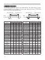
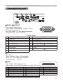
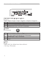
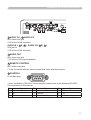
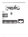
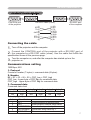
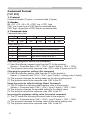
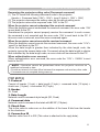
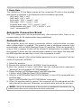
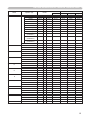
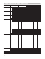
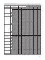
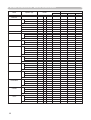
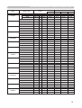
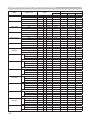
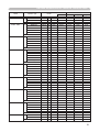
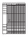
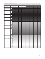
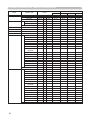
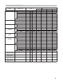
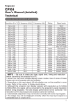
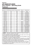
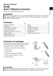
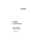
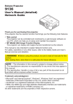
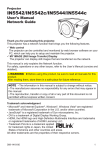
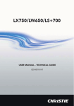
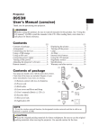
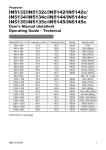
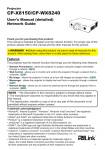
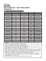
Projector
8949H
User's Manual – Operating Guide
Technical
Example of computer signal
Resolution (H x V) H. frequency (kHz) V. frequency (Hz)
720 x 400
640 x 480
640 x 480
640 x 480
640 x 480
800 x 600
800 x 600
800 x 600
800 x 600
800 x 600
832 x 624
1024 x 768
1024 x 768
1024 x 768
1024 x 768
1152 x 864
1280 x 960
1280 x 1024
1280 x 1024
*1280 x 1024
*1600 x 1200
1280 x 768
1400 x 1050
1280 x800
37.9
31.5
37.9
37.5
43.3
35.2
37.9
48.1
46.9
53.7
49.7
48.4
56.5
60.0
68.7
67.5
60.0
64.0
80.0
91.1
75.0
47.7
65.2
83.5
85.0
59.9
72.8
75.0
85.0
56.3
60.3
72.2
75.0
85.1
74.5
60.0
70.1
75.0
85.0
75.0
60.0
60.0
75.0
85.0
60.0
60.0
60.0
60.0
Rating
Signal mode
VESA
VESA
VESA
VESA
VESA
VESA
VESA
VESA
VESA
VESA
TEXT
VGA (60Hz)
VGA (72Hz)
VGA (75Hz)
VGA (85Hz)
SVGA (56Hz)
SVGA (60Hz)
SVGA (72Hz)
SVGA (75Hz)
SVGA (85Hz)
Mac 16” mode
XGA (60Hz)
XGA (70Hz)
XGA (75Hz)
XGA (85Hz)
1152 x 864 (75Hz)
1280 x 960 (60Hz)
SXGA (60Hz)
SXGA (75Hz)
SXGA (85Hz)
UXGA (60Hz)
W-XGA (60Hz)
SXGA+ (60Hz)
1280 x 800 (60Hz)
VESA
VESA
VESA
VESA
VESA
VESA
VESA
VESA
VESA
VESA
VESA
VESA
VESA
NOTE • Be sure to check jack type, signal level, timing and resolution
before connecting this projector to a computer.
• Some computers may have multiple display screen modes. Use of some of
these modes will not be possible with this projector.
• Depending on the input signal, full-size display may not be possible in some
cases. Refer to the number of display pixels above.
• Although the projector can display signals with resolution up to UXGA
(1600x1200), the signal will be converted to the projector’s panel resolution
before being displayed. The best display performance will be achieved if the
resolutions of the input signal and projector panel are identical.
• Automatic adjustment may not function correctly with some input signals.
• The image may not be displayed correctly when the input sync signal is a
composite sync or a sync on G.
• The HDMI input does not support the signals marked with *.
1
Initial set signals
Initial set signals
The following signals are used for the initial settings. The signal timing of some
computer models may be different. In such case, adjust the items V POSITION
and H POSITION in the IMAGE menu.
Back porch (B)
Front porch (D)
Display interval (C)
Data
H. Sync.
Front porch (d)
Display interval (c)
Data
V. Sync.
Sync (A)
Computer/ Horizontal signal timing (μs)
Signal
(A)
(B)
(C)
(D)
TEXT
2.0
3.0 20.3 1.0
VGA (60Hz)
3.8
1.9 25.4 0.6
VGA (72Hz)
1.3
4.1 20.3 0.8
VGA (75Hz)
2.0
3.8 20.3 0.5
VGA (85Hz)
1.6
2.2 17.8 1.6
SVGA (56Hz) 2.0
3.6 22.2 0.7
SVGA (60Hz) 3.2
2.2 20.0 1.0
SVGA (72Hz) 2.4
1.3 16.0 1.1
SVGA (75Hz) 1.6
3.2 16.2 0.3
SVGA (85Hz) 1.1
2.7 14.2 0.6
Mac 16" mode 1.1
3.9 14.5 0.6
XGA (60Hz)
2.1
2.5 15.8 0.4
XGA (70Hz)
1.8
1.9 13.7 0.3
XGA (75Hz)
1.2
2.2 13.0 0.2
XGA (85Hz)
1.0
2.2 10.8 0.5
1152 x 864
1.2
2.4 10.7 0.6
(75Hz)
1280 x 960
1.0
2.9
11.9
0.9
(60Hz)
SXGA (60Hz) 1.0
2.3
11.9
0.4
SXGA (75Hz) 1.1
1.8
9.5
0.1
SXGA (85Hz) 1.0
1.4
8.1
0.4
UXGA (60Hz) 1.2
1.9
9.9
0.4
W-XGA (60Hz) 1.7
2.5 16.0 0.8
SXGA+ (60Hz) 1.2
2.0
11.4
0.7
1280 x
1.6
2.4 15.3 0.8
800(60Hz)
2
Back porch (b)
Sync (a)
Computer/ Vertical signal timing (lines)
Signal
(a)
(b)
(c)
(d)
TEXT
3
42
400
1
VGA (60Hz)
2
33
480
10
VGA (72Hz)
3
28
480
9
VGA (75Hz)
3
16
480
1
VGA (85Hz)
3
25
480
1
SVGA (56Hz)
2
22
600
1
SVGA (60Hz)
4
23
600
1
SVGA (72Hz)
6
23
600
37
SVGA (75Hz)
3
21
600
1
SVGA (85Hz)
3
27
600
1
Mac 16" mode
3
39
624
1
XGA (60Hz)
6
29
768
3
XGA (70Hz)
6
29
768
3
XGA (75Hz)
3
28
768
1
XGA (85Hz)
3
36
768
1
1152 x 864
3
32
864
1
(75Hz)
1280 x 960
3
36
960
1
(60Hz)
SXGA(60Hz)
3
38 1024
1
SXGA (75Hz)
3
38 1024
1
SXGA (85Hz)
3
44 1024
1
UXGA (60Hz)
3
46 1200
1
W-XGA (60Hz)
3
23
768
1
SXGA+ (60Hz)
3
33 1050
1
1280 x
3
24
800
1
800(60Hz)
Connection to the ports
Connection to the ports
D
B
A
C
LAN
RGB1
HDMI
RGB
OUT
CB/PB
Y
VIDEO
CR/PR
AUDIO IN1
AUDIO IN2
RGB2
G/Y B/CB/PB R/CR/PR
S-VIDEO
R
L
AUDIO IN3
R
L
AUDIO IN4
AUDIO OUT
REMOTE
CONTROL
H
V
USB
CONTROL
AC IN
A RGB 1, B RGB OUT
I O
D-sub 15pin mini shrink jack
• Video signal: RGB separate, Analog, 0.7Vp-p,
75Ω terminated (positive)
• H/V. sync. signal: TTL level (positive/negative)
• Composite sync. signal: TTL level
11 12 13 14 15
6
7
1
8
2
9
3
10
4
5
At RGB signal
Pin
1
2
3
4
5
6
7
8
Signal
Pin
9
10
11
12
13
14
15
Video Red
Video Green
Video Blue
(No connection)
Ground
Ground Red
Ground Green
Ground Blue
Signal
(No connection)
Ground
(No connection)
A : SDA (DDC data), B : (No connection)
H. sync / Composite sync.
V. sync.
A : SCL (DDC clock), B : (No connection)
C RGB 2(G/Y, B/CB/PB, R/CR/PR, H, V)
• BNC jack x 5
• Video : Analog 0.7Vp-p, 75Ω terminator
• H/V, sync, : TTL level (positive/negative)
• Composite sync, : TTL level
D HDMI
18 16 14 12 10
• Type :Digital audio/video connector
• Audio signal : Linear PCM (Sampling rate; 32/44.1/48 kHz)
Pin
1
2
3
4
5
6
7
Signal
T.M.D.S. Data2 +
T.M.D.S. Data2 Shield
T.M.D.S. Data2 T.M.D.S. Data1 +
T.M.D.S. Data1 Shield
T.M.D.S. Data1 T.M.D.S. Data0 +
19 17 15 13 11
Pin
Signal
Pin
8
9
10
11
12
13
14
T.M.D.S. Data0 Shield
T.M.D.S. Data0 T.M.D.S. Clock +
T.M.D.S. Clock Shield
T.M.D.S. Clock CEC
Reserved(N.C. on device)
15
16
17
18
19
8
9
6
7
4
5
2
3
1
Signal
SCL
SDA
DDC/CEC Ground
+5V Power
Hot Plug Detect
3
Connection to the ports (continued)
LAN
I
E
F
G
RGB1
HDMI
AUDIO IN1
AUDIO IN2
RGB
OUT
VIDEO
Y
CB/PB
CR/PR
RGB2
H
G/Y B/CB/PB R/CR/PR
S-VIDEO
R
L
AUDIO IN3
R
L
AUDIO IN4
AUDIO OUT
REMOTE
CONTROL
H
V
USB
CONTROL
AC IN
COMPONENT VIDEO E Y, F CB/PB, G CR/PR
I O
RCA jack x3
• System: 480i@60, 480p@60, 576i@50, 720p@50/60, 1080i@50/60,1080p@50/60
Port
Signal
Y
Component video Y, 1.0±0.1Vp-p, 75Ω terminator with composite sync
CB/PB Component video CB/PB, 0.7±0.1Vp-p, 75Ω terminator
CR/PR Component video CR/PR, 0.7±0.1Vp-p, 75Ω terminator
H S-VIDEO
Mini DIN 4pin jack
Pin
1
2
3
4
1
3
2
4
Signal
Color signal 0.286Vp-p (NTSC, burst), 75Ω terminator
Color signal 0.300Vp-p (PAL/SECAM, burst) 75Ω terminator
Brightness signal, 1.0Vp-p, 75Ω terminator
Ground
Ground
I VIDEO
RCA jack
• System: NTSC, PAL, SECAM, PAL-M, PAL-N, NTSC4.43
• 1.0±0.1Vp-p, 75Ω terminator
4
Connection to the ports (continued)
LAN
J
K
HDMI
RGB
OUT
L
RGB1
M
N
CB/PB
Y
VIDEO
O
CR/PR
Q
P
AUDIO IN1
AUDIO IN2
R
RGB2
G/Y B/CB/PB R/CR/PR
R
L
AUDIO IN3
S-VIDEO
R
L
AUDIO IN4
AUDIO OUT
REMOTE
CONTROL
H
V
USB
CONTROL
AC IN
J AUDIO IN 1, K AUDIO IN 2
Ø3.5 stereo mini jack
• 500 mVrms 47kΩ terminator
I O
AUDIO IN 3 L R, M L, AUDIO IN 4 N R, O L
RCA jack x2
• 500 mVrms 47kΩ terminator
P AUDIO
OUT
Ø3.5 stereo mini jack
• 500 mVrms 1kΩ output impedance
Q REMOTE CONTROL
Ø3.5 stereo mini jack
• To be connected with the remote control that came with the projector.
R CONTROL
D-sub 9pin plug
1
2
6
3
7
4
8
5
9
• About the details of RS-232C communication, please refer to the following RS-232C
Communication in this manual.
Pin
Signal
1 (No connection)
2 RD
3 TD
Pin
Signal
4 (No connection)
5 Ground
6 (No connection)
Pin
Signal
7 RTS
8 CTS
9 (No connection)
5
Connection to the ports (continued)
T
LAN
S
RGB1
HDMI
RGB
OUT
Y
VIDEO
CB/PB
CR/PR
AUDIO IN1
AUDIO IN2
RGB2
G/Y B/CB/PB R/CR/PR
S-VIDEO
R
L
AUDIO IN3
R
L
AUDIO IN4
AUDIO OUT
REMOTE
CONTROL
H
V
USB
CONTROL
AC IN
S
USB
I O
USB B type jack
Pin
1
2
3
4
Signal
+5V
- Data
+ Data
Ground
T LAN
RJ-45 jack
Pin
Signal
1 TX+
2 TX3 RX+
6
1
Pin
Signal
4 5 6 RX-
Pin
7 8 -
Signal
2
3
4
5
6
7
8
RS-232C Communication
RS-232C Communication
1
2
6
3
7
4
8
5
1
9
CONTROL port
RS-232C cable (Cross)
of the projector
- (1)
(1) CD
RD (2)
TD (3)
- (4)
GND (5)
- (6)
RTS (7)
CTS (8)
- (9)
2
6
3
7
4
8
5
9
RS-232C port
of the computer
(2) RD
(3) TD
(4) DTR
(5) GND
(6) DSR
(7) RTS
(8) DTS
(9) RI
Connecting the cable
Turn off the projector and the computer.
1.
Connect the CONTROL port of the projector with a RS-232C port of
2. the computer by a RS-232C cable (cross). Use the cable that fulfills the
specification shown in the previous page.
Turn the computer on, and after the computer has started up turn the
projector on.
3.
Communications setting
19200bps, 8N1
1. Protocol
Consist of header (7 bytes) + command data (6 bytes).
2. Header
BE + EF + 03 + 06 + 00 + CRC_low + CRC_high
CRC_low : Lower byte of CRC flag for command data
CRC_high : Upper byte of CRC flag for command data
3. Command data
Command data chart
byte_0
byte_1
byte_2
byte_3
byte_4
byte_5
Action
Type
Setting code
low
high
low
high
low
high
Action (byte_0 - 1)
Action
Classification
Content
1
SET
Change setting to desired value.
2
GET
Read projector internal setup value.
4
INCREMENT Increment setup value by 1.
5
DECREMENT Decrement setup value by 1.
6
EXECUTE
Run a command.
7
RS-232C Communication (continued)
Requesting projector status (Get command)
(1) Send the request code Header + Command data (‘02H’+‘00H’+ type (2
bytes)+‘00H’ +‘00H’) from the computer to the projector.
(2) The projector returns the response code ‘1DH’+ data (2 bytes) to the computer.
Changing the projector settings (Set command)
(1) Send the setting code Header + Command data (‘01H’+‘00H’+ type (2 bytes) +
setting code (2 bytes)) from the computer to the projector.
(2) The projector changes the setting based on the above setting code.
(3) The projector returns the response code ‘06H’ to the computer.
Using the projector default settings (Reset Command)
(1) The computer sends the default setting code Header + Command data
(‘06H’+‘00H’ + type (2 bytes) +‘00H’+‘00H’) to the projector.
(2) The projector changes the specified setting to the default value.
(3) The projector returns the response code ‘06H’ to the computer.
Increasing the projector setting value (Increment command)
(1) The computer sends the increment code Header + Command data
(‘04H’+‘00H’+ type (2 bytes) +‘00H’+‘00H’) to the projector.
(2) The projector in creases the setting value on the above setting code.
(3) The projector returns the response code ‘06H’ to the computer.
Decreasing the projector setting value (Decrement command)
(1) The computer sends the decrement code Header + Command data
(‘05H’+‘00H’+ type (2 bytes) +‘00H’ + ‘00H’) to the projector.
(2) The projector decreases the setting value on the above setting code.
(3) The projector returns the response code ‘06H’ to the computer.
When the projector cannot understand the received command
When the projector cannot understand the received command, the error code ‘15H’
is sent back to the computer.
Sometimes the projector cannot properly receive the command. In such a
case, the command is not executed and the error code ‘15H’ is sent back to the
computer. If this error code is returned, send the same command again.
When the projector cannot execute the received command.
When the projector cannot execute the received command, the error code ‘1CH’
+ ‘xxxxH’ is sent back to the computer. When the data length is greater than
indicated by the data length code, the projector ignore the excess data code.
Conversely when the data length is shorter than indicated by the data length
code, an error code will be returned to the computer.
NOTE • Operation cannot be guaranteed when the projector receives an
undefined command or data.
• Provide an interval of at least 40ms between the response code and any other code.
• The projector outputs test data when the power supply is switched ON, and when the
lamp is lit. Ignore this data.
• Commands are not accepted during warm-up.
8
Command Control via the Network
Command Control via the Network
Communication Port
The following two ports are assigned for the command control.
TCP #23
TCP #9715
Command Control Settings
Configure the following items form a web browser when command control is used.
Port Settings
Network Control
Port1 (Port: 23)
Port open
Click the [Enable] check box to open [Network
Control Port1 (Port: 23)] to use TCP #23.
Default setting is “Enable”.
Authentication
Click the [Enable] check box for the
[Authentication] setting when authentication
is required.
Default setting is “Disable”.
Port open
Click the [Enable] check box to open [Network
Control Port2 (Port: 9715)] to use TCP
#9715.
Default setting is “Enable”.
Authentication
Click the [Enable] check box for the
[Authentication] setting when authentication
is required.
Default setting is “Enable”.
Network Control
Port2 (Port: 9715)
When the authentication setting is enabled, the following settings are required.
Security Settings
Authentication
Password
Network Control
Re-enter
Authentication
Password
Enter the desired authentication password.
This setting will be the same for [Network
Control Port1 (Port: 23)] and [Network
Control Port2 (Port: 9715)].
Default setting is blank.
9
Command Control via the Network (continued)
Command Format
[TCP #23]
1. Protocol
Consist of header (7 bytes) + command data (6 bytes)
2. Header
BE + EF + 03 + 06 + 00 + CRC_low + CRC_high
CRC_low: Lower byte of CRC flag for command data
CRC_high: Upper byte of CRC flag for command data
3. Command data
Command data chart
byte_0
byte_1
Action
low
high
byte_2
byte_3
Type
low
high
Action (byte_0 - 1)
Action
Classification
1
Set
2
Get
4
Increment
5
Decrement
6
Execute
byte_4
byte_5
Setting code
low
high
Content
Change setting to desired value.
Read projector internal setup value.
Increment setup value by 1.
Decrement setup value by 1.
Run a command.
Requesting projector status (Get command)
(1)Send the following request code from the PC to the projector.
Header + Command data (‘02H’ + ‘00H’ + type (2 bytes) + ‘00H’ + ‘00H’)
(2)The projector returns the response code ‘1DH’ + data (2 bytes) to the PC.
Changing the projector settings (Set command)
(1)Send the following setting code from the PC to the projector.
Header + Command data (‘01H’ + ‘00H’ + type (2 bytes) + setting code (2 bytes))
(2)The projector changes the setting based on the above setting code.
(3)The projector returns the response code ‘06H’ to the PC.
Using the projector default settings (Reset Command)
(1)The PC sends the following default setting code to the projector.
Header + Command data (‘06H’ + ‘00H’ + type (2 bytes) + ‘00H’ + ‘00H’)
(2)The projector changes the specified setting to the default value.
(3)The projector returns the response code ‘06H’ to the PC.
Increasing the projector setting value (Increment command)
(1)The PC sends the following increment code to the projector.
Header + Command data (‘04H’ + ‘00H’ + type (2 bytes) + ‘00H’ + ‘00H’)
(2)The projector increases the setting value on the above setting code.
(3)The projector returns the response code ‘06H’ to the PC.
10
Command Control via the Network (continued)
Decreasing the projector setting value (Decrement command)
(1)The PC sends the following decrement code to the projector.
Header + Command data (‘05H’ + ‘00H’ + type (2 bytes) + ‘00H’ + ‘00H’)
(2) The projector decreases the setting value on the above setting code.
(3) The projector returns the response code ‘06H’ to the PC.
When the projector cannot understand the received command
When the projector cannot understand the received command, the error code ‘15H’
is sent back to the PC.
Sometimes the projector cannot properly receive the command. In such a case,
the command is not executed and the error code ‘15H’ is sent back to the PC. If
this error code is returned, send the same command again.
When the projector cannot execute the received command.
When the projector cannot execute the received command, the error code ‘1CH’ +
‘xxxxH’ is sent back to the PC.
When the data length is greater than indicated by the data length code, the
projector ignore the excess data code. Conversely when the data length is shorter
than indicated by the data length code, an error code will be returned to the PC.
When authentication error occurred.
When authentication error occurred, the error code the ‘1FH’ + ‘0400H’ is sent
back to the PC.
NOTE • Operation cannot be guaranteed when the projector receives an
undefined command or data.
• Provide an interval of at least 40ms between the response code and any other code.
• Commands are not accepted during warm-up.
[TCP #9715]
1. Protocol
Consist of header (1 byte) + data length (1 byte) + command data (13 bytes) +
check sum (1 bytes) + connection ID (1 byte).
2. Header
02, Fixed
3. Data Length
Network control commands byte length (0D, Fixed)
4. Command data
Network control commands that start with BE EF (13bytes).
5. Check Sum
This is the value to make zero on the addition of the lower 8 bits from the header
to the checksum.
6. Connection ID
Random value from 0 to 255 (This value is attached to the reply data).
11
Command Control via the Network (continued)
7. Reply Data
The connection ID (the data is same as the connection ID data on the sending
data format) is attached to the Network control commands reply data.
ACK reply: ‘06H’ + ‘xxH’
NAK reply: ‘15H’ + ‘xxH’
Error reply: ‘1CH’ + ‘xxxxH’ + ‘xxH’
Data reply: ‘1DH’ + ‘xxxxH’ + ‘xxH’
Projector busy reply: ‘1FH’ + ‘xxxxH’ + ‘xxH’
Authentication error reply: ‘1FH’ + ‘0400H’ + ‘xxH’
(‘xxH’ : connection ID)
Automatic Connection Break
The TCP connection will be automatically disconnected after there is no
communication for 30 seconds after being established.
Authentication
The projector does not accept commands without authentication success
when authentication is enabled. The projector uses a challenge response type
authentication with an MD5 (Message Digest 5) algorithm. When the projector is
using a LAN, a random 8 bytes will be returned if authentication is enabled. Bind
this received 8 bytes and the authentication password and digest this data with
the MD5 algorithm and add this in front of the commands to send.
Following is a sample if the authentication password is set to “password” and the
random 8 bytes are “a572f60c”.
1) Select the projector.
2) Receive the random 8 bytes “a572f60c” from the projector.
3)B ind the random 8 bytes “a572f60c” and the authentication password
“password” and it becomes “a572f60cpassword”.
4)Digest this bind “a572f60cpassword” with MD5 algorithm.
It will be “e3d97429adffa11bce1f7275813d4bde”.
5)Add this “e3d97429adffa11bce1f7275813d4bde” in front of the commands and
send the data.
Send “e3d97429adffa11bce1f7275813d4bde”+command.
6)When the sending data is correct, the command will be performed and the
reply data will be returned. Otherwise, an authentication error will be returned.
NOTE • As for the transmission of the second or subsequent commands, the
authentication data can be omitted when the same connection.
12
RS-232C Communication / Network command table
RS-232C Communication / Network command table
Names Power
Input Source
Operation Type
Set
Set
Error Status
BRIGHTNESS
BRIGHTNESS Reset
CONTRAST
CONTRAST Reset
PICTURE MODE
Set
TURN OFF
TURN ON
Get
HDMI
RGB1
RGB2
VIDEO
S-VIDEO
COMPONENT
Get
Get
Get
Increment
Decrement
Execute
Get
Increment
Decrement
Execute
NORMAL
CINEMA
DYNAMIC
BOARD (BLACK)
BOARD (GREEN)
WHITE BOARD
DAY TIME
Get
Header
CRC
BE EF 03
06 00
2A D3
BE EF 03
06 00
BA D2
BE EF 03
06 00
19 D3
(Example Return)
00 00
01 00
(Off)
(On)
BE EF 03
06 00
0E D2
BE EF 03
06 00
FE D2
BE EF 03
06 00
3E D0
BE EF 03
06 00
6E D3
BE EF 03
06 00
9E D3
BE EF 03
06 00
AE D1
BE EF 03
06 00
CD D2
BE EF 03
06 00
D9 D8
(Example Return)
00 00
01 00
(Normal)
(Cover error)
04 00
05 00
(Temp error)
(Air flow error)
08 00
(Filter error)
BE EF 03
06 00
89 D2
BE EF 03
06 00
EF D2
BE EF 03
06 00
3E D3
BE EF 03
06 00
58 D3
BE EF 03
06 00
FD D3
BE EF 03
06 00
9B D3
BE EF 03
06 00
4A D2
BE EF 03
06 00
A4 D2
BE EF 03
06 00
23 F6
BE EF 03
06 00
B3 F7
BE EF 03
06 00
E3 F4
BE EF 03
06 00
E3 EF
BE EF 03
06 00
73 EE
BE EF 03
06 00
83 EE
BE EF 03
06 00
E3 C7
BE EF 03
06 00
10 F6
(Example Return)
00 00
01 00
(Normal)
(CINEMA)
20 00
21 00
(BOARD(BLACK)) (BOARD(GREEN))
Action
Command Data
Type
Setting Code
01 00
01 00
02 00
00 60
00 60
00 60
00 00
01 00
00 00
02 00
(Cool Down)
01 00
01 00
01 00
01 00
01 00
01 00
02 00
02 00
00 20
00 20
00 20
00 20
00 20
00 20
00 20
20 60
03 00
00 00
04 00
01 00
02 00
05 00
00 00
00 00
02 00
(Fan error)
06 00
(Lamp time error)
02 00
04 00
05 00
06 00
02 00
04 00
05 00
06 00
01 00
01 00
01 00
01 00
01 00
01 00
01 00
02 00
03 20
03 20
03 20
00 70
04 20
04 20
04 20
01 70
BA 30
BA 30
BA 30
BA 30
BA 30
BA 30
BA 30
BA 30
04 00
(DYNAMIC)
22 00
(WHITEBOARD)
03 00
(Lamp error)
07 00
(Cold error)
00 00
00 00
00 00
00 00
00 00
00 00
00 00
00 00
00 00
01 00
04 00
20 00
21 00
22 00
40 00
00 00
10 00
(CUSTOM)
40 00
(DAY TIME)
13
RS-232C Communication / Network command table
Names Operation Type
GAMMA
Set
User Gamma Pattern
Set
User Gamma Point 1
User Gamma Point 2
User Gamma Point 3
User Gamma Point 4
User Gamma Point 5
User Gamma Point 6
User Gamma Point 7
User Gamma Point 8
#1 DEFAULT
#2 DEFAULT
#3 DEFAULT
#4 DEFAULT
#5 DEFAULT
#6 DEFAULT
#1 CUSTOM
#2 CUSTOM
#3 CUSTOM
#4 CUSTOM
#5 CUSTOM
#6 CUSTOM
Get
Off
9step Gray Scale
15step Gray Scale
Ramp
Get
Get
Increment
Decrement
Get
Increment
Decrement
Get
Increment
Decrement
Get
Increment
Decrement
Get
Increment
Decrement
Get
Increment
Decrement
Get
Increment
Decrement
Get
Increment
Decrement
14
Header
CRC
Action
Command Data
Type
Setting Code
BE EF
BE EF
BE EF
BE EF
BE EF
BE EF
BE EF
BE EF
BE EF
BE EF
BE EF
BE EF
BE EF
BE EF
BE EF
BE EF
BE EF
BE EF
BE EF
BE EF
BE EF
BE EF
BE EF
BE EF
BE EF
BE EF
BE EF
BE EF
BE EF
BE EF
BE EF
BE EF
BE EF
BE EF
BE EF
BE EF
BE EF
BE EF
BE EF
BE EF
03
03
03
03
03
03
03
03
03
03
03
03
03
03
03
03
03
03
03
03
03
03
03
03
03
03
03
03
03
03
03
03
03
03
03
03
03
03
03
03
06 00
06 00
06 00
06 00
06 00
06 00
06 00
06 00
06 00
06 00
06 00
06 00
06 00
06 00
06 00
06 00
06 00
06 00
06 00
06 00
06 00
06 00
06 00
06 00
06 00
06 00
06 00
06 00
06 00
06 00
06 00
06 00
06 00
06 00
06 00
06 00
06 00
06 00
06 00
06 00
07 E9
97 E8
67 E8
F7 E9
C7 EB
57 EA
07 FD
97 FC
67 FC
F7 FD
C7 FF
57 FE
F4 F0
FB FA
6B FB
9B FB
0B FA
C8 FA
08 FE
6E FE
BF FF
F4 FF
92 FF
43 FE
B0 FF
D6 FF
07 FE
4C FE
2A FE
FB FF
38 FF
5E FF
8F FE
C4 FE
A2 FE
73 FF
80 FE
E6 FE
37 FF
7C FF
01 00
01 00
01 00
01 00
01 00
01 00
01 00
01 00
01 00
01 00
01 00
01 00
02 00
01 00
01 00
01 00
01 00
02 00
02 00
04 00
05 00
02 00
04 00
05 00
02 00
04 00
05 00
02 00
04 00
05 00
02 00
04 00
05 00
02 00
04 00
05 00
02 00
04 00
05 00
02 00
A1 30
A1 30
A1 30
A1 30
A1 30
A1 30
A1 30
A1 30
A1 30
A1 30
A1 30
A1 30
A1 30
80 30
80 30
80 30
80 30
80 30
90 30
90 30
90 30
91 30
91 30
91 30
92 30
92 30
92 30
93 30
93 30
93 30
94 30
94 30
94 30
95 30
95 30
95 30
96 30
96 30
96 30
97 30
20 00
21 00
22 00
23 00
24 00
25 00
10 00
11 00
12 00
13 00
14 00
15 00
00 00
00 00
01 00
02 00
03 00
00 00
00 00
00 00
00 00
00 00
00 00
00 00
00 00
00 00
00 00
00 00
00 00
00 00
00 00
00 00
00 00
00 00
00 00
00 00
00 00
00 00
00 00
00 00
BE EF
BE EF
03
03
06 00
06 00
1A FF
CB FE
04 00
05 00
97 30
97 30
00 00
00 00
RS-232C Communication / Network command table
Names COLOR TEMP
COLOR TEMP GAIN R
COLOR TEMP GAIN G
COLOR TEMP GAIN B
COLOR TEMP OFFSET
R
COLOR TEMP OFFSET
G
COLOR TEMP OFFSET
B
COLOR
COLOR Reset
TINT
TINT Reset
SHARPNESS
SHARPNESS Reset
Operation Type
Set
#1 HIGH
#2 MID
#3 LOW
#4 Hi-BRIGHT-1
#5 Hi-BRIGHT-2
#6 Hi-BRIGHT-3
#1 CUSTOM (HIGH)
#2 CUSTOM (MID)
#3 CUSTOM (LOW)
#4 CUSTOM
(Hi-BRIGHT-1)
#5 CUSTOM
(Hi-BRIGHT-2)
#6 CUSTOM
(Hi-BRIGHT-3)
Get
Get
Increment
Decrement
Get
Increment
Decrement
Get
Increment
Decrement
Get
Increment
Decrement
Get
Increment
Decrement
Get
Increment
Decrement
Get
Increment
Decrement
Execute
Get
Increment
Decrement
Execute
Get
Increment
Decrement
Execute
Header
CRC
Action
Command Data
Type
Setting Code
BE EF
BE EF
BE EF
BE EF
BE EF
BE EF
BE EF
BE EF
BE EF
BE EF
03
03
03
03
03
03
03
03
03
03
06 00
06 00
06 00
06 00
06 00
06 00
06 00
06 00
06 00
06 00
0B F5
9B F4
6B F4
3B F2
AB F3
5B F3
CB F8
5B F9
AB F9
FB FF
01 00
01 00
01 00
01 00
01 00
01 00
01 00
01 00
01 00
01 00
B0 30
B0 30
B0 30
B0 30
B0 30
B0 30
B0 30
B0 30
B0 30
B0 30
03 00
02 00
01 00
08 00
09 00
0A 00
13 00
12 00
11 00
18 00
BE EF
03
06 00
6B FE
01 00
B0 30
19 00
BE EF
03
06 00
9B FE
01 00
B0 30
1A 00
BE EF
BE EF
BE EF
BE EF
BE EF
BE EF
BE EF
BE EF
BE EF
BE EF
BE EF
BE EF
BE EF
BE EF
BE EF
BE EF
BE EF
BE EF
BE EF
BE EF
BE EF
BE EF
BE EF
BE EF
BE EF
BE EF
BE EF
BE EF
BE EF
BE EF
BE EF
03
03
03
03
03
03
03
03
03
03
03
03
03
03
03
03
03
03
03
03
03
03
03
03
03
03
03
03
03
03
03
06 00
06 00
06 00
06 00
06 00
06 00
06 00
06 00
06 00
06 00
06 00
06 00
06 00
06 00
06 00
06 00
06 00
06 00
06 00
06 00
06 00
06 00
06 00
06 00
06 00
06 00
06 00
06 00
06 00
06 00
06 00
C8 F5
34 F4
52 F4
83 F5
70 F4
16 F4
C7 F5
8C F5
EA F5
3B F4
04 F5
62 F5
B3 F4
40 F5
26 F5
F7 F4
BC F4
DA F4
0B F5
B5 72
D3 72
02 73
80 D0
49 73
2F 73
FE 72
7C D1
F1 72
97 72
46 73
C4 D0
02 00
02 00
04 00
05 00
02 00
04 00
05 00
02 00
04 00
05 00
02 00
04 00
05 00
02 00
04 00
05 00
02 00
04 00
05 00
02 00
04 00
05 00
06 00
02 00
04 00
05 00
06 00
02 00
04 00
05 00
06 00
B0 30
B1 30
B1 30
B1 30
B2 30
B2 30
B2 30
B3 30
B3 30
B3 30
B5 30
B5 30
B5 30
B6 30
B6 30
B6 30
B7 30
B7 30
B7 30
02 22
02 22
02 22
0A 70
03 22
03 22
03 22
0B 70
01 22
01 22
01 22
09 70
00 00
00 00
00 00
00 00
00 00
00 00
00 00
00 00
00 00
00 00
00 00
00 00
00 00
00 00
00 00
00 00
00 00
00 00
00 00
00 00
00 00
00 00
00 00
00 00
00 00
00 00
00 00
00 00
00 00
00 00
00 00
15
RS-232C Communication / Network command table
Names Operation Type
MY MEMORY Load
Set
MY MEMORY Save
Set
PROGRESSIVE
Set
3D-YCS
Set
VIDEO NR
Set
ASPECT
Set
OVER SCAN
OVER SCAN Reset
V POSITION
V POSITION Reset
H POSITION
H POSITION Reset
H PHASE
H SIZE
H SIZE Reset
AUTO ADJUST
16
1
2
3
4
1
2
3
4
TURN OFF
TV
FILM
Get
TURN OFF
MOVIE
STILL IMAGE
Get
LOW
MIDDLE
HIGH
Get
4:3
16:9
SMALL
REAL
14:9
16:10
NORMAL
Get
Get
Increment
Decrement
Execute
Get
Increment
Decrement
Execute
Get
Increment
Decrement
Execute
Get
Increment
Decrement
Get
Increment
Decrement
Execute
Execute
Header
BE EF
BE EF
BE EF
BE EF
BE EF
BE EF
BE EF
BE EF
BE EF
BE EF
BE EF
BE EF
BE EF
BE EF
BE EF
BE EF
BE EF
BE EF
BE EF
BE EF
BE EF
BE EF
BE EF
BE EF
BE EF
BE EF
BE EF
BE EF
BE EF
BE EF
BE EF
BE EF
BE EF
BE EF
BE EF
BE EF
BE EF
BE EF
BE EF
BE EF
BE EF
BE EF
BE EF
BE EF
BE EF
BE EF
BE EF
BE EF
03
03
03
03
03
03
03
03
03
03
03
03
03
03
03
03
03
03
03
03
03
03
03
03
03
03
03
03
03
03
03
03
03
03
03
03
03
03
03
03
03
03
03
03
03
03
03
03
06 00
06 00
06 00
06 00
06 00
06 00
06 00
06 00
06 00
06 00
06 00
06 00
06 00
06 00
06 00
06 00
06 00
06 00
06 00
06 00
06 00
06 00
06 00
06 00
06 00
06 00
06 00
06 00
06 00
06 00
06 00
06 00
06 00
06 00
06 00
06 00
06 00
06 00
06 00
06 00
06 00
06 00
06 00
06 00
06 00
06 00
06 00
06 00
CRC
Action
0E D7
9E D6
6E D6
FE D7
F2 D6
62 D7
92 D7
02 D6
4A 72
DA 73
2A 73
79 72
E6 70
76 71
86 71
D5 70
26 72
D6 72
46 73
85 73
9E D0
0E D1
FE D1
5E D7
CE D6
3E D6
5E DD
AD D0
91 70
F7 70
26 71
EC D9
0D 83
6B 83
BA 82
E0 D2
F1 82
97 82
46 83
1C D3
49 83
2F 83
FE 82
B5 82
D3 82
02 83
68 D2
91 D0
01 00
01 00
01 00
01 00
01 00
01 00
01 00
01 00
01 00
01 00
01 00
02 00
01 00
01 00
01 00
02 00
01 00
01 00
01 00
02 00
01 00
01 00
01 00
01 00
01 00
01 00
01 00
02 00
02 00
04 00
05 00
06 00
02 00
04 00
05 00
06 00
02 00
04 00
05 00
06 00
02 00
04 00
05 00
02 00
04 00
05 00
06 00
06 00
Command Data
Type
Setting Code
14 20
14 20
14 20
14 20
15 20
15 20
15 20
15 20
07 22
07 22
07 22
07 22
0A 22
0A 22
0A 22
0A 22
06 22
06 22
06 22
06 22
08 20
08 20
08 20
08 20
08 20
08 20
08 20
08 20
09 22
09 22
09 22
27 70
00 21
00 21
00 21
02 70
01 21
01 21
01 21
03 70
03 21
03 21
03 21
02 21
02 21
02 21
04 70
0A 20
00 00
01 00
02 00
03 00
00 00
01 00
02 00
03 00
00 00
01 00
02 00
00 00
00 00
01 00
02 00
00 00
01 00
02 00
03 00
00 00
00 00
01 00
02 00
08 00
09 00
0A 00
10 00
00 00
00 00
00 00
00 00
00 00
00 00
00 00
00 00
00 00
00 00
00 00
00 00
00 00
00 00
00 00
00 00
00 00
00 00
00 00
00 00
00 00
RS-232C Communication / Network command table
Names Operation Type
COLOR SPACE
Set
COMPONENT
Set
C-VIDEO FORMAT
Set
S-VIDEO FORMAT
Set
HDMI
Set
RGB IN1
Set
RGB IN2
Set
FRAME LOCK - RGB1 Set
FRAME LOCK - RGB2 Set
FRAME LOCK - HDMI Set
KEYSTONE V
KEYSTONE V Reset
AUTO
RGB
SMPTE240
REC709
REC601
Get
COMPONENT
SCART RGB
Get
AUTO
NTSC
PAL
SECAM
NTSC4.43
M-PAL
N-PAL
Get
AUTO
NTSC
PAL
SECAM
NTSC4.43
M-PAL
N-PAL
Get
AUTO
NORMAL
ENHANCED
Get
SYNC ON G OFF
AUTO
Get
SYNC ON G OFF
AUTO
Get
TURN OFF
TURN ON
Get
TURN OFF
TURN ON
Get
TURN OFF
TURN ON
Get
Get
Increment
Decrement
Execute
Header
BE EF
BE EF
BE EF
BE EF
BE EF
BE EF
BE EF
BE EF
BE EF
BE EF
BE EF
BE EF
BE EF
BE EF
BE EF
BE EF
BE EF
BE EF
BE EF
BE EF
BE EF
BE EF
BE EF
BE EF
BE EF
BE EF
BE EF
BE EF
BE EF
BE EF
BE EF
BE EF
BE EF
BE EF
BE EF
BE EF
BE EF
BE EF
BE EF
BE EF
BE EF
BE EF
BE EF
BE EF
BE EF
BE EF
BE EF
BE EF
03
03
03
03
03
03
03
03
03
03
03
03
03
03
03
03
03
03
03
03
03
03
03
03
03
03
03
03
03
03
03
03
03
03
03
03
03
03
03
03
03
03
03
03
03
03
03
03
06 00
06 00
06 00
06 00
06 00
06 00
06 00
06 00
06 00
06 00
06 00
06 00
06 00
06 00
06 00
06 00
06 00
06 00
06 00
06 00
06 00
06 00
06 00
06 00
06 00
06 00
06 00
06 00
06 00
06 00
06 00
06 00
06 00
06 00
06 00
06 00
06 00
06 00
06 00
06 00
06 00
06 00
06 00
06 00
06 00
06 00
06 00
06 00
CRC
Action
0E 72
9E 73
6E 73
FE 72
CE 70
3D 72
4A D7
DA D6
79 D7
A2 70
C2 74
52 75
52 70
62 77
C2 71
32 74
31 76
E6 70
86 74
16 75
16 70
26 77
86 71
76 74
75 76
86 D8
16 D9
E6 D9
B5 D8
5E D7
CE D6
0D D6
A2 D6
32 D7
F1 D7
3B C2
AB C3
08 C2
0B C3
9B C2
38 C3
7F C2
EF C3
4C C2
B9 D3
DF D3
0E D2
08 D0
01 00
01 00
01 00
01 00
01 00
02 00
01 00
01 00
02 00
01 00
01 00
01 00
01 00
01 00
01 00
01 00
02 00
01 00
01 00
01 00
01 00
01 00
01 00
01 00
02 00
01 00
01 00
01 00
02 00
01 00
01 00
02 00
01 00
01 00
02 00
01 00
01 00
02 00
01 00
01 00
02 00
01 00
01 00
02 00
02 00
04 00
05 00
06 00
Command Data
Type
Setting Code
04 22
04 22
04 22
04 22
04 22
04 22
17 20
17 20
17 20
11 22
11 22
11 22
11 22
11 22
11 22
11 22
11 22
12 22
12 22
12 22
12 22
12 22
12 22
12 22
12 22
22 20
22 20
22 20
22 20
10 20
10 20
10 20
11 20
11 20
11 20
50 30
50 30
50 30
54 30
54 30
54 30
53 30
53 30
53 30
07 20
07 20
07 20
0C 70
00 00
01 00
02 00
03 00
04 00
00 00
00 00
01 00
00 00
0A 00
04 00
05 00
09 00
02 00
08 00
07 00
00 00
0A 00
04 00
05 00
09 00
02 00
08 00
07 00
00 00
00 00
01 00
02 00
00 00
02 00
03 00
00 00
02 00
03 00
00 00
00 00
01 00
00 00
00 00
01 00
00 00
00 00
01 00
00 00
00 00
00 00
00 00
00 00
17
RS-232C Communication / Network command table
Names Operation Type
AUTO KEYSTONE V
EXECUTE
AUTO KEYSTONE V
Execute
Set
KEYSTONE H
KEYSTONE H Reset
ACTIVE IRIS
Set
WHISPER
Set
MIRROR
Set
MONITOR OUT - RGB1 Set
MONITOR OUT - RGB2 Set
MONITOR OUT - HDMI Set
MONITOR OUT COMPONENT
Set
MONITOR OUT S-VIDEO
Set
MONITOR OUT VIDEO
Set
18
TURN OFF
TURN ON
Get
Get
Increment
Decrement
Execute
TURN OFF
THEATER
PRESENTATION
Get
NORMAL
WHISPER
Get
NORMAL
H:INVERT
V:INVERT
H&V:INVERT
Get
RGB1
RGB2
TURN OFF
Get
RGB1
RGB2
TURN OFF
Get
RGB1
RGB2
TURN OFF
Get
RGB1
RGB2
TURN OFF
Get
RGB1
RGB2
TURN OFF
Get
RGB1
RGB2
TURN OFF
Get
Header
CRC
Action
Command Data
Type
Setting Code
BE EF
03
06 00
E5 D1
06 00
0D 20
00 00
BE EF
BE EF
BE EF
BE EF
BE EF
BE EF
BE EF
BE EF
BE EF
BE EF
BE EF
BE EF
BE EF
BE EF
BE EF
BE EF
BE EF
BE EF
BE EF
BE EF
BE EF
BE EF
BE EF
BE EF
BE EF
BE EF
BE EF
BE EF
BE EF
BE EF
BE EF
BE EF
BE EF
BE EF
BE EF
BE EF
BE EF
BE EF
BE EF
BE EF
BE EF
BE EF
BE EF
03
03
03
03
03
03
03
03
03
03
03
03
03
03
03
03
03
03
03
03
03
03
03
03
03
03
03
03
03
03
03
03
03
03
03
03
03
03
03
03
03
03
03
06 00
06 00
06 00
06 00
06 00
06 00
06 00
06 00
06 00
06 00
06 00
06 00
06 00
06 00
06 00
06 00
06 00
06 00
06 00
06 00
06 00
06 00
06 00
06 00
06 00
06 00
06 00
06 00
06 00
06 00
06 00
06 00
06 00
06 00
06 00
06 00
06 00
06 00
06 00
06 00
06 00
06 00
06 00
EA D1
7A D0
D9 D1
E9 D0
8F D0
5E D1
98 D8
0B 22
CB 2F
5B 2E
38 22
3B 23
AB 22
08 23
C7 D2
57 D3
A7 D3
37 D2
F4 D2
3E F4
FE F6
CE B5
0D F4
0E F5
CE F7
FE B4
3D F5
7A F4
BA F6
8A B5
49 F4
F2 F4
32 F6
02 B5
C1 F4
86 F5
46 F7
76 B4
B5 F5
C2 F5
02 F7
32 B4
F1 F5
01 00
01 00
02 00
02 00
04 00
05 00
06 00
01 00
01 00
01 00
02 00
01 00
01 00
02 00
01 00
01 00
01 00
01 00
02 00
01 00
01 00
01 00
02 00
01 00
01 00
01 00
02 00
01 00
01 00
01 00
02 00
01 00
01 00
01 00
02 00
01 00
01 00
01 00
02 00
01 00
01 00
01 00
02 00
0F 20
0F 20
0F 20
0B 20
0B 20
0B 20
20 70
04 33
04 33
04 33
04 33
00 33
00 33
00 33
01 30
01 30
01 30
01 30
01 30
B0 20
B0 20
B0 20
B0 20
B4 20
B4 20
B4 20
B4 20
B3 20
B3 20
B3 20
B3 20
B5 20
B5 20
B5 20
B5 20
B2 20
B2 20
B2 20
B2 20
B1 20
B1 20
B1 20
B1 20
00 00
01 00
00 00
00 00
00 00
00 00
00 00
00 00
10 00
11 00
00 00
00 00
01 00
00 00
00 00
01 00
02 00
03 00
00 00
00 00
04 00
FF 00
00 00
00 00
04 00
FF 00
00 00
00 00
04 00
FF 00
00 00
00 00
04 00
FF 00
00 00
00 00
04 00
FF 00
00 00
00 00
04 00
FF 00
00 00
RS-232C Communication / Network command table
Names MONITOR OUT STANDBY
VOLUME - RGB1
VOLUME - RGB2
VOLUME - HDMI
VOLUME COMPONENT
VOLUME - S-VIDEO
VOLUME - VIDEO
VOLUME - AUDIO OUT
STANDBY
TREBLE - RGB1
TREBLE -RGB2
TREBLE - HDMI
TREBLE COMPONENT
TREBLE - VIDEO
TREBLE - S-VIDEO
TREBLE - AUDIO OUT
STANDBY
Operation Type
Set
RGB1
RGB2
TURN OFF
Get
Get
Increment
Decrement
Get
Increment
Decrement
Get
Increment
Decrement
Get
Increment
Decrement
Get
Increment
Decrement
Get
Increment
Decrement
Get
Increment
Decrement
Get
Increment
Decrement
Get
Increment
Decrement
Get
Increment
Decrement
Get
Increment
Decrement
Get
Increment
Decrement
Get
Increment
Decrement
Get
Increment
Decrement
Header
BE EF
BE EF
BE EF
BE EF
BE EF
BE EF
BE EF
BE EF
BE EF
BE EF
BE EF
BE EF
BE EF
BE EF
BE EF
BE EF
BE EF
BE EF
BE EF
BE EF
BE EF
BE EF
BE EF
BE EF
BE EF
BE EF
BE EF
BE EF
BE EF
BE EF
BE EF
BE EF
BE EF
BE EF
BE EF
BE EF
BE EF
BE EF
BE EF
BE EF
BE EF
BE EF
BE EF
BE EF
BE EF
BE EF
03
03
03
03
03
03
03
03
03
03
03
03
03
03
03
03
03
03
03
03
03
03
03
03
03
03
03
03
03
03
03
03
03
03
03
03
03
03
03
03
03
03
03
03
03
03
06 00
06 00
06 00
06 00
06 00
06 00
06 00
06 00
06 00
06 00
06 00
06 00
06 00
06 00
06 00
06 00
06 00
06 00
06 00
06 00
06 00
06 00
06 00
06 00
06 00
06 00
06 00
06 00
06 00
06 00
06 00
06 00
06 00
06 00
06 00
06 00
06 00
06 00
06 00
06 00
06 00
06 00
06 00
06 00
06 00
06 00
CRC
Action
2A F7
EA F5
DA B6
19 F7
CD CC
AB CC
7A CD
FD CD
9B CD
4A CC
89 CC
EF CC
3E CD
01 CC
67 CC
B6 CD
75 CD
13 CD
C2 CC
31 CD
57 CD
86 CC
D9 CF
BF CF
6E CE
0D C8
6B C8
BA C9
3D C9
5B C9
8A C8
49 C8
2F C8
FE C9
C1 C8
A7 C8
76 C9
F1 C9
97 C9
46 C8
B5 C9
D3 C9
02 C8
19 CB
7F CB
AE CA
01 00
01 00
01 00
02 00
02 00
04 00
05 00
02 00
04 00
05 00
02 00
04 00
05 00
02 00
04 00
05 00
02 00
04 00
05 00
02 00
04 00
05 00
02 00
04 00
05 00
02 00
04 00
05 00
02 00
04 00
05 00
02 00
04 00
05 00
02 00
04 00
05 00
02 00
04 00
05 00
02 00
04 00
05 00
02 00
04 00
05 00
Command Data
Type
Setting Code
BF 20
BF 20
BF 20
BF 20
60 20
60 20
60 20
64 20
64 20
64 20
63 20
63 20
63 20
65 20
65 20
65 20
62 20
62 20
62 20
61 20
61 20
61 20
6F 20
6F 20
6F 20
70 20
70 20
70 20
74 20
74 20
74 20
73 20
73 20
73 20
75 20
75 20
75 20
71 20
71 20
71 20
72 20
72 20
72 20
7F 20
7F 20
7F 20
00 00
04 00
FF 00
00 00
00 00
00 00
00 00
00 00
00 00
00 00
00 00
00 00
00 00
00 00
00 00
00 00
00 00
00 00
00 00
00 00
00 00
00 00
00 00
00 00
00 00
00 00
00 00
00 00
00 00
00 00
00 00
00 00
00 00
00 00
00 00
00 00
00 00
00 00
00 00
00 00
00 00
00 00
00 00
00 00
00 00
00 00
19
RS-232C Communication / Network command table
Names Operation Type
BASS - RGB1
BASS - RGB2
BASS - HDMI
BASS - COMPONENT
BASS - S-VIDEO
BASS - VIDEO
BASS - AUDIO OUT
STANDBY
SRS WOW - RGB1
Set
SRS WOW - RGB2
Set
SRS WOW - HDMI
Set
SRS WOW COMPONENT
Set
SRS WOW - S-VIDEO
Set
SRS WOW - VIDEO
Set
SRS WOW - AUDIO OUT Set
STANDBY
MUTE
20
Set
Get
Increment
Decrement
Get
Increment
Decrement
Get
Increment
Decrement
Get
Increment
Decrement
Get
Increment
Decrement
Get
Increment
Decrement
Get
Increment
Decrement
TURN OFF
MID
HIGH
Get
TURN OFF
MID
HIGH
Get
TURN OFF
MID
HIGH
Get
TURN OFF
Header
Command Data
Type
Setting Code
CRC
Action
0D FB
6B FB
BA FA
3D FA
5B FA
8A FB
49 FB
2F FB
FE FA
C1 FB
A7 FB
76 FA
B5 FA
D3 FA
02 FB
F1 FA
97 FA
46 FB
19 F8
7F F8
AE F9
FE FF
9E FE
0E FF
CD FF
CE FE
AE FF
3E FE
FD FE
BA FF
DA FE
4A FF
89 FF
32 FF
02 00
04 00
05 00
02 00
04 00
05 00
02 00
04 00
05 00
02 00
04 00
05 00
02 00
04 00
05 00
02 00
04 00
05 00
02 00
04 00
05 00
01 00
01 00
01 00
02 00
01 00
01 00
01 00
02 00
01 00
01 00
01 00
02 00
01 00
80 20
80 20
80 20
84 20
84 20
84 20
83 20
83 20
83 20
85 20
85 20
85 20
82 20
82 20
82 20
81 20
81 20
81 20
8F 20
8F 20
8F 20
90 20
90 20
90 20
90 20
94 20
94 20
94 20
94 20
93 20
93 20
93 20
93 20
95 20
00 00
00 00
00 00
00 00
00 00
00 00
00 00
00 00
00 00
00 00
00 00
00 00
00 00
00 00
00 00
00 00
00 00
00 00
00 00
00 00
00 00
00 00
02 00
03 00
00 00
00 00
02 00
03 00
00 00
00 00
02 00
03 00
00 00
00 00
BE EF
BE EF
BE EF
BE EF
BE EF
BE EF
BE EF
BE EF
BE EF
BE EF
BE EF
BE EF
BE EF
BE EF
BE EF
BE EF
BE EF
BE EF
BE EF
BE EF
BE EF
BE EF
BE EF
BE EF
BE EF
BE EF
BE EF
BE EF
BE EF
BE EF
BE EF
BE EF
BE EF
BE EF
03
03
03
03
03
03
03
03
03
03
03
03
03
03
03
03
03
03
03
03
03
03
03
03
03
03
03
03
03
03
03
03
03
03
06 00
06 00
06 00
06 00
06 00
06 00
06 00
06 00
06 00
06 00
06 00
06 00
06 00
06 00
06 00
06 00
06 00
06 00
06 00
06 00
06 00
06 00
06 00
06 00
06 00
06 00
06 00
06 00
06 00
06 00
06 00
06 00
06 00
06 00
MID
BE EF
03
06 00
52 FE
01 00
95 20
02 00
HIGH
Get
TURN OFF
MID
HIGH
Get
TURN OFF
MID
HIGH
Get
TURN OFF
MID
HIGH
Get
TURN OFF
TURN ON
Get
BE EF
BE EF
BE EF
BE EF
BE EF
BE EF
BE EF
BE EF
BE EF
BE EF
BE EF
BE EF
BE EF
BE EF
BE EF
BE EF
BE EF
03
03
03
03
03
03
03
03
03
03
03
03
03
03
03
03
03
06 00
06 00
06 00
06 00
06 00
06 00
06 00
06 00
06 00
06 00
06 00
06 00
06 00
06 00
06 00
06 00
06 00
C2 FF
01 FF
46 FE
26 FF
B6 FE
75 FE
02 FE
62 FF
F2 FE
31 FE
EA FC
8A FD
1A FC
2A FE
46 D3
D6 D2
75 D3
01 00
02 00
01 00
01 00
01 00
02 00
01 00
01 00
01 00
02 00
01 00
01 00
01 00
02 00
01 00
01 00
02 00
95 20
95 20
92 20
92 20
92 20
92 20
91 20
91 20
91 20
91 20
9F 20
9F 20
9F 20
9F 20
02 20
02 20
02 20
03 00
00 00
00 00
02 00
03 00
00 00
00 00
02 00
03 00
00 00
00 00
02 00
03 00
04 00
00 00
01 00
00 00
RS-232C Communication / Network command table
Names Operation Type
SPEAKER
Set
AUDIO - RGB1
Set
AUDIO - RGB2
Set
AUDIO - HDMI
Set
AUDIO - COMPONENT Set
AUDIO - S-VIDEO
Set
AUDIO - VIDEO
Set
AUDIO OUT STANDBY Set
HDMI AUDIO
Set
TURN OFF
TURN ON
Get
TURN OFF
AUDIO1
AUDIO2
AUDIO3
AUDIO4
Get
TURN OFF
AUDIO1
AUDIO2
AUDIO3
AUDIO4
Get
TURN OFF
AUDIO1
AUDIO2
AUDIO3
AUDIO4
AUDIO_HDMI
Get
TURN OFF
AUDIO1
AUDIO2
AUDIO3
AUDIO4
Get
TURN OFF
AUDIO1
AUDIO2
AUDIO3
AUDIO4
Get
TURN OFF
AUDIO1
AUDIO2
AUDIO3
AUDIO4
Get
TURN OFF
AUDIO1
AUDIO2
AUDIO3
AUDIO4
Get
1
2
Get
Header
BE EF
BE EF
BE EF
BE EF
BE EF
BE EF
BE EF
BE EF
BE EF
BE EF
BE EF
BE EF
BE EF
BE EF
BE EF
BE EF
BE EF
BE EF
BE EF
BE EF
BE EF
BE EF
BE EF
BE EF
BE EF
BE EF
BE EF
BE EF
BE EF
BE EF
BE EF
BE EF
BE EF
BE EF
BE EF
BE EF
BE EF
BE EF
BE EF
BE EF
BE EF
BE EF
BE EF
BE EF
BE EF
BE EF
BE EF
BE EF
BE EF
03
03
03
03
03
03
03
03
03
03
03
03
03
03
03
03
03
03
03
03
03
03
03
03
03
03
03
03
03
03
03
03
03
03
03
03
03
03
03
03
03
03
03
03
03
03
03
03
03
06 00
06 00
06 00
06 00
06 00
06 00
06 00
06 00
06 00
06 00
06 00
06 00
06 00
06 00
06 00
06 00
06 00
06 00
06 00
06 00
06 00
06 00
06 00
06 00
06 00
06 00
06 00
06 00
06 00
06 00
06 00
06 00
06 00
06 00
06 00
06 00
06 00
06 00
06 00
06 00
06 00
06 00
06 00
06 00
06 00
06 00
06 00
06 00
06 00
CRC
Action
6E D5
FE D4
5D D5
FE DD
6E DC
9E DC
0E DD
3E DF
CD DD
CE DC
5E DD
AE DD
3E DC
0E DE
FD DC
BA DD
2A DC
DA DC
4A DD
7A DF
7A C4
89 DD
32 DD
A2 DC
52 DC
C2 DD
F2 DF
01 DD
46 DC
D6 DD
26 DD
B6 DC
86 DE
75 DC
02 DC
92 DD
62 DD
F2 DC
C2 DE
31 DC
EA DE
7A DF
8A DF
1A DE
2A DC
D9 DE
AE C6
5E C6
0D C7
01 00
01 00
02 00
01 00
01 00
01 00
01 00
01 00
02 00
01 00
01 00
01 00
01 00
01 00
02 00
01 00
01 00
01 00
01 00
01 00
01 00
02 00
01 00
01 00
01 00
01 00
01 00
02 00
01 00
01 00
01 00
01 00
01 00
02 00
01 00
01 00
01 00
01 00
01 00
02 00
01 00
01 00
01 00
01 00
01 00
02 00
01 00
01 00
02 00
Command Data
Type
Setting Code
1C 20
1C 20
1C 20
30 20
30 20
30 20
30 20
30 20
30 20
34 20
34 20
34 20
34 20
34 20
34 20
33 20
33 20
33 20
33 20
33 20
33 20
33 20
35 20
35 20
35 20
35 20
35 20
35 20
32 20
32 20
32 20
32 20
32 20
32 20
31 20
31 20
31 20
31 20
31 20
31 20
3F 20
3F 20
3F 20
3F 20
3F 20
3F 20
40 20
40 20
40 20
00 00
01 00
00 00
00 00
01 00
02 00
03 00
04 00
00 00
00 00
01 00
02 00
03 00
04 00
00 00
00 00
01 00
02 00
03 00
04 00
20 00
00 00
00 00
01 00
02 00
03 00
04 00
00 00
00 00
01 00
02 00
03 00
04 00
00 00
00 00
01 00
02 00
03 00
04 00
00 00
00 00
01 00
02 00
03 00
04 00
00 00
01 00
02 00
00 00
21
RS-232C Communication / Network command table
Names Operation Type
REMOTE FRONT
Set
REMOTE REAR
Set
REMOTE TOP
Set
REMOTE FREQUENCY Set
NORMAL
REMOTE FREQUENCY Set
HIGH
LANGUAGE
Set
MENU POSITION V
MENU POSITION V
Reset
MENU POSITION H
MENU POSITION H
Reset
BLANK
22
Set
Off
On
Get
Off
On
Get
Off
On
Get
Disable
Enable
Get
Disable
Enable
Get
ENGLISH
FRANCAIS
DEUTSCH
ESPANOL
ITALIANO
NORSK
NEDERLANDS
PORTUGUESE
日本語
Header
CRC
Action
Command Data
Type
Setting Code
SVENSKA
PYCCKNN
SUOMI
POLSKI
TÜRKÇE
Get
Get
Increment
Decrement
Execute
BE EF
BE EF
BE EF
BE EF
BE EF
BE EF
BE EF
BE EF
BE EF
BE EF
BE EF
BE EF
BE EF
BE EF
BE EF
BE EF
BE EF
BE EF
BE EF
BE EF
BE EF
BE EF
BE EF
BE EF
BE EF
BE EF
BE EF
BE EF
BE EF
BE EF
BE EF
BE EF
BE EF
BE EF
BE EF
BE EF
BE EF
03
03
03
03
03
03
03
03
03
03
03
03
03
03
03
03
03
03
03
03
03
03
03
03
03
03
03
03
03
03
03
03
03
03
03
03
03
06 00
06 00
06 00
06 00
06 00
06 00
06 00
06 00
06 00
06 00
06 00
06 00
06 00
06 00
06 00
06 00
06 00
06 00
06 00
06 00
06 00
06 00
06 00
06 00
06 00
06 00
06 00
06 00
06 00
06 00
06 00
06 00
06 00
06 00
06 00
06 00
06 00
FF 32
6F 33
CC 32
03 33
93 32
30 33
47 33
D7 32
74 33
FF 3D
6F 3C
CC 3D
03 3C
93 3D
30 3C
F7 D3
67 D2
97 D2
07 D3
37 D1
A7 D0
57 D0
C7 D1
37 D4
A7 D5
37 DE
57 D5
C7 D4
F7 D6
67 D7
97 D7
07 D6
C4 D3
40 D7
26 D7
F7 D6
A8 C7
01 00
01 00
02 00
01 00
01 00
02 00
01 00
01 00
02 00
01 00
01 00
02 00
01 00
01 00
02 00
01 00
01 00
01 00
01 00
01 00
01 00
01 00
01 00
01 00
01 00
01 00
01 00
01 00
01 00
01 00
01 00
01 00
02 00
02 00
04 00
05 00
06 00
00 26
00 26
00 26
01 26
01 26
01 26
02 26
02 26
02 26
30 26
30 26
30 26
31 26
31 26
31 26
05 30
05 30
05 30
05 30
05 30
05 30
05 30
05 30
05 30
05 30
05 30
05 30
05 30
05 30
05 30
05 30
05 30
05 30
16 30
16 30
16 30
44 70
00 00
01 00
00 00
00 00
01 00
00 00
00 00
01 00
00 00
00 00
01 00
00 00
00 00
01 00
00 00
00 00
01 00
02 00
03 00
04 00
05 00
06 00
07 00
08 00
09 00
10 00
0A 00
0B 00
0C 00
0D 00
0E 00
0F 00
00 00
00 00
00 00
00 00
00 00
Get
Increment
Decrement
Execute
BE EF
BE EF
BE EF
BE EF
03
03
03
03
06 00
06 00
06 00
06 00
04 D7
62 D7
B3 D6
DC C6
02 00
04 00
05 00
06 00
15 30
15 30
15 30
43 70
00 00
00 00
00 00
00 00
BE EF
BE EF
BE EF
BE EF
BE EF
BE EF
03
03
03
03
03
03
06 00
06 00
06 00
06 00
06 00
06 00
FB CA
FB E2
CB D3
6B D0
9B D0
08 D3
01 00
01 00
01 00
01 00
01 00
02 00
00 30
00 30
00 30
00 30
00 30
00 30
20 00
40 00
03 00
05 00
06 00
00 00
MyScreen
ORIGINAL
BLUE
WHITE
BLACK
Get
RS-232C Communication / Network command table
Names Operation Type
BLANK On/Off
Set
START UP
Set
MyScreen LOCK
Set
MESSAGE
Set
TEMPLATE
Set
PbyP
Set
PbyP RIGHT SOURCE Set
PbyP MAIN AREA
Set
PbyP LEFT SOURCE
Set
AUTO SEARCH
Set
TURN OFF
TURN ON
Get
MyScreen
ORIGINAL
TURN OFF
Get
TURN OFF
TURN ON
Get
TURN OFF
TURN ON
Get
TEST PATTERN
DOT-LINE1
DOT-LINE2
DOT-LINE3
DOT-LINE4
Get
TURN OFF
TURN ON
Get
RGB1
RGB2
HDMI
COMPONENT
S-VIDEO
VIDEO
Get
LEFT
RIGHT
Get
RGB1
RGB2
HDMI
COMPONENT
S-VIDEO
VIDEO
Get
TURN OFF
TURN ON
Get
Header
BE EF
BE EF
BE EF
BE EF
BE EF
BE EF
BE EF
BE EF
BE EF
BE EF
BE EF
BE EF
BE EF
BE EF
BE EF
BE EF
BE EF
BE EF
BE EF
BE EF
BE EF
BE EF
BE EF
BE EF
BE EF
BE EF
BE EF
BE EF
BE EF
BE EF
BE EF
BE EF
BE EF
BE EF
BE EF
BE EF
BE EF
BE EF
BE EF
BE EF
BE EF
BE EF
03
03
03
03
03
03
03
03
03
03
03
03
03
03
03
03
03
03
03
03
03
03
03
03
03
03
03
03
03
03
03
03
03
03
03
03
03
03
03
03
03
03
06 00
06 00
06 00
06 00
06 00
06 00
06 00
06 00
06 00
06 00
06 00
06 00
06 00
06 00
06 00
06 00
06 00
06 00
06 00
06 00
06 00
06 00
06 00
06 00
06 00
06 00
06 00
06 00
06 00
06 00
06 00
06 00
06 00
06 00
06 00
06 00
06 00
06 00
06 00
06 00
06 00
06 00
CRC
Action
FB D8
6B D9
C8 D8
CB CB
0B D2
9B D3
38 D2
3B EF
AB EE
08 EF
8F D6
1F D7
BC D6
43 D9
D3 D8
23 D8
B3 D9
83 DB
70 D9
3E 26
AE 27
0D 26
86 27
46 25
76 27
D6 24
E6 26
16 26
B5 27
7A 26
EA 27
49 26
F2 26
32 24
02 26
A2 25
92 27
62 27
C1 26
B6 D6
26 D7
85 D6
01 00
01 00
02 00
01 00
01 00
01 00
02 00
01 00
01 00
02 00
01 00
01 00
02 00
01 00
01 00
01 00
01 00
01 00
02 00
01 00
01 00
02 00
01 00
01 00
01 00
01 00
01 00
01 00
02 00
01 00
01 00
02 00
01 00
01 00
01 00
01 00
01 00
01 00
02 00
01 00
01 00
02 00
Command Data
Type
Setting Code
20 30
20 30
20 30
04 30
04 30
04 30
04 30
C0 30
C0 30
C0 30
17 30
17 30
17 30
22 30
22 30
22 30
22 30
22 30
22 30
10 23
10 23
10 23
12 23
12 23
12 23
12 23
12 23
12 23
12 23
13 23
13 23
13 23
15 23
15 23
15 23
15 23
15 23
15 23
15 23
16 20
16 20
16 20
00 00
01 00
00 00
20 00
00 00
01 00
00 00
00 00
01 00
00 00
00 00
01 00
00 00
00 00
01 00
02 00
03 00
04 00
00 00
00 00
01 00
00 00
00 00
04 00
03 00
05 00
02 00
01 00
00 00
00 00
01 00
00 00
00 00
04 00
03 00
05 00
02 00
01 00
00 00
00 00
01 00
00 00
23
RS-232C Communication / Network command table
Names Operation Type
AUTO OFF
AUTO ON
Set
LAMP TIME
LAMP TIME Reset
FILTER TIME
FILTER TIME Reset
MY BUTTON-1
Set
MY BUTTON-2
24
Set
Get
Increment
Decrement
TURN OFF
TURN ON
Get
Get
Execute
Get
Execute
RGB1
RGB2
HDMI
COMPONENT
S-VIDEO
VIDEO
INFORMATION
AUTO KEYSTONE
EXECUTE
MY MEMORY
PICTURE MODE
FILTER RESET
ACTIVE IRIS
MY IMAGE
AV MUTE
PbyP SWAP
TEMPLATE
Get
RGB1
RGB2
HDMI
COMPONENT
S-VIDEO
VIDEO
INFORMATION
AUTO KEYSTONE
EXECUTE
MY MEMORY
PICTURE MODE
FILTER RESET
ACTIVE IRIS
MY IMAGE
AV MUTE
PbyP SWAP
TEMPLATE
Get
Header
CRC
Action
Command Data
Type
Setting Code
BE EF
BE EF
BE EF
BE EF
BE EF
BE EF
BE EF
BE EF
BE EF
BE EF
BE EF
BE EF
BE EF
BE EF
BE EF
BE EF
BE EF
BE EF
03
03
03
03
03
03
03
03
03
03
03
03
03
03
03
03
03
03
06 00
06 00
06 00
06 00
06 00
06 00
06 00
06 00
06 00
06 00
06 00
06 00
06 00
06 00
06 00
06 00
06 00
06 00
08 86
6E 86
BF 87
3B 89
AB 88
08 89
C2 FF
58 DC
C2 F0
98 C6
3A 33
FA 31
CA 33
6A 30
5A 32
AA 32
FA 3E
6A 3F
02 00
04 00
05 00
01 00
01 00
02 00
02 00
06 00
02 00
06 00
01 00
01 00
01 00
01 00
01 00
01 00
01 00
01 00
10 31
10 31
10 31
20 31
20 31
20 31
90 10
30 70
A0 10
40 70
00 36
00 36
00 36
00 36
00 36
00 36
00 36
00 36
00 00
00 00
00 00
00 00
01 00
00 00
00 00
00 00
00 00
00 00
00 00
04 00
03 00
05 00
02 00
01 00
10 00
11 00
BE EF
BE EF
BE EF
BE EF
BE EF
BE EF
BE EF
BE EF
BE EF
BE EF
BE EF
BE EF
BE EF
BE EF
BE EF
BE EF
BE EF
03
03
03
03
03
03
03
03
03
03
03
03
03
03
03
03
03
06 00
06 00
06 00
06 00
06 00
06 00
06 00
06 00
06 00
06 00
06 00
06 00
06 00
06 00
06 00
06 00
06 00
9A 3F
0A 3E
3A 3C
AA 3D
5A 3D
AA 38
5A 38
CA 39
09 33
C6 32
06 30
36 32
96 31
A6 33
56 33
06 3F
96 3E
01 00
01 00
01 00
01 00
01 00
01 00
01 00
01 00
02 00
01 00
01 00
01 00
01 00
01 00
01 00
01 00
01 00
00 36
00 36
00 36
00 36
00 36
00 36
00 36
00 36
00 36
01 36
01 36
01 36
01 36
01 36
01 36
01 36
01 36
12 00
13 00
14 00
15 00
16 00
19 00
1A 00
1B 00
00 00
00 00
04 00
03 00
05 00
02 00
01 00
10 00
11 00
BE EF
BE EF
BE EF
BE EF
BE EF
BE EF
BE EF
BE EF
BE EF
03
03
03
03
03
03
03
03
03
06 00
06 00
06 00
06 00
06 00
06 00
06 00
06 00
06 00
66 3E
F6 3F
C6 3D
56 3C
A6 3C
56 39
A6 39
36 38
F5 32
01 00
01 00
01 00
01 00
01 00
01 00
01 00
01 00
02 00
01 36
01 36
01 36
01 36
01 36
01 36
01 36
01 36
01 36
12 00
13 00
14 00
15 00
16 00
19 00
1A 00
1B 00
00 00
RS-232C Communication / Network command table
Names MY SOURCE
Operation Type
Set
MAGNIFY
FREEZE
Set
CLOSED CAPTION
DISPLAY
Set
CLOSED CAPTION
MODE
Set
CLOSED CAPTION
CHANNEL
Set
MY IMAGE
Set
MY IMAGE
IMAGE-1 Delete
MY IMAGE
IMAGE-2 Delete
MY IMAGE
IMAGE-3 Delete
MY IMAGE
IMAGE-4 Delete
RGB1
RGB2
HDMI
COMPONENT
S-VIDEO
VIDEO
Get
Get
Increment
Decrement
NORMAL
FREEZE
Get
TURN OFF
TURN ON
AUTO
Get
CAPTIONS
TEXT
Get
1
2
3
4
Get
OFF
IMAGE-1
IMAGE-2
IMAGE-3
IMAGE-4
Get
Execute
Header
CRC
Action
Command Data
Type
Setting Code
BE EF
BE EF
BE EF
BE EF
BE EF
BE EF
BE EF
BE EF
BE EF
BE EF
BE EF
BE EF
BE EF
BE EF
BE EF
BE EF
BE EF
BE EF
BE EF
BE EF
BE EF
BE EF
BE EF
BE EF
BE EF
BE EF
BE EF
BE EF
BE EF
BE EF
BE EF
BE EF
03
03
03
03
03
03
03
03
03
03
03
03
03
03
03
03
03
03
03
03
03
03
03
03
03
03
03
03
03
03
03
03
06 00
06 00
06 00
06 00
06 00
06 00
06 00
06 00
06 00
06 00
06 00
06 00
06 00
06 00
06 00
06 00
06 00
06 00
06 00
06 00
06 00
06 00
06 00
06 00
06 00
06 00
06 00
06 00
06 00
06 00
06 00
06 00
FA 38
3A 3A
0A 38
AA 3B
9A 39
6A 39
C9 38
7C D2
1A D2
CB D3
83 D2
13 D3
B0 D2
FA 62
6A 63
9A 63
C9 62
06 63
96 62
35 63
D2 62
22 62
B2 63
82 61
71 63
3A C3
AA C2
5A C2
CA C3
FA C1
09 C3
71 C3
01 00
01 00
01 00
01 00
01 00
01 00
02 00
02 00
04 00
05 00
01 00
01 00
02 00
01 00
01 00
01 00
02 00
01 00
01 00
02 00
01 00
01 00
01 00
01 00
02 00
01 00
01 00
01 00
01 00
01 00
02 00
06 00
20 36
20 36
20 36
20 36
20 36
20 36
20 36
07 30
07 30
07 30
02 30
02 30
02 30
00 37
00 37
00 37
00 37
01 37
01 37
01 37
02 37
02 37
02 37
02 37
02 37
00 35
00 35
00 35
00 35
00 35
00 35
01 35
00 00
04 00
03 00
05 00
02 00
01 00
00 00
00 00
00 00
00 00
00 00
01 00
00 00
00 00
01 00
02 00
00 00
00 00
01 00
00 00
01 00
02 00
03 00
04 00
00 00
00 00
01 00
02 00
03 00
04 00
00 00
00 00
Execute
BE EF
03
06 00
35 C3
06 00
02 35
00 00
Execute
BE EF
03
06 00
C9 C2
06 00
03 35
00 00
Execute
BE EF
03
06 00
BD C3
06 00
04 35
00 00
25