1
Projector
IN5542/IN5542c/IN5544/IN5544c
User's Manual
Network Guide
Thank you for purchasing this projector.
This projector has a network function that brings you the following features.
üW
eb control
The projector can be controlled and monitored by web browser software on your
PC, which can help you to setup and maintain the projector.
üM
Y IMAGE (Still Image Transfer) Display
The projector can display still images that are transferred via the network.
This manual is only explains the Network function.
For safety, operations or any other issues, refer to the User’s Manual (concise and
detailed).
WARNING ►Before using this product, be sure to read all manuals for this
product.
After reading them, store them in a safe place for future reference.
NOTE • The information in this manual is subject to change without notice.
• The manufacturer assumes no responsibility for any errors that may appear in
this manual.
• The reproduction, transfer or copy of all or any part of this document is not
permitted without express written consent.
Trademark acknowledgment
• Microsoft® and Internet Explorer®, Windows®, Windows Vista® are registered
trademark of Microsoft Corporation in the U.S. and/or other countries.
• JavaScript® is a registered trademark of Sun microsystems, Inc.
• DVI is a trademark of Digital Display Working Group.
• HDMI, the HDMI logo and High-Definition Multimedia Interface are trademarks
or registered trademarks of HDMI Licensing LLC.
• Trademark PJLink is a trademark applied
for trademark rights in Japan, the United
States of America and other countries and areas.
All other trademarks are the properties of their respective owners.
009-1418-00
1
Content
Content
Content .......................................................................................... 2
1. Main functions............................................................................ 3
1.1 Configuring and controlling via a web browser............................................ 3
1.2 MY IMAGE (Still image Transfer) Display.................................................... 3
2. Equipment connection and network setting.............................. 4
2.1 Required equipment preparation................................................................. 4
2.2 Manual network connection setting.............................................................. 5
2.2.1 Equipment connection............................................................................ 5
2.2.2 Network settings..................................................................................... 5
2.2.3 “Internet Option” setting.......................................................................... 8
2.2.4 Check connection................................................................................... 9
3. Management with Web browser software............................... 10
3.1 Configuring and controlling the projector via a web browser..................... 11
3.1.1 Logon................................................................................................... 13
3.1.2 Network Information............................................................................. 14
3.1.3 Network Settings.................................................................................. 15
3.1.4 Port Settings......................................................................................... 16
3.1.5 Mail Settings......................................................................................... 18
3.1.6 Alert Settings........................................................................................ 19
3.1.7 Schedule Settings................................................................................ 21
3.1.8 Date/Time Settings............................................................................... 23
3.1.9 Security Settings.................................................................................. 25
3.1.10 Projector Control................................................................................ 27
3.1.11 Projector Status.................................................................................. 31
3.1.12 Network Restart.................................................................................. 32
3.1.13 Logoff................................................................................................. 32
3.2 E-mail Alerts............................................................................................... 33
3.3 Projector Management using SNMP.......................................................... 35
3.4 Event Scheduling....................................................................................... 36
3.5 MY IMAGE (Still Image Transfer) Display.................................................. 39
3.6 Command Control via the Network............................................................ 41
3.7 Controlling the external device via the projector
(using the NETWORK BRIDGE function).................................................. 46
3.8 Batch-controlling multiple projectors (using the DAISY CHAIN function)..... 50
2
1. Main functions
1. Main functions
1.1 Configuring and controlling via a web browser
You can adjust or control the projector via a network from a web browser on a PC
that is connected to the same network.
Logon to the network from the web browser and it offers the menus to configure
the network settings, monitor the projector and so on.
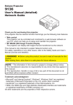
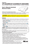
1.2 MY IMAGE (Still image Transfer) Display
Image files can be sent via the network, and up to 4 images can be stored in the
projector and displayed on screen one by one. (&39)
Transfer image data
Display image data ( 1 -
4
)
3
2. Equipment connection and network setting
2. Equipment connection and network setting
2.1 Required equipment preparation
The following equipment is required to connect the projector to your PC through
the network.
PC : 1) equipped with the network feature
2) installed a web browser software (&11)
LAN cable : CAT-5 or greater
NOTE • The system for using the projector's network function requires a
communication environment conforming 100Base-TX or 10Base-T.
4
2. Equipment connection and network setting
2.2 Manual network connection setting
2.2.1 Equipment connection
Connect the projector and PC with a LAN cable.
* Before connecting with an existing network, contact the network administrator.
Next, please check the PC setting as explained below.
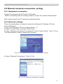
2.2.2 Network settings
This is the explanation of network connection settings for Windows® XP and
Internet Explorer®.
1) Log on to Windows® XP as an Administrator. (*)
2) Open “Control Panel” from the “Start” menu.
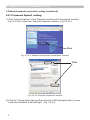
3) Open “Network and Internet Connections” in the “Control Panel”. (Fig. 2.2.2.a)
* An Administrator is able to access all functions.
Fig. 2.2.2.a “Network and Internet Connections” window
4) Open “Network Connections”. (Fig.2.2.2.b)
Fig. 2.2.2.b “Network Connections” window
5
2. Equipment connection and network setting
2.2 Manual network connection setting (continued)
5) Open the “Local Area Connection Properties” window you use for your network
device. (Fig. 2.2.2.c)
Fig. 2.2.2.c “Local Area Connection Properties” window
6) Set used protocol as “TCP/IP” and open the “Internet Protocol (TCP/IP)
Properties” window.
Fig. 2.2.2.d “Internet Protocol (TCP/IP) Properties” window
7) Set IP address, subnet mask and default gateway for the PC.
6
2. Equipment connection and network setting
2.2 Manual network connection setting (continued)
[About IP address]
■ Setting manually
The Network address portion of the PC's IP address should match the projector’s
address. And the entire IP address of the PC should be unique from all other
equipment in the same network, including the projector.
For example
The projector’s initial settings are as follows.
IP address: 192.168.1.10
Subnet mask: 255.255.255.0
(Network address: 192.168.1 in this case)
Therefore, specify PC’s IP address as follows.
IP address: 192.168.1.xxx (xxx shows decimal number.)
Subnet mask: 255.255.255.0
(Network address: 192.168.1 in this case)
Select a unique number between 1 and 254 for “xxx” which is not duplicated
by any other equipment. In this case, the projector has a “192.168.1.10” IP
address, specify from 1 to 254 except 10 for PC.
NOTE • “0.0.0.0” cannot be set to the IP address.
• The projector’s IP address can be changed by using the configuration utility
via a web browser. (&11)
• If the projector and PC exist in the same network (i.e. the network address is
common), the default gateway can be blank.
• When the projector and PC exist in different networks, the default gateway
setting is required. Contact the network administrator for details.
■ Setting automatically
When a DHCP server exists in network, the IP addresses to the projector and PC
can be set automatically.
* DHCP is an abbreviation for “Dynamic Host Configuration Protocol” and can
provide the required settings for the network like the IP address from the server
to the client. A server that has DHCP functions is called a DHCP server.
7
2. Equipment connection and network setting
2.2 Manual network connection setting (continued)
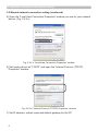
2.2.3 “Internet Option” setting
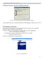
1) Click “Internet Options” in the “Network and Internet Connections” window
(Fig. 2.2.3.a) to open the “Internet Properties” window. (Fig.2.2.3.b)
Click
Fig. 2.2.3.a “Network and Internet Connections” window
Click
Fig. 2.2.3.b “Internet Properties” window
2) Click the “Connections” tab and then click the [LAN Settings] button to open
“Local Area Network (LAN) settings”. (Fig. 2.2.3.c)
8
2. Equipment connection and network setting
2.2 Manual network connection setting (continued)
Fig. 2.2.3.c “Local Area Network (LAN) Settings” window
3) Uncheck all boxes in “Local Area Network (LAN) Settings” window. (Fig. 2.2.3.c)
2.2.4 Check connection
Verify the PC and projector are connected properly. If they are not connected,
check the cable connections and settings.
1) Start browser in PC and specify following URL, then click “ ” button.
URL: http://(Projector IP address)/
For example, if projector IP address is 192.168.1.10, specify
URL: http://192.168.1.10/
2) If Fig. 2.2.4 appears, it was successful.
Fig. 2.2.4 “Logon Menu”
9
3. Management with Web browser software
3. Management with Web browser software
This projector is equipped with the following network functions by using web
browser software.
3.1 Configuring and Controlling the Projector via a Web Browser
You can change the settings of or control the projector via a network by using a
web browser from a PC that is connected to the same network.
(11)
3.2 E-mail Alerts
The projector can automatically send an alert to specified e-mail addresses when
the projector requires maintenance or has encountered an error.
(33)
3.3 Projector Management using SNMP
This projector is SNMP (Simple Network Management Protocol) compliant,
allowing you to monitor it from a remote location using SNMP software. In
addition, the projector is able to send failure & warning alerts to a specified PC.
(35)
3.4 Event Scheduling
You can schedule the projector to perform various functions on certain dates and
time.
(36)
3.5 MY IMAGE (Still Image Transfer) Display
The projector can display still images that are transferred via the network.
(39)
3.6 Command Control via the Network
The projector can be controlled using RS-232C commands over a network.
(41)
3.7 Controlling the external device via the projector (using the
NETWORK BRIDGE function)
The NETWORK BRIDGE function can control an external device as a network
terminal, via this projector from the computer. (46)
3.8 Batch-controlling multiple projectors (using the DAISY CHAIN
function)
The DAISY CHAIN function can simultaneously control multiple projectors
connected to a shared RS-232C bus, from the computer. (50)
10
3. Management with Web browser software
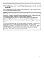
3.1 Configuring and controlling the projector via a web
browser
You can adjust or control the projector via a network from a web browser on a PC
that is connected to the same network.
NOTE • Internet Explorer® 5.5 or later is required.
• If JavaScript® is disabled in your web browser configuration, you must enable
JavaScript® in order to use the projector web pages properly. See the Help files
for your web browser for details on how to enable JavaScript®.
• You can communicate using SSL (Secure Socket Layer) if you are using
Windows® XP Service Pack 2 or earlier versions of Microsoft® Windows®.
Please specify “https://” when you enter the IP address of the projector on the
web browser. You can't communicate with the projector using SSL on Windows
Vista®.
• It is recommended that all web browser updates are installed. It is especially
recommended that all users running Internet Explorer® on a Microsoft®
Windows® version prior to Windows® XP Service Pack 2 install security update
Q832894 (MS04-004) or the web browser interface may not be displayed
correctly. And when using an earlier version of Internet Explorer®, during
operations the browser will log out after 50 seconds.
11
3. Management with Web browser software
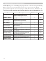
3.1 Configuring and controlling the projector via a web browser (continued)
When configuring or controlling the projector via a web browser, an ID and
password are required. There are two types of IDs, Administrator ID and User ID.
The following chart describes the differences between Administrator and User IDs.
Item
Description
Displays the projector’s current
Network Information
network configuration settings.
Administrator
User
√
√
Network Settings
Displays and configures network
settings.
√
N/A
Port Settings
Displays and configures
communication port settings.
√
N/A
Mail Settings
Displays and configures e-mail
addressing settings.
√
N/A
Alert Settings
Displays and configures failure &
warning alerts.
√
N/A
Schedule Settings
Displays and configures schedule
settings.
√
N/A
Date/Time Settings
Displays and configures the date and
time settings.
√
N/A
Security Settings
Displays and configures passwords
and other security settings.
√
N/A
Projector Control
Controls the projector.
√
√
Projector Status
Displays the current projector status.
√
√
Network Restart
Restarts the projector’s network
connection.
√
N/A
12
3. Management with Web browser software
3.1 Configuring and controlling the projector via a web browser (continued)
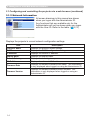
3.1.1 Logon
Refer to the following for configuring or controlling the projector via a web browser.
Example: If the IP address of the projector is set to 192.168.1.10:
1) Enter “http://192.168.1.10/” into the address
bar of the web browser and press “Enter”
key or click “ ” button. The screen in Fig.
3.1.1a will be displayed.
2) Enter your ID and password and click
[Logon].
Fig. 3.1.1 a “Logon Menu”
Below are the factory default settings for Administrator ID, User ID and passwords.
Item
ID
Password
Administrator
Administrator
<blank>
User
User
<blank>
If the logon is successful, the Fig. 3.1.1 b or the Fig. 3.1.1 c screen will be
displayed.
Main menu
Fig. 3.1.1 b “Logon with Administrator ID”
Main menu
Fig. 3.1.1 c “Logon with User ID”
3) Click the desired operation or configuration item on the main menu located on
the left-hand side of the screen.
13
3. Management with Web browser software
3.1 Configuring and controlling the projector via a web browser (continued)
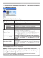
3.1.2 Network Information
All screen drawings in this manual are shown
when you logon with the Administrator ID.
Any functions that are available only for the
Administrator will not be shown when you logon
with the User ID. Refer to the table. (12,13)
Displays the projector’s current network configuration settings.
Item
Description
Projector Name
Displays the projector name settings.
DHCP
Displays the DHCP configuration settings.
IP Address
Displays the current IP address.
Subnet Mask
Displays the subnet mask.
Default Gateway
Displays the default gateway.
MAC Address
Displays the ethernet MAC address.
Firmware Date
Displays the network firmware time stamp. This information
is only displayed when logged on using an Administrator ID.
Firmware Version
Displays the network firmware version number. This
information is only displayed when logged on using an
Administrator ID.
14
3. Management with Web browser software
3.1 Configuring and controlling the projector via a web browser (continued)
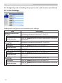
3.1.3 Network Settings
Displays and configures network settings.
Item
IP Configuration
Description
Configures network settings.
DHCP ON
Enables DHCP.
DHCP OFF
Disables DHCP.
IP Address
Configures the IP address when DHCP is disabled.
Subnet Mask
Configures the subnet mask when DHCP is disabled.
Default Gateway
Configures the default gateway when DHCP is disabled.
Projector Name
Configures the name of the projector.
The length of the Projector Name can be up to 64
alphanumeric characters. Only alphabetic letters, numbers
and the following symbols can be used. !"#$%&'()*+,./:;<=>?@[\]^_`{|}~ and space
sysLocation (SNMP)
Configures the location to be referred to when using SNMP.
The length of the sysLocation can be up to 255 alphanumeric
characters. Only numbers ‘0-9’ and alphabet ‘a-z’, ‘A-Z’ can
be used.
sysContact (SNMP)
Configures the contact information to be referred to when
using SNMP.
The length of the sysContact can be up to 255 alphanumeric
characters. Only numbers ‘0-9’ and alphabet ‘a-z’, ‘A-Z’ can
be used.
DNS Server Address
Configures the DNS server address.
Click the [Apply] button to save the settings.
NOTE • The new configuration settings are activated after restarting the
network connection. When the configuration settings are changed, you must
restart the network connection. You can restart the network connection by
clicking [Network Restart] on the main menu.
• If you connect the projector to an existing network, consult a network
administrator before setting server addresses.
15
3. Management with Web browser software
3.1 Configuring and controlling the projector via a web browser (continued)
3.1.4 Port Settings
Displays and configures communication port settings.
Item
Network Control Port1
(Port:23)
Description
Configures command control port 1 (Port:23).
Port open
Click the [Enable] check box to use port 23.
Authentication
Click the [Enable] check box when authentication is required
for this port.
Network Control Port2
(Port:9715)
Configures command control port 2 (Port:9715).
Port open
Click the [Enable] check box to use port 9715.
Authentication
Click the [Enable] check box when authentication is required
for this port.
PJLink TM Port (Port:4352) Configures the PJLink TM port (Port:4352).
Port open
Click the [Enable] check box to use port 4352.
Authentication
Click the [Enable] check box when authentication is required
for this port.
Image Transfer Port
(Port:9716)
16
Configures the image transfer port (Port:9716).
Port open
Click the [Enable] check box to use port 9716.
Authentication
Click the [Enable] check box when authentication is required
for this port.
3. Management with Web browser software
3.1 Configuring and controlling the projector via a web browser (continued)
Item
SNMP Port
Description
Configures the SNMP port.
Port open
Click the [Enable] check box to use SNMP.
Trap address
Configures the destination of the SNMP Trap in IP format.
• The address allows not only IP address but also domain
name if the valid DNS server is setup in the Network
Settings. The maximum length of host or domain name is up
to 255 characters.
SMTP Port
Port open
Network Bridge Port
Port Number
Daisy Chain Port
Port Number
Configures the SMTP port.
Click the [Enable] check box to use the e-mail function.
Configures the Bridge port number.
Input the port number. Any number between 1024 and 65535
can be set up. It is set to 9717 as the default setting.
Configures the Daisy Chain port number.
Input the port number. Any number between 1024 and 65535
can be set up. It is set to 9718 as the default setting.
Click the [Apply] button to save the settings.
NOTE • The new configuration settings are activated after restarting the
network connection. When the configuration settings are changed, you must
restart the network connection. You can restart the network connection by
clicking [Network Restart] on the main menu.
17
3. Management with Web browser software
3.1 Configuring and controlling the projector via a web browser (continued)
3.1.5 Mail Settings
Displays and configures e-mail addressing settings.
Item
Description
Send mail
Click the [Enable] check box to use the e-mail function.
Configure the conditions for sending e-mail under the Alert
Settings.
SMTP Server Address
Configures the address of the mail server in IP format.
• The address allows not only IP address but also domain
name if the valid DNS server is setup in the Network
Settings. The maximum length of host or domain name is up
to 255 characters.
Sender E-mail address
Configures the sender e-mail address.
The length of the sender e-mail address can be up to 255
alphanumeric characters.
Configures the e-mail address of up to five recipients. You
can also specify [TO] or [CC] for each address. The length of
Recipient E-mail address
the recipient e-mail address can be up to 255 alphanumeric
characters.
Click the [Apply] button to save the settings.
NOTE • You can confirm whether the mail settings work correctly using [Send
Test Mail] button. Please enable Send mail setting before clicking [Send Test
Mail].
• If you connect the projector to an existing network, consult a network
administrator before setting server addresses.
18
3. Management with Web browser software
3.1 Configuring and controlling the projector via a web browser (continued)
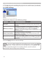
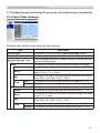
3.1.6 Alert Settings
Displays and configures failure & alert settings.
Alert Item
Description
Cover Error
The lamp cover has not been properly closed.
Fan Error
The cooling fan is not operating.
Lamp Error
The lamp does not light, and the interior portion may have
become overheated.
Temp Error
The internal temperature of the projector may have become
overheated.
Air Flow Error
The internal temperature is rising.
Cold Error
The internal temperature of the projector may have become
overcooled.
Filter Error
The filter time is done.
Shutter Error
The shutter is not working correctly.
Other Error
Other error.
If displaying this error, please contact your dealer.
Schedule Execution
Error
Schedule Execution error. (21)
Lamp Time Alarm
Lamp time over Alarm Time setting.
Filter Time Alarm
Filter time over Alarm Time setting.
Transition Detector
Alarm
Transition Detector Alarm. (OPTION menu in the User’s
Manual (detailed) – Operating Guide)
Cold Start
The Power switch is turned on.
(Off → standby mode)
Authentication Failure
The SNMP access is detected from the invalid SNMP
community.
Refer to “Troubleshooting” in the User’s Manual (detailed) – Operating Guide for
additional details about the Error except Other Error and Schedule Execution Error.
19
3. Management with Web browser software
3.1 Configuring and controlling the projector via a web browser (continued)
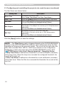
The Alert Items are shown below.
Setting Item
Description
Alarm Time
Configures the time to alert.
(Only Lamp Time Alarm and Filter Time Alarm.)
SNMP Trap
Click the [Enable] check box to enable SNMP Trap alerts.
Send Mail
Click the [Enable] check box to enable e-mail alerts.
(Except Cold Start and Authentication Failure.)
Mail Subject
Configures the subject line of the e-mail to be sent.
The length of the subject line can be up to 100 alphanumeric
characters.
(Except Cold Start and Authentication Failure.)
Mail Text
Configures the text of the e-mail to be sent.
The length of the text can be up to 1024 alphanumeric
characters.
(Except Cold Start and Authentication Failure.)
Click the [Apply] button to save the settings.
NOTE • The Filter Error e-mail is triggered based on the FILTER MESSAGE
settings in the OPTION>SERVICE submenu which defines the when the filter
message will display on the projector screen. The e-mail will be sent when the
filter timer exceeds 2000, 5000 or 10000 hours based on this configuration.
Notification e-mails will not be sent if the FILTER MESSAGE is set to OFF.
(OPTION menu in the User’s Manual (detailed) – Operating Guide)
• Lamp Time Alarm is defined as a threshold for e-mail notification (reminder)
of the lamp timer. When the lamp hour exceeds the configured threshold, the
e-mail will be sent out.
• Filter Time Alarm is defined as a threshold for e-mail notification (reminder)
of the filter timer. When the filter hour exceeds this threshold, the e-mail will be
sent out.
20
3. Management with Web browser software
3.1 Configuring and controlling the projector via a web browser (continued)
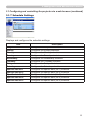
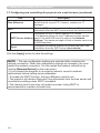
3.1.7 Schedule Settings
Displays and configures the schedule settings.
Item
Description
Daily
Configures the daily schedule.
Sunday
Configures the Sunday schedule.
Monday
Configures the Monday schedule.
Tuesday
Configures the Tuesday schedule.
Wednesday
Configures the Wednesday schedule.
Thursday
Configures the Thursday schedule.
Friday
Configures the Friday schedule.
Saturday
Configures the Saturday schedule.
Specific date No.1
Configures the specific date (No.1) schedule.
Specific date No.2
Configures the specific date (No.2) schedule.
Specific date No.3
Configures the specific date (No.3) schedule.
Specific date No.4
Configures the specific date (No.4) schedule.
Specific date No.5
Configures the specific date (No.5) schedule.
21
3. Management with Web browser software
3.1 Configuring and controlling the projector via a web browser (continued)
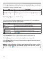
The schedule settings are shown below.
Item
Description
Schedule
Click the [Enable] check box to enable the schedule.
Date (Month/Day)
Configures the month and date.
This item appears only when Specific date (No. 1-5) is
selected.
Click the [Apply] button to save the settings.
The current event settings are displayed on the schedule list. To add additional
functions and events, set the following items.
Item
Description
Time
Configures the time to execute commands.
Command
[Parameter]
Configures the commands to be executed.
Power
Configures the parameters for power control.
Input Source
Configures the parameters for input switching.
Display Image
Configures the parameters for display of transfered image
data (39).
Click the [Register] button to add new commands to the schedule list.
Click the [Delete] button to delete commands from the schedule list.
Click the [Reset] button to delete all commands and reset the schedule settings
from the schedule list.
NOTE • After the projector is moved, check the date and time settings for the
projector before configuring the schedules. A strong shock can make the date
and time settings (23) change.
22
3. Management with Web browser software
3.1 Configuring and controlling the projector via a web browser (continued)
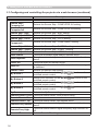
3.1.8 Date/Time Settings
Displays and configures the date and time settings.
Item
Description
Current Date
Configures the current date in year/month/day format.
Current Time
Configures the current time in hour:minute:second format.
Daylight Savings Time
Click the [ON] check box to enable daylight savings time and
set the following items.
Start
Configures the date and time daylight savings time begins.
Month
Configures the month daylight savings time begins (1~12).
Week
Configures the week of the month daylight savings time
begins (First, 2, 3, 4, Last).
Day
Configures the day of the week daylight savings time begins
(Sun, Mon, Tue, Wed, Thu, Fri, Sat).
Time
hour
Configures the hour daylight savings time begins (0 ~ 23).
minute
Configures the minute daylight savings time begins (0 ~ 59).
End
Configures the date and time daylight savings time ends.
Month
Configures the month daylight savings time ends (1 ~ 12).
Week
Configures the week of the month daylight savings time ends
(First, 2, 3, 4, Last).
Day
Configures the day of the week daylight savings time ends
(Sun, Mon, Tue, Wed, Thu, Fri, Sat).
Time
hour
Configures the hour daylight savings time ends (0 ~ 23).
minute
Configures the minute daylight savings time ends (0 ~ 59).
23
3. Management with Web browser software
3.1 Configuring and controlling the projector via a web browser (continued)
Item
Description
Time difference
Configures the time difference. Set the same time difference
as the one set on your PC. If unsure, consult your IT
manager.
SNTP
Click the [ON] check box to retrieve Date and Time
information from the SNTP server and set the following items.
Configures the SNTP server address in IP format.
• The address allows not only IP address but also domain
SNTP Server Address name if the valid DNS server is setup in the Network
Settings. The maximum length of host or domain name is up
to 255 characters.
Cycle
Configures the interval at which to retrieve Date and Time
information from the SNTP server (hour:minute).
Click the [Apply] button to save the settings.
NOTE • The new configuration settings are activated after restarting the
network connection. When the configuration settings are changed, you must
restart the network connection. You can restart the network connection by
clicking [Network Restart] on the main menu.
• If you connect the projector to an existing network, consult a network
administrator before setting server addresses.
• To enable the SNTP function, the time difference must be set.
• The projector will retrieve Date and Time information from the time server and
override time settings when SNTP is enabled.
• The internal clock’s time may not remain accurate. Using SNTP is
recommended to maintain accurate time.
24
3. Management with Web browser software
3.1 Configuring and controlling the projector via a web browser (continued)
3.1.9 Security Settings
Displays and configures passwords and other security settings.
Item
Administrator authority
Description
Configures the Administrator ID and password.
Administrator ID
Configures the Administrator ID.
The length of the text can be up to 32 alphanumeric
characters.
Administrator
Password
Configures the Administrator password.
The length of the text can be up to 255 alphanumeric
characters.
Re-enter
Administrator
Password
Re-enter the above password for verification.
User authority
Configures the User ID and password.
User ID
Configures the User ID.
The length of the text can be up to 32 alphanumeric
characters.
User Password
Configures the User password.
The length of the text can be up to 255 alphanumeric
characters.
Re-enter User
Password
Re-enter the above password for verification.
25
3. Management with Web browser software
3.1 Configuring and controlling the projector via a web browser (continued)
Item
Network Control
Description
Configures the Authentication password for the command
control.
Authentication
Password
Configures the Authentication password. The length of the
text can be up to 32 alphanumeric characters.
Re-enter
Authentication
Password
Re-enter the above password for verification.
SNMP
Community name
Configures the community name if SNMP is used.
Configures the community name. The length of the text can
be up to 64 alphanumeric characters.
Click the [Apply] button to save the settings.
NOTE • The new configuration settings are activated after restarting the
network connection. When the configuration settings are changed, you must
restart the network connection. You can restart the network connection by
clicking [Network Restart] on the main menu.
• Only numbers ‘0-9’ and alphabet ‘a-z’, ‘A-Z’ can be used.
26
3. Management with Web browser software
3.1 Configuring and controlling the projector via a web browser (continued)
3.1.10 Projector Control
The items shown in the table below can be
performed using the Projector Control menu.
Select an item using the up and down arrow keys
on the PC.
Most of the items have a submenu. Refer to the
table below for details.
NOTE • The setting value may not match the actual value if the user changes
the value manually. In that case, please refresh the page by clicking the
[Refresh] button.
Controls the projector.
Item
Main
Power
Input Source
Picture Mode
Blank On/Off
Freeze
Magnify
Template
Shutter
Zoom
Focus
Lens Shift V
Lens Shift H
Lens Memory
P by P
P by P Left Source
P by P Right Source
P by P Main Area
MY Image
MY Image Delete
Picture
Brightness
Contrast
Description
Turns the power on/off.
Selects the input source.
Selects the picture mode setting.
Turns Blank on/off.
Turns Freeze on/off.
Controls the magnify setting.
In some input signal sources, it might stop “Magnify” even
though it does not reach to maximum setting value.
Turns template on/off.
Open / close the shutter.
Adjusts the zoom setting.
Adjusts the focus setting.
Adjusts the vertical lens shift.
Adjusts the horizontal lens shift.
Saves / Loads the Lens Memory data.
Turns the P by P on / off.
Selects the P by P Left Source setting.
Selects the P by P Right Source setting.
Selects the P by P Main Area Source setting.
Select MY IMAGE data.
Delete MY IMAGE data.
Adjusts the brightness setting.
Adjusts the contrast setting.
27
3. Management with Web browser software
3.1 Configuring and controlling the projector via a web browser (continued)
Item
Picture (continue)
Gamma
Color Temp
Color
Tint
Sharpness
Active Iris
Active Iris - Manual
MyMemory Save
MyMemory Recall
Image
Aspect
Over Scan
V Position
H Position
H Phase
H Size
Auto Adjust Execute
Input
Progressive
Video NR
3D-YCS
Color Space
Component
Video 1 Format
Video 2 Format
S-Video Format
HDMI Format
DVI-D Format
HDMI Range
DVI-D Range
Computer in 1
Computer in 2
BNC
Frame LockComputer in 1
Frame LockComputer in 2
Frame Lock-BNC
Frame Lock-HDMI
Frame Lock-DVI-D
28
Description
Selects the gamma setting.
Selects the color temperature setting.
Adjusts the color setting.
Adjusts the tint setting.
Adjusts the sharpness setting.
Selects the active iris setting.
Adjusts the active iris - manual setting.
Saves the MyMemory data.
Recalls the MyMemory data.
Selects the aspect setting.
Adjusts the over scan setting.
Adjusts the vertical position.
Adjusts the horizontal position.
Adjusts the horizontal phase.
Adjusts the horizontal size.
Performs the automatic adjustment.
Selects the progressive setting.
Selects the video noise reduction setting.
Selects the 3D-YCS setting.
Selects the color space.
Selects the Component port setting.
Selects the video 1 format setting.
Selects the video 2 format setting.
Selects the s-video format setting.
Selects the HDMI format setting.
Selects the DVI-D format setting.
Selects the HDMI range setting.
Selects the DVI-D range setting.
Selects the Computer in 1 input signal type.
Selects the Computer in 2 input signal type.
Selects the BNC input signal type.
Turns the FRAME LOCK-COMPUTER IN1 function on/off.
Turns the FRAME LOCK-COMPUTER IN2 function on/off.
Turns the FRAME LOCK-BNC function on/off.
Turns the FRAME LOCK-HDMI function on/off.
Turns the FRAME LOCK-DVI-D function on/off.
3. Management with Web browser software
3.1 Configuring and controlling the projector via a web browser (continued)
Item
Setup
Auto Keystone
Execute
Keystone V
Keystone H
Eco Mode
Mirror
Monitor Out Computer in 1
Monitor Out Computer in 2
Monitor Out - BNC
Monitor Out - HDMI
Monitor Out - DVI-D
Monitor Out Component
Monitor Out - S-Video
Monitor Out - Video 1
Monitor Out - Video 2
Monitor Out - Standby
Screen
Language
Menu Position V
Menu Position H
Blank
Startup
MyScreen Lock
Message
Template
C.C. - Display
C.C. - Mode
C.C. - Channel
Description
Performs the automatic keystone distortion setting.
Adjusts the vertical keystone distortion setting.
Adjusts the horizontal keystone distortion setting.
Selects the eco mode.
Selects the mirror status.
Assigns the MONITOR OUT when the COMPUTER IN1
input port is selected.
Assigns the MONITOR OUT when the COMPUTER IN2
input port is selected.
Assigns the MONITOR OUT when the BNC input port is
selected.
Assigns the MONITOR OUT when the HDMI input port is
selected.
Assigns the MONITOR OUT when the DVI-D input port is
selected.
Assigns the MONITOR OUT when the Component input port
is selected.
Assigns the MONITOR OUT when the S-VIDEO input port is
selected.
Assigns the MONITOR OUT when the VIDEO 1 input port is
selected.
Assigns the MONITOR OUT when the VIDEO 2 input port is
selected.
Assigns the MONITOR OUT in the standby mode.
Selects the language for the OSD.
Adjusts the vertical Menu position.
Adjusts the horizontal Menu position.
Selects the Blank mode.
Selects the startup screen mode.
Turns MyScreen lock function on/off.
Turns the message function on/off.
Selects the template setting.
Selects Closed Caption DISPLAY setting.
Selects Closed Caption MODE setting.
Selects Closed Caption CHANNEL setting.
29
3. Management with Web browser software
3.1 Configuring and controlling the projector via a web browser (continued)
Item
Option
Source Skip Computer in1
Source Skip Computer in2
Source Skip - BNC
Source Skip - HDMI
Source Skip - DVI-D
Source Skip Component
Source Skip - S-Video
Source Skip - Video 1
Source Skip - Video 2
Auto Search
Description
Selects the Source Skip - COMPUTER IN1 setting.
Selects the Source Skip - COMPUTER IN2 setting.
Selects the Source Skip - BNC setting.
Selects the Source Skip - HDMI setting.
Selects the Source Skip - DVI-D setting.
Selects the Source Skip - COMPONENT setting.
Selects the Source Skip - S-VIDEO setting.
Selects the Source Skip - VIDEO 1 setting.
Selects the Source Skip - VIDEO 2 setting.
Turns the automatic signal search function on/off.
Turns the automatic keystone distortion correction function
Auto Keystone
on/off.
Direct On
Turns the direct on function on/off.
Configures the timer to shut off the projector when no signal
Auto Off
is detected.
Shutter Timer
Selects the shutter timer setting.
Assigns the functions for the MY BUTTON1 button on the
My Button-1
included remote control.
Assigns the functions for the MY BUTTON2 button on the
My Button-2
included remote control.
Assigns the functions for the MY BUTTON3 button on the
My Button-3
included remote control.
Assigns the functions for the MY BUTTON4 button on the
My Button-4
included remote control.
My Source
Selects the My Source setting.
Remote Receiv. Front Turns the remote receiv. front function on/off.
Remote Receiv. Rear Turns the remote receiv. rear function on/off.
Remote Receiv. Top
Turns the remote receiv. top function on/off.
Turns the remote control signal frequency nomal function
Remote Freq. Normal
on/off.
Turns the remote control signal frequency high function on/
Remote Freq. High
off.
Remote ID
Selects Remote ID setting.
30
3. Management with Web browser software
3.1 Configuring and controlling the projector via a web browser (continued)
3.1.11 Projector Status
Displays the current projector status.
Item
Description
Error Status
Displays the current error status
Lamp Time
Displays the usage time for the current lamp.
Filter Time
Displays the usage time for the current filter.
Power Status
Displays the current power status.
Input Status
Displays the current input signal source.
Blank On/Off
Displays the current Blank on/off status.
Freeze
Displays the current Freeze status.
Shutter
Displays the current Shutter status.
31
3. Management with Web browser software
3.1 Configuring and controlling the projector via a web browser (continued)
3.1.12 Network Restart
Restarts the projector’s network connection.
Item
Restart
Description
Restarts the projector’s network connection in order to
activate new configuration settings.
NOTE • Restarting requires you to re-log on in order to further control or
configure the projector via a web browser. Wait 1 minute or more after clicking
[Restart] button to log on again.
• The Logon menu (13) is displayed after restarting the projector’s network
connection if the DHCP is set to ON.
3.1.13 Logoff
When [Logoff] is clicked, the Logon menu is displayed. (13)
32
3. Management with Web browser software
3.2 E-mail Alerts
The projector can automatically send an alert message to the specified e-mail
addresses when the projector detects an error or a defined maintenance
condition.
NOTE • Up to five e-mail addresses can be specified.
• The projector may be not able to send an e-mail if the projector suddenly
loses power.
Mail Settings (18)
To use the projector’s e-mail alert function, please configure the following items
through a web browser.
Example: If the IP address of the projector is set to 192.168.1.10:
1) Enter “http://192.168.1.10/” into the address bar of the web browser.
2) Enter the Administrator ID and password and click [Logon].
3) Click the [Port Settings] on the main menu.
4) Click the [Enable] check box to open the SMTP Port.
5) Click the [Apply] button to save the settings.
NOTE • A Network Restart is required after the SMTP Port configuration
settings have changed. Click the [Network Restart] and configure the following
items.
6) Click the [Mail Settings] and configure each item. Refer to the item 3.1.5 Mail
Settings (18) for further information.
7) Click the [Apply] button to save the settings.
NOTE • Click the [Send Test Mail] button in [Mail Settings] to confirm that
the e-mail settings are correct. The following mail will be delivered to the
specified addresses.
Subject line
Text
:Test Mail
:Send Test Mail
Date
Time
IP Address
MAC Address
<Projector name>
<Testing date>
<Testing time>
<Projector IP address>
<Projector MAC address>
33
3. Management with Web browser software
3.2 E-mail Alerts (continued)
8) Click the [Alert Settings] on the main menu to configure the E-mail Alerts
settings.
9) S
elect and configure each alert item. Refer to the item 3.1.6 Alert Settings (19)
for further information.
10) Click the [Apply] button to save the settings.
Failure/Warning e-mails are formatted as follows:
Subject line : <Mail title>
<Projector name>
Text
: <Mail text>
Date
<Failure/Warning date>
Time
<Failure/Warning time>
IP Address
<Projector IP address>
MAC Address <Projector MAC address>
34
3. Management with Web browser software
3.3 Projector Management using SNMP
The SNMP (Simple Network Management Protocol) can manage projector
failure and warning information from the computer on the network. The SNMP
management software must be used on the computer to use this function.
NOTE • It is recommended that SNMP functions be carried out by a network
administrator.
• SNMP management software must be installed on the computer to monitor
the projector via SNMP.
SNMP Settings (16)
Configure the following items via a web browser to use SNMP.
Example: If the IP address of the projector is set to 192.168.1.10:
1) Enter “http://192.168.1.10/” into the address bar of the web browser.
2) Enter the Administrator ID and Password and click [Logon].
3) Click the [Port Settings] on the main menu.
4) Click the [Enable] check box to open the SNMP Port. Set the IP address to
send the SNMP trap to when a Failure/Warning occurs.
NOTE • A Network Restart is required after the SNMP Port configuration
settings have been changed. Click the [Network Restart] and configure the
following items.
5) Click the [Security Settings] on the main menu.
6) Click the [SNMP] and set the community name on the screen that is displayed.
NOTE • A Network Restart is required after the Community name has been
changed. Click the [Network Restart] and configure the following items.
7) Configure the settings for Trap transmission of Failures/Warnings. Click the
[Alert Settings] on the main menu and select the Failure/Warning item to be
configured.
8) Click the [Enable] check box to send out the SNMP trap for Failures/Warnings.
Clear the [Enable] check box when SNMP trap transmission is not required.
9) Click the [Apply] button to save the settings.
35
3. Management with Web browser software
3.4 Event Scheduling
The scheduling function can be used to setup scheduled events including
powering the projector on and off. This enables the projector to be “self-managing."
NOTE • You can schedule the following control events: Power ON/OFF, Input
Source and Transferred Image Display.
• The power on / off event has the lowest priority among the all events that are
defined to occur simultaneously.
• There are 3 types of Scheduling, 1) daily 2) weekly 3) specific date. (21)
• The priority for scheduled events is as follows 1) specific date 2) weekly 3)
daily.
• Up to five specific dates are available for scheduled events. Priority is given to
those with the lower numbers when more than one event has been scheduled
for the same date and time (e.g., ‘Specific date No. 1’ has priority over ‘Specific
date No. 2’ and so on.
• Be sure to set the date and time before enabling scheduled events. (23)
36
3. Management with Web browser software
3.4 Event Scheduling (continued)
Schedule Settings (21)
Schedule settings can be configured from a web browser.
Example: If the IP address of the projector is set to 192.168.1.10:
1) Enter “http://192.168.1.10/” into the address bar of the web browser.
2) Enter the Administrator ID and password and click [Logon].
3) Click the [Schedule Settings] on the main menu and select the required
schedule item. For example, if you want to perform the command every Sunday,
please select [Sunday].
4) Click the [Enable] check box to enable scheduling.
5) Enter the date (month/day) for specific date scheduling.
6) Click the [Apply] button to save the settings.
7) After configuring the time, command and parameters, click [Register] to add
the new event.
8) Click the [Delete] button when you want to delete a schedule.
There are three types of scheduling.
1) Daily: Perform the specified operation at a specified time every day.
2) Sunday ~ Saturday: Perform the specified operation at the specified time on a
specified day of the week.
3) Specific date: Perform the specified operation on the specified date and time.
NOTE • In Standby mode, the power indicator will flash green for approx. 3
seconds when at least 1 “Power ON” schedule is saved.
• When the schedule function is used, the power cord must be connected to
the projector and the outlet and the power switch must be turned on, [ | ]. The
schedule function does not work when the power switch is turned off, [O] or
the breaker in a room is tripped. The power indicator will light orange or green
when the projector is receiving the power.
37
3. Management with Web browser software
3.4 Event Scheduling (continued)
Date/Time Settings (23)
The Date/Time setting can be adjusted via a web browser.
Example: If the IP address of the projector is set to 192.168.1.10:
1) Enter “http://192.168.1.10/” into the address bar of the web browser. Enter the
Administrator ID and Password and click [Logon].
2) Click the [Date/Time Settings] on the main menu and configure each item.
Refer to the item 3.1.8 Data/Time Settings for further information.
3) Click the [Apply] button to save the settings.
NOTE • A Network Restart is required after the Daylight Savings Time or
SNTP configuration settings have been changed.
• If the clock loses time even when the date and time have been set correctly,
the battery for the built in clock may be dead. Replace the battery by following
the “Internal clock battery” section of the User's Manual (concise).
• The internal clock’s time may not remain accurate. Using SNTP is
recommended to maintain accurate time.
38
3. Management with Web browser software
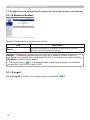
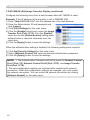
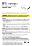
3.5 MY IMAGE (Still Image Transfer) Display
The projector can display still images that are transferred via the network.
Transfer image data
Display image data ( 1 -
4
)
Fig. 3.5 Still Image Transfer
MY IMAGE transmission requires a proprietary application for your PC. You can
download it from the InFocus website (www.infocus.com/support). Refer to the
application manual for instructions.
To display the transferred image, select the MY IMAGE item in the NETWORK
menu. For more information, please see the description of the MY IMAGE item
of the NETWORK menu. ( NETWORK menu in User’s Manual (detailed) –
Operating Guide)
NOTE • A maximum of 4 images can be sent.
• The image file also can be displayed by using the schedule function from
the web browser. Refer to the item 3.4 Event Scheduling (36) for more
information.
39
3. Management with Web browser software
3.5 M
Y IMAGE (Still Image Transfer) Display (continued)
Configure the following items from a web browser when MY IMAGE is used.
Example: If the IP address of the projector is set to 192.168.1.10:
1) Enter "http://192.168.1.10/" into the address bar of the web browser.
2) Enter the Administrator ID and password and
click [Logon].
3) Click [Port Settings] on the main menu.
4) Click the [Enable] check box to open the Image
Transfer Port (Port: 9716). Click the [Enable]
check box for the [Authentication] setting when
authentication is required, otherwise clear the
check box.
5) Click the [Apply] button to save the settings.
When the authentication setting is enabled, the following settings are required.
6) Click the [Security Settings] on the main menu.
7) Select [Network Control] and enter the desired authentication password.
8) Click the [Apply] button to save the settings.
NOTE • The Authentication Password will be the same for Network Control
Port1 (Port: 23), Network Control Port2 (Port: 9715), and Image Transfer
Port (Port: 9716).
• The new configuration settings are activated after restarting the network
connection. When the configuration settings are changed, you must restart
the network connection. You can restart the network connection by clicking
[Network Restart] on the main menu.
40
3. Management with Web browser software
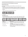
3.6 Command Control via the Network
You can configure and control the projector via the network using RS-232C
commands.
Communication Port
The following two ports are assigned for the command control.
TCP #23
TCP #9715
NOTE • Command control is not available via the communication port (TCP
#9716) (16) that is used for the MY IMAGE transmission function.
Command Control Settings (16)
Configure the following items from a web browser when command control is used.
Example: If the IP address of the projector is set to 192.168.1.10:
1) Enter “http://192.168.1.10/” into the address bar of the web browser.
2) Enter the Administrator ID and password and click [Logon].
3) Click the [Port Settings] on the main menu.
4) Click the [Enable] check box to open Network Control Port1 (Port: 23) to
use TCP #23. Click the [Enable] check box for [Authentication] setting when
authentication is required, otherwise clear the check box.
5) Click the [Enable] check box to open Network Control Port2 (Port: 9715)
to use TCP #9715. Click the [Enable] check box for [Authentication] setting
when authentication is required, otherwise clear the check box.
6) Click the [Apply] button to save the settings.
41
3. Management with Web browser software
3.6 Command Control via the Network (continued)
When the authentication setting is enabled, the following settings are required.
(25)
7) Click the [Security Settings] on the main menu.
8) Click the [Network Control] and enter the desired authentication password.
* See NOTE.
9) Click the [Apply] button to save the settings.
NOTE • The Authentication Password will be the same for Network Control
Port1 (Port: 23), Network Control Port2 (Port: 9715), and Image Transfer
Port (Port: 9716).
• The new configuration settings are activated after restarting the network
connection. When the configuration settings are changed, you must restart
the network connection. You can restart the network connection by clicking
[Network Restart] on the main menu.
42
3. Management with Web browser software
3.6 Command Control via the Network (continued)
Command Format
Command formats differ among the different communication ports.
● TCP #23
You can use the RS-232C commands without any changes. The reply data
format is the same as the RS-232C commands. However, the following reply
will be sent back in the event of authentication failure when authentication is
enabled.
<Reply in the event of an authentication error>
Reply
0x1F
Error code
0x04
0x00
● TCP #9715
Send Data format
The following formatting is added to the header (0x02), Data length (0x0D),
checksum (1byte) and Connection ID (1 byte) of the RS-232C commands.
Header
Data length
RS-232C command
Check Sum
Connection
ID
0x02
0x0D
13 bytes
1 byte
1 byte
Header
→ 0x02, Fixed
Data length
→ RS-232C commands byte length (0x0D, Fixed)
RS-232C commands →RS-232C commands that start with 0xBE 0xEF
(13 bytes)
Check Sum
→This is the value to make zero on the addition of the
lower 8 bits from the header to the checksum.
Connection ID
→Random value from 0 to 255 (This value is attached
to the reply data)
43
3. Management with Web browser software
3.6 Command Control via the Network (continued)
Reply Data format
The connection ID (the data is same as the connection ID data on the sending
data format) is attached to the RS-232C commands reply data.
<ACK reply>
Reply
Connection
ID
0x06
1 byte
<NAK reply>
Reply
Connection
ID
0x15
1 byte
<Error reply>
Reply
Error code
Connection
ID
0x1C
2 bytes
1 byte
Reply
Data
Connection
ID
0x1D
2 bytes
1 byte
Reply
Status code
Connection
ID
0x1F
2 bytes
1 byte
<Data reply>
<Projector busy reply>
<Authentication error reply>
44
Reply
Authentication
Error code
0x1F
0x04
0x00
Connection
ID
1 byte
3. Management with Web browser software
3.6 Command Control via the Network (continued)
Automatic Connection Break
The TCP connection will automatically disconnect after 30 seconds with no
communication.
Authentication
The projector does not accept commands without authentication success
when authentication is enabled. The projector uses a challenge response type
authentication with an MD5 (Message Digest 5) algorithm.
When the projector is using a LAN, a random 8 bytes will be returned if
authentication is enabled. Combine the 8 bytes received and the Authentication
Password and use this data with the MD5 algorithm. Add this in front of the send
commands.
For example, if the Authentication Password is set to “password” and the random
8 bytes are “a572f60c”.
1) Select the projector.
2) Receive the random 8 bytes “a572f60c” from the projector.
3) Combine the random 8 bytes “a572f60c” and the Authentication Password
“password” to create “a572f60cpassword”.
4) Use this combination “a572f60cpassword” with the MD5 algorithm.
It will become “e3d97429adffa11bce1f7275813d4bde”.
5) Add this “e3d97429adffa11bce1f7275813d4bde” in front of the commands
and send the data.
Send “e3d97429adffa11bce1f7275813d4bde”+command.
6) When the sending data is correct, the command will be performed and the
reply data will be returned. Otherwise, an authentication error will be returned.
NOTE • Regarding the second and subsequent commands, the authentication
data can be omitted when using the same connection.
45
3. Management with Web browser software
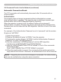
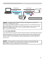
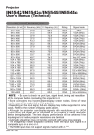
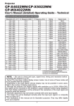
3.7 Controlling the external device via the projector
(using the NETWORK BRIDGE function)
This projector is equipped with the NETWORK BRIDGE function to perform
mutual conversion of a network protocol and a serial interface.
Using the NETWORK BRIDGE function, a computer that is connected with
this projector by Ethernet communication can control an external device that is
connected with this projector by RS-232C communication as a network terminal.
TCP/IP data
Ethernet
LAN cable
Computer
LAN port
Protocol change
Serial data
RS-232C
RS-232C cable
External device
CONTROL OUT port
3.7.1 Connecting devices
1) Connect the projector’s LAN port and the computer’s LAN port with a LAN
cable, for Ethernet communication.
2) Connect the projector’s CONTROL OUT port and the device’s RS-232C port
with an RS-232C cable, for RS-232C communication.
NOTE • Before connecting the devices, read the manuals for the devices to
ensure the connection.
For RS-232C connection, check the specifications of each port and use a
suitable cable. (Operating Guide - Technical - Connection to the ports)
46
3. Management with Web browser software
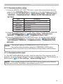
3.7.2 Communication setup
1) Using the SERIAL OUT SETTING menu, select the proper baud rate and
parity for the CONTROL OUT port, according to the specification of the RS232C port of the connected device. (Operating Guide - OPTION menu
- SERVICE – COMMUNICATION – SERIAL IN SETTING/SERIAL OUT
SETTING)
Item
BAUD RATE
PARITY
Condition
4800bps/9600bps/19200bps/38400bps
NONE/ODD/EVEN
Data length
8 bit (fixed)
Start bit
1 bit (fixed)
Stop bit
1 bit (fixed)
2) Using the COMMUNICATION TYPE menu, select the NETWORK BRIDGE
for the CONTROL OUT port. (Operating Guide - OPTION menu SERVICE – COMMUNICATION – COMMUNICATION TYPE)
3) Using the COMMUNICATION METHOD menu, set up the proper method
for the CONTROL OUT port, according to your use. (Operating Guide
- OPTION menu - SERVICE – COMMUNICATION – COMMUNICATION
METHOD)
NOTE • The default setting of COMMUNICATION TYPE is OFF.
• Set up the communication using the COMMUNICATION menu.
Remember that an incorrect setup could cause communication malfunctions.
3.7.3 Communication port
For the NETWORK BRIDGE function, send the data from the computer to the
projector using the Network Bridge Port that is configured in the “Port Settings” of
web browser. (3.1.4 Port settings – Network Bridge Port)
NOTE • Any number between 1024 and 65535 can be used as the Network
Bridge port number. By default, the number is set to 9717.
47
3. Management with Web browser software
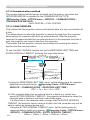
3.7.4 Communication method
The communication method can be selected from the menus, only when the
NETWORK BRIDGE is selected for the COMMUNICATION TYPE.
(Operating Guide - OPTION menu - SERVICE – COMMUNICATION –
TRANSMISSION METHOD)
HALF-DUPLEX FULL-DUPLEX
3.7.4.1 HALF-DUPLEX
This method lets the projector receive and transmit data, but only one direction at
a time.
The method does not allow the projector to receive the data from the computer
while waiting for response data from an external device. After the projector
receives the response data from an external device or the response limit time is
past, the projector can receive data from the computer.
That means that the projector controls transmitting and receiving the data to
synchronize the communication.
To use the HALF-DUPLEX method, set up the RESPONSE LIMIT TIME and
BYTES INTERVAL TIMEOUT, following the instruction below.
TCP/IP data
Computer
Ethernet
LAN cable
Protocol change
Serial data
RS-232C
RS-232C cable
External device
Transmitting data
Transmitting data
Discarding data
Response data
Response limit
time
Response data
Transmitting data
1) Using the RESPONSE LIMIT TIME menu, set the waiting time for response
data from an external device. (Operating Guide - OPTION menu SERVICE – COMMUNICATION – RESPONSE LIMIT TIME )
OFF 1s 2s 3s ( OFF)
2) If the response data from an external device is blank in a certain time
period (BYTES INTERVAL TIMEOUT), the projector will determine when the
response data is finished, and start to send data again.
If a blank time in the response data is longer than the BYTES INTERVAL
TIMEOUT, the projector cannot receive all data, then the computer may not be
able to control an external device well.
U
sing the BYTES INTERVAL TIMEOUT menu, set the waiting time for
response data to match your system. (Operating Guide - OPTION menu SERVICE – COMMUNICATION – BYTES INTERVAL TIMEOUT)
50ms 100ms 150ms 200ms ( 50ms)
48
3. Management with Web browser software
[1][2][3][4][5]
LAN cable
Computer
[6][7][8]
[1][2][3][4][5]
Control cable
[6][7][8]
[9][0]
External device
t
T (: bytes interval timeout) < t
NOTE • Using the HALF-DUPLEX method, the projector can send out a
maximum of 254 bytes at once.
• If you do not need to monitor the response data from an external device and
the RESPONSE LIMIT TIME is set to OFF, the projector can receive the data
from the computer and send it out to an external device continuously.
OFF is the default setting.
3.7.4.2 FULL-DUPLEX
This method lets the projector communicate both ways, transmitting and receiving
data simultaneously, without monitoring response data from an external device.
Using this method, the computer and an external device will send data without
synchronization. If the information must be synchronized, set the computer to
synchronize.
NOTE • If the computer controls are set to synchronize transmitting and
receiving of the data, it may not be able to control an external device well
depending on the processing status of the projector.
49
3. Management with Web browser software
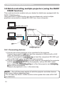
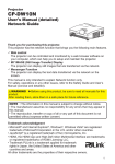
3.8 Batch-controlling multiple projectors (using the DAISY
CHAIN function)
This model and similar models (ask your dealer for details) are equipped with the
DAISY CHAIN function.
Using the DAISY CHAIN function you can simultaneously control multiple
projectors connected to a shared RS-232C bus, from a computer.
RS-232C cable (cross)
[Power ON]
LAN cable
CONTROL IN port
RS-232C cable (cross)
RS-232C cable (cross)
[Power ON]
Computer
LAN port
CONTROL OUT port
3.8.1 Connecting devices
1) Connect one of the projectors to be controlled to the computer.
C
onnect the projector’s LAN port and the computer’s LAN port with a LAN
cable, for Ethernet communication.
C
onnect the projector’s CONTROL IN port and the computer’s RS-232C port
with an RS-232C cable, for RS-232C communication.
2) Connect the CONTROL OUT port of the projector connected to the computer
and the CONTROL IN port of the 2nd projector, with an RS-232C cable.
Then connect the CONTROL OUT port of the 2nd projector and CONTROL
IN port of the 3rd projector.
Connect all projectors in turn, in the same way.
NOTE • Turn off (the power switch of) both the projector and other devices
and unplug, before connecting them.
• Do not apply the DAISY CHAIN function to the system that uses a RS-232C
bus distributor.
50
3. Management with Web browser software
3.8.2 Communication setup
1) Set up the communication condition of the CONTROL IN port of the projector
to be connected to the computer by RS-232C communication, according to
the specifications of the computer’s RS-232C port.
U
sing the SERIAL IN SETTING menu, select the proper baud rate and parity.
(Operating Guide - OPTION menu - SERVICE – COMMUNICATION –
SERIAL IN SETTING/SERIAL OUT SETTING)
2) Set up the same condition of the CONTROL IN port and the CONTROL OUT
port connected each other with the same RS-232C cable.
U
se the SERIAL IN SETTING menu for the CONTROL IN ports, and the
SERIAL OUT SETTING menu for the CONTROL OUT ports, to set up the
baud rate and parity. (Operating Guide - OPTION menu - SERVICE –
COMMUNICATION – SERIAL IN SETTING/SERIAL OUT SETTING)
Communication condition
Item
BAUD RATE
PARITY
Condition
4800bps/9600bps/19200bps/38400bps
NONE/ODD/EVEN
Data length
8 bit (fixed)
Start bit
1 bit (fixed)
Stop bit
1 bit (fixed)
3) Using the COMMUNICATION TYPE menu, select the DAISY CHAIN
for each projector. (Operating Guide - OPTION menu - SERVICE –
COMMUNICATION – COMMUNICATION TYPE)
NOTE • The baud rate and parity of the CONTROL IN port do not need to be
set up when connecting the projector to the computer by Ethernet.
• An incorrect setup may cause a communication malfunction with the external
device.
3.8.3 Communication port
When connecting the projector to the computer by Ethernet, send the data from
the computer to the projector using the TCP # 9718 port.
51
3. Management with Web browser software
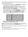
3.8.4 COMMUNICATION GROUP / COMMUNICATION ID
When projectors are controlled in a DAISY CHAIN, set the COMMUNICATION
GROUP and COMMUNICATION ID for each projector separately in order to
control a projector individually or some of the projectors simultaneously.
Use the COMMUNICATION GROUP menu and COMMUNICATION ID
menu to set up them. (Operating Guide - OPTION menu - SERVICE –
COMMUNICATION – COMMUNICATION GROUP / COMMUNICATION ID)
NOTE • The COMMUNICATION GROUP is set to A, and the
COMMUNICATION ID is set to the 1, as the default settings.
• To control some projectors individually, do not set up the same
COMMUNICATION ID to these projectors.
Alternatively, setting up the same COMMUNICATION ID to two or more
projectors intentionally realizes simultaneous control for these projectors, like
the coincident control with the COMMUNICATON GROUP.
3.8.5 Command for Daisy Chain control
For the command control of the DAISY CHAIN function, see the Technical
Operating Guide. (Operating Guide - Technical – Daisy Chain
Communication)
52