1
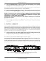
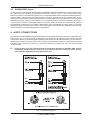
Version 1.0 March 2001 ® SUPER-X PRO www.behringer.com ENGLISH CX2310 Users Manual SUPER-X PRO CX2310 SAFETY INSTRUCTIONS CAUTION: To reduce the risk of electric shock, do not remove the cover (or back). No user serviceable parts inside; refer servicing to qualified personnel. WARNING: To reduce the risk of fire or electric shock, do not expose this appliance to rain or moisture. This symbol, wherever it appears, alerts you to the presence of uninsulated dangerous voltage inside the enclosurevoltage that may be sufficient to constitute a risk of shock. This symbol, wherever it appears, alerts you to important operating and maintenance instructions in the accompanying literature. Read the manual. DETAILED SAFETY INSTRUCTIONS: All the safety and operation instructions should be read before the appliance is operated. Retain Instructions: The safety and operating instructions should be retained for future reference. Heed Warnings: All warnings on the appliance and in the operating instructions should be adhered to. Follow instructions: All operation and user instructions should be followed. Water and Moisture: The appliance should not be used near water (e.g. near a bathtub, washbowl, kitchen sink, laundry tub, in a wet basement, or near a swimming pool etc.). Ventilation: The appliance should be situated so that its location or position does not interfere with its proper ventilation. For example, the appliance should not be situated on a bed, sofa, rug, or similar surface that may block the ventilation openings, or placed in a built-in installation, such as a bookcase or cabinet that may impede the flow of air through the ventilation openings. Heat: The appliance should be situated away from heat sources such as radiators, heat registers, stoves, or other appliances (including amplifiers) that produce heat. Power Source: The appliance should be connected to a power supply only of the type described in the operating instructions or as marked on the appliance. Grounding or Polarization: Precautions should be taken so that the grounding or polarization means of an appliance is not defeated. Power-Cord Protection: Power supply cords should be routed so that they are not likely to be walked on or pinched by items placed upon or against them, paying particular attention to cords and plugs, convenience receptacles and the point where they exit from the appliance. Cleaning: The appliance should be cleaned only as recommended by the manufacturer. Non-use Periods: The power cord of the appliance should be unplugged from the outlet when left unused for a long period of time. Debris and Liquid Entry: Care should be taken that debris and/or liquids do not enter the enclosure through openings. Damage Requiring Service: The appliance should be serviced by qualified service personnel when: - The power supply cord or the plug has been damaged; or - Debris or liquid has entered the appliance; or - The appliance has been exposed to rain; or - The appliance does not appear to operate normally or exhibits a marked change in performance; or - The appliance has been dropped, or the enclosure damaged. Servicing: The user should not attempt to service the appliance beyond that which is described in the operating instructions. All other servicing should be referred to qualified service personnel. 2 SUPER-X PRO CX2310 FOREWORD Dear Customer, Welcome to the team of SUPER-X PRO users and many thanks for the confidence that you have shown in us by purchasing the CX2310. It is one of my most pleasant tasks to write this letter to you, because after many months of hard work our engineers have achieved a very ambitious goal: to present a top-quality piece of equipment which thanks to its flexibility can be used in both live and studio surroundings. The task of developing our new SUPER-X PRO has meant a great deal of responsibility. As we continued to develop it further, you the discerning end-user and musicianwere always at the forefront of our thoughts. Meeting this responsibility also involved us in considerable effort and late-night working, but it was fun, too. This type of development always brings together a large number of people, and it is a great feeling when all those involved can be proud of the results of their work. Our philosophy is that you should also share in this satisfaction. You are the most important member of our team. With your highly competent encouragement and suggestions for new products, you have greatly contributed to shaping our company and to making it successful. In return we guarantee you an uncompromising level of quality (manufactured under ISO9000 certified management system), excellent technical and audio characteristics and an extremely favorable price. All this makes it possible for you to develop your creativity to the fullest, without being hampered by budget constraints. We are often asked how we manage to manufacture equipment of this quality at such unbelievably low prices. The answer is very simple: You make it possible! Many satisfied customers means large sales volumes. Large sales volumes means we can get better purchase prices for components etc. Isnt it only fair for us to pass this benefit back to you? After all, we know that your success is our success, too! I would like to thank everyone who has helped make the SUPER-X PRO possible. All have made their own personal contribution, beginning with the developers, through the many employees of our company and up to you, the user of BEHRINGER products. My friends, its been worth the trouble! Thank you very much, Uli Behringer 3 SUPER-X PRO CX2310 SUPER-X PRO ® High-precision stereo 2-way/mono 3-way crossover with subwoofer output CX2310 s Professional, high-precision stereo 2-way/mono 3-way crossover with separate subwoofer output s World-class performance 24 dB per octave Linkwitz-Riley filters s Absolutely flat summed amplitude response, zero phase difference s Separate subwoofer section with independent frequency control s Individual output level controls for all bands s Individual output mutes for easy band adjustment s Individual phase reverse switches for instant phase correction s Switchable 25 Hz subsonic filter on each input for low-frequency driver protection s Servo-balanced, gold-plated XLR connectors for all inputs and outputs s Ultra-high precision ALPS potentiometers for ultimate accuracy and repeatability s Ultra low-noise audio operational 4580 amplifiers for outstanding sound performance s Illuminated switches for secure operation in dark stage environments s High-quality components and exceptionally rugged construction for long life and reliability s Shielded toroidal mains transformer for minimal noise interference s Manufactured under ISO9000 certified management system 4 SUPER-X PRO CX2310 TABLE OF CONTENTS 1. INTRODUCTION..................................................................................................................... 5 1.1 Before you begin ............................................................................................................................. 5 2. CONTROL ELEMENTS ......................................................................................................... 6 2.1 Stereo 2-way operation with separate subwoofer signal ................................................................... 6 2.2 Mono 3-way operation with separate subwoofer signal .................................................................... 8 3. APPLICATIONS ....................................................................................................................... 9 3.1 3.2 3.3 3.4 3.5 Tools ............................................................................................................................................... 9 Setting the input and output levels ................................................................................................ 10 Correcting problems ...................................................................................................................... 10 Setting the crossover frequencies .................................................................................................. 10 SUBWOOFER Output ................................................................................................................... 11 4. AUDIO CONNECTIONS .........................................................................................................11 5. SPECIFICATIONS ................................................................................................................. 12 6. WARRANTY ........................................................................................................................... 13 1. INTRODUCTION Thank you for the confidence which you have expressed in us by purchasing the SUPER-X PRO CX2310. The BEHRINGER SUPER-X PRO is a high-value, active frequency crossover, extremely well suited for both live and studio applications. If you want to operate a loudspeaker system, which consists of several loudspeakers covering different frequency bands, then you naturally have to work with suitably differentiated input signals for each loudspeaker. To do this you need a frequency crossover which can split the input signal into several frequency bands. A difference should be noted between passive crossovers which are wired between amplifier and speaker, and active systems which are placed before the amplifiers in the signal chain. Multi-way speaker systems can be found almost everywhere todayand not only in stereo systems, but in cinemas, discotheques and concert halls. As customers have become more demanding they can even be found now in such simple products as TV sets. Why? With the same sound pressure, low-frequency sound waves have a much greater amplitude (oscillation range) than high-frequency waves. When a single loudspeaker tries to produce bass and treble frequencies at the same time, a so-called intermodulation distortion will occur. This means that, when the speaker diaphragm is displaced by low frequencies, the treble frequencies seem to be raised in loudness, or lowered when the diaphragm reverses its direction. We cannot therefore expect a single loudspeaker to reproduce signals, spanning the whole audible frequency spectrum at the same level of quality. If, using a frequency crossover, a loudspeaker only has to reproduce a limited part of the frequency spectrum and it will do so at a greatly increased level of qualitythus producing a more regular frequency response and dispersion pattern. + This manual first describes the terminology used, so that you can fully understand the SUPER-X PRO and its functions. Please read the manual carefully and keep it for future reference. 1.1 Before you begin The BEHRINGER SUPER-X PRO CX2310 was carefully packed in the factory, in order to ensure safe transport. Nevertheless, should the box show signs of damage please check the equipment itself immediately for any signs of external damage. 1. INTRODUCTION 5 + SUPER-X PRO CX2310 If the unit is damaged, please do not return it to us, but notify your dealer and the shipping company immediately, otherwise claims for damage or replacement may not be granted. Shipping claims must be made by the consignee. Be sure that there is enough space around the unit for cooling and please do not place the SUPER-X PRO on high-temperature devices such as power amplifiers, etc. to avoid overheating. + Before connecting the SUPER-X PRO to the mains, please carefully check that your equipment is set to the correct supply voltage! The fuse holder on the female mains connector has 3 triangular markings. Two of these triangles are opposite each other. The CX2310 is set to the operating voltage shown next to these markings. It can be set to another voltage by turning the fuse holder through 180°. CAUTION: this does not apply to export models, which were designed e.g. only for a mains voltage of 115 V! Connection to the mains is made by means of a mains cable with an IEC receptacle which complies with the appropriate safety regulations. + Please note that all units must be grounded properly. For your own safety, you should never remove any ground connectors from electrical devices or power cords or render them inoperative. 2. CONTROL ELEMENTS Since the SUPER-X PRO offers a variety of features, we have provided the active controls with suitable lightemitting diodes. These displays help you to keep track of what is happening even in dark stage environments. Additionally, all the switches on the front panel are illuminated and can thus show which functions are presently active. There are two labels in the form of strips, located above the controls. The text of the upper label indicates mono 3-way, and the lower label indicates stereo 2-way mode. The LEDs set below these labels show which controls are active in the respective mode of operation. + On the rear panel, labels above/below the connectors refer to the various crossover modes available. Please make sure that the MODE switch and corresponding connectors are configured properly; otherwise, you could damage your speakers. 2.1 Stereo 2-way operation with separate subwoofer signal First, activate the 2-way mode using the MODE switch on the rear panel (switch depressed). The STEREO LED on the front panel above the LOW CUT switch in the second channel lights up. The LEDs above the active control on the front panel then light up. They show you which controls are active for the mode of operation, which you have selected. The functions of these controls can be seen from the second strip label. In stereo operation the functions of both channels are identical, so that the numbers on the overview are shown for only one channel. Fig. 2.1: Active control elements on the front panel of the SUPER-X PRO in stereo 2-way operation with separate subwoofer signal 6 2. CONTROL ELEMENTS SUPER-X PRO CX2310 1 INPUT control. This control adjusts the input gain over the range from -12 to +12 dB. 2 LOW CUT switch. This switch activates the 25 Hz high-pass filter. It has a side gradient of 12 dB/octave and is used to protect your bass loudspeaker. 3 LOW/HIGH XOVER FREQ. control. This control governs the crossover frequency between the low and high bands. 4 LOW OUTPUT control. Controls the output level of the low band over the range from -6 to +6 dB. 5 LOW PHASE INVERT switch. This switch reverses the polarity of the low output. 6 LOW MUTE switch. This is used to mute the low band. 7 HIGH OUTPUT control. This controls the output level of the high band over the range from -6 to +6 dB. 8 HIGH PHASE INVERT switch. This switch reverses the polarity of the high output. 9 HIGH MUTE switch. This is used to mute the high band. 10 XOVER FREQ. control. This control governs the crossover frequency between the low signal and the subwoofer signal (10 to 235 Hz). 11 GAIN control. This is used to set the subwoofer output volume at the SUBW. OUT output. 12 PHASE INVERT switch. This switch reverses the polarity of the subwoofer output signal. 13 MUTE switch. This mutes the subwoofer output signal. Fig. 2.2: Active control elements and connections on the rear panel of the SUPER-X PRO in stereo 2-way operation with separate subwoofer signal 1 HIGH OUTPUT connectors. These are the balanced XLR connectors for the high band output signal. 2 LOW OUTPUT connectors. These are the balanced XLR connectors for the low band output signal. 3 XOVER FREQ. switch. These switches are used to switch between the control ranges on the front panel LOW/HIGH XOVER FREQ. control. The range is either 44 to 930 Hz or 440 Hz to 9.3 kHz. 4 INPUT connectors. These are the balanced XLR connectors for the input signal. 5 MODE switch. In stereo 2-way operation the switch must be depressed. Please refer to the text on the rear panel of the equipment. + Never activate the MODE and XOVER FREQ. switches without having first switched off the equipment. Switching between these while the equipment is in use produces heavy interference noise which could damage the loudspeakers or the system. 6 SUBW. OUT connector. This is the balanced XLR output for the mono subwoofer signal. This signal is constant in mono and stereo mode and provides an additional means of providing 2- and 3-way operation (see chapter 3.5). 7 IEC-RECEPTACLE. This is the mains connection of the SUPER-X PRO. A suitable mains cable is included with the equipment. 8 FUSE HOLDER /VOLTAGE SELECTOR. Before connecting the equipment to the mains supply, please check that the voltage display conforms with your mains voltage supply. When replacing the fuse, make sure you use another one of the same type. With many units the fuse holder can be set in one of two positions, in order to switch between 230 V and 115 V. Please note: if you wish to operate a unit outside Europe, then a stronger fuse must be used. 9 SERIAL NUMBER. Please take the time to complete and return the warranty card within 14 days of the date of purchase, otherwise you will lose the right to the extended warranty. Or just use our onlineregistration (www.behringer.com). 2. CONTROL ELEMENTS 7 SUPER-X PRO CX2310 2.2 Mono 3-way operation with separate subwoofer signal First activate mono 3-way mode using the MODE switch on the rear panel (switch released). The MONO LED on the front panel above the LOW CUT switch lights up. Then the LEDs above the active control on the front panel light up. They show which controls are active for the mode of operation, which you have selected. The text on the first label shows the functions of these controls. Fig. 2.3: Active control elements on the front panel of the SUPER-X PRO in mono 3-way operation with separate subwoofer signal 1 INPUT control. This control adjusts the input gain from -12 to +12 dB. 2 LOW CUT switch. This switch activates the 25 Hz high pass filter. 3 LOW/MID XOVER FREQ. control. This control governs the crossover frequency between the low and middle bands. 4 LOW OUTPUT control. This controls the output level of the low band over the range -6 to +6 dB. 5 LOW PHASE INVERT switch. This switch is used to reverse the polarity of the low output. 6 LOW MUTE switch. This is used to mute the low band. 7 MID/HIGH XOVER FREQ. control. This control governs the crossover frequency between the mid and high bands. 8 MID OUTPUT control. This is used to control the output level of the mid band over the range -6 to +6 dB. 9 MID PHASE INVERT switch. This reverses the polarity of the mid output. 10 MID MUTE switch. This is used to mute the mid band. 11 HIGH OUTPUT control. This controls the output level of the high band over the range from -6 to +6 dB. 12 HIGH PHASE INVERT switch. This reverses the polarity of the high output. 13 HIGH MUTE switch. This is used to mute the high band. 14 XOVER FREQ. control. This control governs the crossover frequency between the low signal and the subwoofer signal. 15 GAIN control. This sets the subwoofer output volume level at the SUBW.OUT output. 16 PHASE INVERT switch. This switch is used to reverse the polarity of the subwoofer output signal. 17 MUTE switch. This is used to mute the subwoofer output signal. 8 2. CONTROL ELEMENTS SUPER-X PRO CX2310 Fig. 2.4: Active control elements and connections on the rear panel of the SUPER-X PRO in mono 3-way operation with separate subwoofer signal 1 HIGH OUTPUT connector. This is the balanced XLR connector for the high output signal. 2 MID OUTPUT connector. This is the balanced XLR connector for the mid output signal. 3 LOW OUTPUT connector. This is the balanced XLR connector for the low output signal. 4 XOVER FREQ. switch. This is used to switch between the control ranges of the front panel MID/HIGH XOVER FREQ. control. The range is either 44 to 930 Hz or 440 Hz to 9.3 kHz. 5 XOVER FREQ. switch. This is used to switch between the control ranges of the front panel LOW/MID XOVER FREQ. control. The range is either 44 to 930 Hz or 440 Hz to 9.3 kHz. 6 INPUT connector. This is the balanced XLR connector for the input signal. 7 MODE switch. This must be de-activated when in mono 3-way operation. + 8 Never activate the MODE and XOVER FREQ. switches without having first switched off the equipment. Switching between these whilst the equipment is in use produces heavy interference noise which could damage the loudspeakers or the system. SUBW. OUT connector. This is the output for the mono subwoofer signal. This signal remains constant in mono and stereo mode and offers an additional way of providing 2-way and 3-way operation (see chapter 3.5). 3. APPLICATIONS You will need some tools to help set up the SUPER-X PRO to its optimal configuration. To set up the crossover frequency you need to know which frequency range a loudspeaker stack covers, over which range the sound energy is linearly transmitted, and where reductions or increases in the frequency response occur. In addition, every room has different size and quality characteristics. These strongly influence the sound response, since resonances and reflections in the different frequency ranges can also lead to reductions or increases in the sound picture. You will need suitable equipment in order to be able to recognize and compensate for these features. 3.1 Tools You will need a high-grade microphone for making measurements. This should have a frequency response that should be as linear as possible (e.g. the BEHRINGER measurement microphone ECM8000) and at least linear over the range from 90 Hz and 15 kHz. Place the microphone about 5 m. in front of the speaker system and between the diaphragms of the two frequency bands you wish to measure. When using a measuring microphone to set the levels for the individual frequency bands and the crossover frequencies, you should only operate one loudspeaker stack. For optimal settings you will usually need to reposition the microphone between two successive measurements. When used in combination with a measuring microphone and a generator producing pink noise via an input into the P.A. mixing console, an analyzer will show the sound energy distribution over the individual frequency bands (usually in 1/3 of an octave). The BEHRINGER ULTRA-CURVE PRO DSP8024 equalizer/analyzer is the ideal tool for this application. When listening to the overall sound of your system, you should walk around in the audience area and try to detect resonance frequencies or cancellations. The sound should be optimized for the position where most of the audience will be gathered, without however neglecting other areas. This often means that the system must be operated in mono. Whenever you use technical aids such as analyzers, measuring microphones, etc., you should check the desired results with your own ears. 3. APPLICATIONS 9 + SUPER-X PRO CX2310 BEHRINGER accepts no responsibility for any damage or destruction of loudspeakers arising from improper or incorrect use of the SUPER-X PRO and in particular from actions which are in contravention with the clearly stated procedures given in this manual. 3.2 Setting the input and output levels Both inputs offer a gain or loss of up to 12 dB. Normally, the output level on the mixing console and the input sensitivity of the amplifiers are identical, i.e. 0 dB at the mixing console corresponds with 0 dB at the amplifiers. This means that there is full control over the amplifiers. In this case the SUPER-X PRO should have no effect on the system level and all input and output level settings should be set at 0 dB. Where e.g. a home recording or disco console is being used with an operating level of -10 dBV but the amplifiers need +4 dBu for complete control, then an additional gain of 12 dB must be provided between them. In this case the INPUT control of the SUPER-X PRO should be set to the maximum. The output levels of the single bands can be raised/lowered by as much as 6 dB. To achieve a linear frequency response in the system, all output levels should be adjusted with the help of an analyzer. To check the crossover frequencies and levels, mute all outputs except for one, and play back pink noise over the system at an appropriate volume level. When you now switch on the adjacent band, the level measured around the crossover frequency should go up by 3 dB. Repeat this process for all crossover frequencies. 3.3 Correcting problems Check the entire frequency response of the system. Rooms have quite an impact on the frequency response of speaker systems, due to resonance and various reflections, so you cannot expect to achieve a linear frequency response right from the start. To achieve this, you need an equalizer such as the ULTRA-CURVE PRO DSP8024 or the ULTRA-GRAPH GEQ3102. Look for drop-outs around the crossover frequencies! If the frequency response is very irregular, then it can make sense to grade adjust it using the frequency crossover, before using an equalizer (EQ). The errors in the crossover frequency must then be as far as possible corrected using the EQ. If the loudspeaker diaphragms in a multi-way system are not exactly aligned along a vertical axis, the varying distances between the sound source and the listener result in phase errors and cancellations (also known as the comb filter effect). Particularly in the higher frequencies it is important, due to the shorter wavelengths, to position the diaphragms above each other and not next to each other. The various types of construction used in individual systems (horns, bass reflex cabinets etc.) still give rise to run time differences, even where the front sides of all systems are aligned vertically above each other. In this case a run time correction must be made by electronic means. This can be done by using a delay function. Run time differences can be compensated by delaying the frequency bands over a range of milliseconds. This helps avoid loss of sound quality, particularly in the high tone ranges. + Runtime correction is not the same as phase correction. If a speaker system has the same run times then it also has the same phases (unless the polarity of a cable has been reversed). However the opposite is not necessarily true. 3.4 Setting the crossover frequencies The frequency range from which the crossover frequencies can be selected, can be one of two rangesfrom 44 to 930 Hz and from 440 Hz to 9.3 kHz. To set the crossover frequencies, please first read the manufacturers specifications for the individual loudspeaker components. To use the capacity of your system at its best you should set up the crossover frequencies in accordance with the frequency diagrams on the individual loudspeaker boxes. Further, the crossovers should not lie on peaks or drop-outs. Look for a range with the flattest possible curve. If folded bass horns are being used, then the length of the horn path must also be taken into account, since the run time displacements arising from differing long paths can also have a negative effect on the frequency development (see chapter 3.3). + 10 Never operate loudspeakers or horn drivers below the limiting frequency specified by the manufacturer! 3. APPLICATIONS SUPER-X PRO CX2310 3.5 SUBWOOFER Output To achieve a very loud and deep bass playback the SUPER-X PRO has an additional mono subwoofer output for 2-way and 3-way operation. In this sense the CX2310 is a stereo 2-way + mono 1-way or mono 4-way frequency crossover. The subwoofer signal is mono, since people cannot sense the location of lower frequencies. Another reason is that combining all bass signals into a single signal produces an excellent effect. This is because two bass speaker boxes combined together produce 3 dB more sound pressure than if they were separated from each other by a small distance. The increased pressure is due to the speakers producing a single wave front. With four loudspeaker boxes the increase is 6 dB. The reason here is the spherical shape of the expanding low-frequency sound waves. Bass boxes which are separate from each other can mutually disrupt each other where their sound waves meet (what happens here can be easily imagined if you throw two stones into waterfirst separately and then stuck together). 4. AUDIO CONNECTIONS As a standard, the BEHRINGER SUPER-X PRO CX2310 is equipped with electronically servo-balanced inputs and outputs. The circuit design features automatic hum suppression for balanced signals and so ensures trouble-free operation, even at the highest operating levels. Externally induced mains hum, etc. can therefore be effectively suppressed. The automatic servo-function recognizes the presence of unbalanced connectors and adjusts the nominal level internally to avoid level differences between the input and output signals (6-dB correction). + Please ensure that only qualified persons install and operate the SUPER-X PRO. During installation and operation the user must have sufficient electrical contact to earth. Electrostatic charges might affect the operation of the unit. Fig. 4.1: Different plug types 4. AUDIO CONNECTIONS 11 SUPER-X PRO CX2310 5. SPECIFICATIONS INPUTS Connectors Type Impedance Max. Input level CMRR XLR Electronically servo-balanced, HF filtered balanced >50 kOhm, unbalanced >25 kOhm +22 dBu typical, balanced or unbalanced >40 dB, typical >55 dB at 1 kHz OUTPUTS Connectors Type Impedance Max. Output level XLR Electronically servo-balanced, HF filtered balanced 60 Ohm, unbalanced 30 Ohm +20 dBm balanced/unbalanced PERFORMANCE Bandwidth Frequency response Signal to noise Low output Mid output High output Interchannel crosstalk CROSSOVER Filter-Type Mono Mode Frequencies Low/High Low/Mid Mid/High Stereo Mode Frequencies Low/High POWER SUPPLY Mains voltage 20 Hz to 20 kHz, +0/-0.5 dB <5 Hz to >60 kHz, +0/-3 dB Ref.: +4 dBu, 20 Hz to 20 kHz, unweighted Stereo-Mode: Mono-Mode: >93 dB >93 dB >95 dB >91 dB >91 dB High to Low: <93 dB High to Mid: <94 dB Mid to Low: <95 dB Linkwitz-Riley, 24 dB/octave, state-variable x1 x10 44 to 930 Hz 440 Hz to 9.3 kHz 44 to 930 Hz 440 Hz to 9.3 kHz 440 Hz to 9.3 kHz x1 x10 44 to 930 Hz 440 Hz to 9.3 kHz Mains connection USA/Canada U.K./Australia Europe General Export Model <17 W UL Europe JP Standard IEC receptacle PHYSICAL/WEIGHT Dimensions Weight approx. 1 ¾" (44.5 mm) * 19" (482.6 mm) * 8 ½" (217 mm) approx. 3 kg Power consumption Fuse 120 V ~, 60 Hz 240 V ~, 50 Hz 230 V ~, 50 Hz 100 - 120 V ~, 200 - 240 V ~, 50 - 60 Hz 100 -120 V ~: T 630 mA H 200 - 240 V ~: T 315 mA H 90 - 110 V ~: T 630 mA H BEHRINGER is constantly striving to maintain the highest professional standards. As a result of these efforts, modifications may be made from time to time to existing products without prior notice. Specifications and appearance may differ from those listed or illustrated. 12 5. SPECIFICATIONS SUPER-X PRO CX2310 6. WARRANTY § 1 WARRANTY CARD/ONLINE REGISTRATION To be protected by the extended warranty, the buyer must complete and return the enclosed warranty card within 14 days of the date of purchase to BEHRINGER Spezielle Studiotechnik GmbH, in accordance with the conditions stipulated in § 3. Failure to return the card in due time (date as per postmark) will void any extended warranty claims. Based on the conditions herein, the buyer may also choose to use the online registration option via the Internet (www.behringer.com or www.behringer.de). § 2 WARRANTY 1. BEHRINGER (BEHRINGER Spezielle Studiotechnik GmbH including all BEHRINGER subsidiaries listed on the enclosed page, except BEHRINGER Japan) warrants the mechanical and electronic components of this product to be free of defects in material and workmanship for a period of one (1) year from the original date of purchase, in accordance with the warranty regulations described below. If the product shows any defects within the specified warranty period that are not due to normal wear and tear and/or improper handling by the user, BEHRINGER shall, at its sole discretion, either repair or replace the product. 2. If the warranty claim proves to be justified, the product will be returned to the user freight prepaid. 3. Warranty claims other than those indicated above are expressly excluded. § 3 RETURN AUTHORIZATION NUMBER 1. To obtain warranty service, the buyer (or his authorized dealer) must call BEHRINGER (see enclosed list) during normal business hours BEFORE returning the product. All inquiries must be accompanied by a description of the problem. BEHRINGER will then issue a return authorization number. 2. Subsequently, the product must be returned in its original shipping carton, together with the return authorization number to the address indicated by BEHRINGER. 3. Shipments without freight prepaid will not be accepted. § 4 WARRANTY REGULATIONS 1. Warranty services will be furnished only if the product is accompanied by a copy of the original retail dealers invoice. Any product deemed eligible for repair or replacement by BEHRINGER under the terms of this warranty will be repaired or replaced within 30 days of receipt of the product at BEHRINGER. 2. If the product needs to be modified or adapted in order to comply with applicable technical or safety standards on a national or local level, in any country which is not the country for which the product was originally developed and manufactured, this modification/adaptation shall not be considered a defect in materials or workmanship. The warranty does not cover any such modification/adaptation, irrespective of whether it was carried out properly or not. Under the terms of this warranty, BEHRINGER shall not be held responsible for any cost resulting from such a modification/adaptation. 3. Free inspections and maintenance/repair work are expressly excluded from this warranty, in particular, if caused by improper handling of the product by the user. This also applies to defects caused by normal wear and tear, in particular, of faders, potentiometers, keys/buttons and similar parts. 4. Damages/defects caused by the following conditions are not covered by this warranty: s misuse, neglect or failure to operate the unit in compliance with the instructions given in BEHRINGER user or service manuals. s connection or operation of the unit in any way that does not comply with the technical or safety regulations applicable in the country where the product is used. s damages/defects caused by force majeure or any other condition that is beyond the control of BEHRINGER. 5. Any repair or opening of the unit carried out by unauthorized personnel (user included) will void the warranty. 6. If an inspection of the product by BEHRINGER shows that the defect in question is not covered by the warranty, the inspection costs are payable by the customer. 7. Products which do not meet the terms of this warranty will be repaired exclusively at the buyers expense. BEHRINGER will inform the buyer of any such circumstance. If the buyer fails to submit a written repair order within 6 weeks after notification, BEHRINGER will return the unit C.O.D. with a separate invoice for freight and packing. Such costs will also be invoiced separately when the buyer has sent in a written repair order. § 5 WARRANTY TRANSFERABILITY This warranty is extended exclusively to the original buyer (customer of retail dealer) and is not transferable to anyone who may subsequently purchase this product. No other person (retail dealer, etc.) shall be entitled to give any warranty promise on behalf of BEHRINGER. § 6 CLAIM FOR DAMAGES Failure of BEHRINGER to provide proper warranty service shall not entitle the buyer to claim (consequential) damages. In no event shall the liability of BEHRINGER exceed the invoiced value of the product. § 7 OTHER WARRANTY RIGHTS AND NATIONAL LAW 1. This warranty does not exclude or limit the buyers statutory rights provided by national law, in particular, any such rights against the seller that arise from a legally effective purchase contract. 2. The warranty regulations mentioned herein are applicable unless they constitute an infringement of national warranty law. The information contained in this manual is subject to change without notice. No part of this manual may be reproduced or transmitted in any form or by any means, electronic or mechanical, including photocopying and recording of any kind, for any purpose, without the express written permission of BEHRINGER Spezielle Studiotechnik GmbH. BEHRINGER, SUPER-X, ULTRA-CURVE and ULTRA-GRAPH are registered trademarks. ALL RIGHTS RESERVED. © 2001 BEHRINGER Spezielle Studiotechnik GmbH. BEHRINGER Spezielle Studiotechnik GmbH, Hanns-Martin-Schleyer-Str. 36-38, 47877 Willich-Münchheide II, Germany Tel. +49 (0) 21 54 / 92 06-0, Fax +49 (0) 21 54 / 92 06-30 6. WARRANTY 13