1
ADL2Net v0.8
Reference Manual
Marcela Rivera
April 18, 2006
1
1.1
Introduction
What is ADL2N?
ADL2N is a multiplatform tool written in Java that provides an easy generation of behaviour models for
the Fractal Component Model. Starting from a component specification written in ADL (Architecture
Description Language), this application automatically generates the behaviour model expressed as
an Labelled Transition System (in FC2 format). As input, the user should provide the ADL and
implementations of the interfaces defined within the ADL (needed to extract methods signatures), and
the behaviour of each primitive component (in the current version it is not yet mandatory) in either
FC2 or LOTOS code.
Although the output model is parameterized, there are no model-checking available that can handle them. Fortunately, they can easily instantiated and then used in finite-state model-checking tools.
Once created, the model can be directly used with CADP to check several properties such as deadlock freedom, liveness, fairness or reachability. In future versions the user may check non-functional
properties, thus reconfiguration problems may be found before actually launching the application.
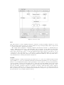
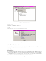
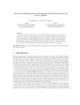
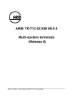
This application fits within the Vercors framework currently developed at the OASIS Project from
INRIA Sophia-Antipolis. We are building a tool platform (see figure 1) for the analysis and verification
of safety and security properties of distributed applications. The central component of the platform is
a method for generating finite models for distributed applications, from static analysis of source code.
We base this generation procedure on the strong semantic features provided by the ProActive library,
and we generate compositional models using synchronised labelled transition systems. Various tools
for static analysis, model checking, and equivalence checking can then operate on these models. One
long term goal of this work is to integrate the various techniques and tools involved in this software
platform, so that the platform can be integrated in a development environment, and used by nonspecialists. At the same time, the platform must be flexible and open enough to serve as a basis for
easy prototyping of new techniques and tools on real Java/ProActive code.
1.2
Basic Concepts
Components
In general words, a component is a self contained entity that interacts with its environment through
well-defined interfaces: provided services and required functionalities (to be provided by other components). Besides these interactions, a component does not reveal its internal structure. For more
information see [1].
Architecture Description Language - ADL
The Fractal Architecture Description Language (ADL) is an open and extensible language to define
component architectures for the Fractal component model, which is itself open and extensible. More
precisely, the Fractal ADL is made of an open and extensible set of ADL modules, were each module
defines an abstract syntax for a given architectural ”aspect” (such as interfaces, bindings, attributes,
or containment relationships). Users are then free to define their own modules for their own aspects.
They can also define their own concrete syntax for the language. For more information see [1].
1
Figure 1: Vercors toolset
FC2
The FC2 format [3, 9] was originally designed to interface several preexisting verification tools [8].
In this way these heterogeneous tools could be further developed independently, while being used in
cooperation with their complementary features.
The format allows description of labelled transition systems and networks of communicating automata. While the format is not ”syntax-friendly” (as it represent objects which are supposedly
obtained by translation or compilation), it is still reasonably natural: automata are tables of states,
states being each in turn a table of outgoing transitions with target indexes; networks are vectors
of references to subcomponents (i.e., to other tables), together with synchronisation vectors (legible
combinations of subcomponent behaviours acting in synchronised fashion). Subcomponents can be
networks themselves, allowing hierarchical descriptions.
LOTOS
LOTOS (Language of Temporal Ordering Specification) is one of the two Formal Description Techniques (FDT) [7, 6] developed within ISO (International Standards Organisation) for the formal specification of open distributed systems, and in particular for those related to the Open Systems Interconnection (OSI) computer network architecture [5]. The basic idea that LOTOS developed from was
that systems can be specified by defining the temporal relation among the interactions that constitute the externally observable behaviour of a system. Contrary to what the name seems to suggest,
this description technique is not related to temporal logic, but is based on process algebraic methods.
More specifically, the component of LOTOS that deals with the description of process behaviours and
interactions has borrowed many ideas from [10, 4].
2
2
Running the application
2.1
Requirements
PC Linux or Windows system Java Platform Standard Edition 5.0 (J2SE)
2.2
Installation
The ADL2N v0.8 is available at: http://www-sop.inria.fr/oasis/Vercors/software2/adl2n-v0.8.zip
Unzip the package adl2n-0.3.zip into the desired directory. A root folder called adl2n will be created
containing the following components:
examples/
(Some examples)
lib/
(Some additional Java libraries needed for ADL2N)
adl2n.jar
(The ADL2N Java archive)
ADL2N.bat (A Windows script for running ADL2N)
ADL2N.sh
(A Linux script for running ADL2N)
2.3
Setting up the examples
1. Prepare the example files: you need the ADL definition of your system and the definition of a
Java interface for each of the component interface. Compile the Java interfaces before running
the ADL2N tool.
For example, at examples/pots directory:
./compile.sh pots
compile.bat pots
(to compile the pots example in Linux)
(to compile the pots example in Windows)
2. Once compiled, they are ready to be used. Run the ADL2N script from the installation directory,
giving as argument the name of the directory containing the example files; for example, from the
root directory run:
./ADL2N.sh pots
ADL2N.bat pots
(for Linux users)
(for Windows users)
The BufferComponent is different, we only provide the ADL and interfaces already compiled
(.class files) within the folder Components/bin. To test it with ADL2N, it must be run as
following:
./ADL2N.sh BufferComponents/bin
ADL2N.bat BufferComponents\bin
(for Linux users)
(for Windows users)
Note 1: if there is a problem with the classloader, please check the path described in the
classpath. It is recommended to leave all sources (.class, .fractal) in the same folder.
Note 2: Linux users can get a ”permission denied” error when running the script. Please check
the permissions of the file, change it (chmod 755 ADL2N.sh), and try again.
2.4
Common usage scenario:
• Select a Fractal source file by choosing FILE/OPEN from the main menu
• In the structure panel on the left, select the root component
• in the Description view, select the parameters you want to observe in the model
• repeat the first two steps for the other components
• generate the fc2 parameterized file(s) using the ”FC2 Param” menu
• in the Instantiation view, specify the domains of the parameters
3
• save the FC2 files using the ”FC2 Param” menu
The model is ready, the program has created pair of files <comp>.fc2 and <comp>Inst.fc2 for
each component involved.
Tips: for preparing and editing ADL files, you can use the Fractal/Proactive GUI, provided by the
ProActive distribution:
• Run as: $PROACTIVE/script/unix/ic2d.sh
• Activate the Components/Start the component GUI button
• Within the GUI, set the storage directory form the file menu before opening an existing or
creating a new ADL (.fractal) file.
3
User Manual
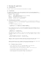
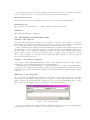
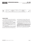
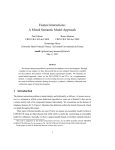
The main window is composed by three sections as seen in figure 2: the menu on top, the hierarchical
tree on the left and tabs in the main frame.
Figure 2: Main window
3.1
The menu toolbar
The available menus in the application are: File, Description, FC2 Param, LOTOS and About.
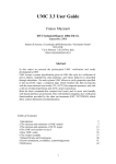
File Menu
Open: choose the fractal file. Note: the directory where the complementary files are located must
be defined in the classpath before launching the application.
Exit:
closes the application.
Description Menu
Asynchronous requests:
Sets the translation output into asynchronous messages.
Asynchronous requests:
Sets the translation output into synchronous method calls.
4
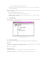
Figure 3: File Menu
Figure 4: Description Menu
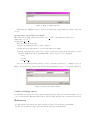
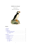
FC2 Param. Menu
Generate FC2 parameterized (pFC2): generates the hierarchical FC2 code associated with the
selected component. The output will be written into the main frame described in 3.3. Note that both
the component and its subcomponents are included, but not further descendants.
Generate hierarchical pFC2 subtree: generates the full hierarchical FC2 code starting from the
selected component from the hierarchical tree frame. The output will be placed in the main frame.
Save FC2 parameterized: saves the generated FC2 parameterized (pFC2) into a user defined
filename (example <filename>.fc2) and the associated instantiation file in the same folder (example
<filename>Inst.fc2).
Save hierarchical pFC2 tree: saves the code to an user defined file generated by ”Generate hierarchical pFC2 subtree” and then writes the instantiation file and the SVL script.
5
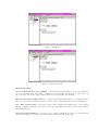
Figure 5: FC2 Param. Menu
LOTOS Menu
This feature is still under construction.
About
General information about the program and its developers.
Figure 6: About Menu
3.2
Hierarchical tree frame
Shows the system structure as a tree. The user may select a component and see its description in the
main frame 2 or generate either FC2 or LOTOS code.
3.3
Tabs
Description tab
Shows the description of the component selected by the hierarchical tree frame. In this section it is
possible to set the multiplicity of the components and the visibility of each method and its arguments.
Within the description, the user may see the component name, the behaviour file (LOTOS filename
if it is a primitive component), its multiplicity and the attached interfaces.
6
In the same window there is a list of currently defined variables. If one is selected, the new variable
will be created as its alias, i.e., both variables will be given the same instantiation.
FC2Parameterized tab
Shows the generated FC2 code with the latest selected option from the FC2Param menu.
Instantiation tab
Shows the FC2 code instantiation, i.e., defined variables and associated values.
LOTOS tab
This feature is still under construction.
3.4
Specification of observable events
Visibility of the methods
For each method shown in the description, it is possible to define if it will be visible or not (in the
FC2 translation). If a method is visible, its synchronisation vector will be labelled with a non-internal
action, whereas if invisible it will be internal (tau). By default all methods are visible.
The communications and synchronisations will still happen as usual for the invisible methods, but
the user will not be able to see them as they are considered internal actions. This allows the various
model-checking tools to minimise the resulting automata and remove many unwanted intermediate
method calls not relative to the property the user may be seeking to prove. Remember to always
choose a proper abstraction to keep the model as simple as possible, otherwise you are very likely to
have the state-explosion problem.
Visibility of the method’s arguments
It is possible to define which arguments will be visible. If the argument is visible, it will be included
in the FC2 code. By default all arguments are hidden (invisible).
When unchecked, the arguments will not be included and should be considered as a simplification
to the model. By combining the visibility strategies of the methods with their arguments, the user
may tackle more realistic models while letting the model-checkers find more human-readable counterexamples.
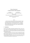
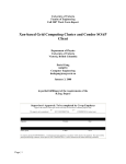
Multiplicity of the components
To set the method’s multiplicity, the multiple checkbox must be selected (if not checked) or click the
’Add’ button. A new window will appear as seen in figure 7, on which the variable name and value
must be specified. A default value will be suggested. To accept the new instantiation click on ’Add’.
The recently created variable can now be seen in the component description.
Figure 7: Add variable window
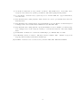
To remove a variable, click on button ’Remove’ which will create a pop up window with the available
variables (figure 8). Choose the variable to remove and click on ’Remove’.
7
Figure 8: Remove variable window
Unchecking the ’Multiple’ checkbox removes all variables specified within the current component
at once.
Specify names and parameters domains
The name pattern must contain only letters or the ’ ’ symbol, and must start with a letter.
Valid name: var, var a
Invalid name: var
There are 4 instantiation types:
• integer: A non-negative discrete value, example 1.
• string: Associate this variable to a previously defined one (alias).
• interval: integer interval, either lower or upper bound may be integers (non-negative) or name
variables. Must start with ’(’ and finish with ’)’ and be separated by ’,’. Example:
– (1,4)
– (2,var)
– (var a,var b)
• set: set of elements specified between ’{’ and ’}’. Items are separated by ’,’. Example: {1,3,5,7}
Note:
To specify global variables, the user should add variables to the root component. (Figure 9)
Figure 9: Add global variable window
Contact and bugs report
For information on the latest releases, updates and papers please visit [2] or send us an email to vercors
< at > sophia.inria.fr. This is the first version of the program, therefore any comments are welcomed.
References
[1] The fractal component model. http://fractal.objectweb.org/specification/index.html.
[2] The vercors platform. http://www-sop.inria.fr/oasis/Vercors/index.html.
8
[3] A. Bouali, A. Ressouche, V. Roy, and R. de Simone. The FC2Tools set. In D. Dill, editor,
Computer Aided Verification (CAV’94), Standford, June 1994. Springer-Verlag, LNCS.
[4] C. A. R. Hoare. Communicating sequential processes. Prentice-Hall, Inc., Upper Saddle River,
NJ, USA, 1985.
[5] ISO: Information Processing Systems. Basic reference model for open systems interconnection.
ISO 7498, 1983.
[6] ISO: Information Processing Systems - Open Systems Interconection. Estelle - a formal description
technique based on an extended state transition model. ISO 9074, 1987.
[7] ISO: Information Processing Systems - Open Systems Interconection. LOTOS - a formal description technique based on the temporal ordering of observational behaviour. ISO 8807, August
1989.
[8] E. Madelaine. Verification tools from the CONCUR project. EATCS Bull., 47, 1992.
[9] E. Madelaine and R. de Simone. The FC2 reference manual, 1993.
ftp-sop.inria.fr/meije/verif/fc2.userman.ps.
available by ftp from
[10] R. Milner. Communication and Concurrency. Prentice Hall, 1989. ISBN 0-13-114984-9.
9