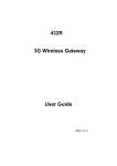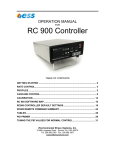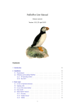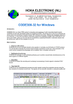
1
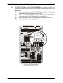
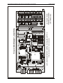
T2160 REMOTE CONTROL LINK Remote Control Signalling Unit Handbook
ISSUE A4-0596
T2160 "REMOTE CONTROL LINK"
USER'S MANUAL
CONTENTS
Page
General
Warranty Statement & Disclaimer
Introduction
Programming Instructions
.....
Hardware
Software
Input Specifications
Analog Inputs & Calibration
Digital Inputs
Output Specifications
Analog Outputs
Digital Outputs
Indicators
Installation
Location of Unit
Mounting the T2160
Interface Specifications
Transmit Signal Output
Constant Tone Output
Receive Signal Input
PTT Output
Channel Busy Input
Fitting Optional PTT Relay
Optional Line Transformer
Electrical Specifications
Troubleshooting
Component Layout
Main Board Schematic
Relay Board Schematic
Sea Air and Land Communications Ltd, Christchurch, New Zealand
.....
.....
.....
.....
.....
.....
.....
.....
.....
.....
.....
.....
.....
.....
.....
.....
.....
.....
.....
.....
.....
.....
.....
.....
.....
.....
.....
.....
2
2
3
4
4
5
5
5
5
7
7
7
7
8
8
8
9
9
9
9
10
10
11
12
13
13
14
15
16
Page 1
T2160 REMOTE CONTROL LINK Remote Control Signalling Unit Handbook
ISSUE A4-0596
TM
GENERAL INFORMATION
WARRANTY STATEMENT
WARRANTY
Our Products are warranted for a period of 24 months from date of
purchase against faulty materials and workmanship. Should any
fault occur the unit should be returned to the Vendor, freight prepaid. Please include a brief description of the fault to assist with
prompt return. any unauthorized alterations or repairs will
invalidate the warranty.
DISCLAIMER
All information provided in this document is carefully prepared and
offered in good faith as a guide in the installation, use and
servicing of our products. Installers must ensure that the final
installation operates satisfactorily within the relevant regulatory
requirements.
We accept no responsibility for incorrect
installation.
We reserve the right to change products,
specifications, and installation data at any time, without notice.
Sea Air and Land Communications Ltd, Christchurch, New Zealand
Page 2
T2160 REMOTE CONTROL LINK Remote Control Signalling Unit Handbook
1.0
ISSUE A4-0596
INTRODUCTION: "REMOTE CONTROL LINK" is a new generation telecontrol
range produced specifically with the small to medium user in mind. The module
incorporates the very latest in random tone signalling technology which allows
the unit to be used on a wide range of communication networks with the absolute
minimum of installation and setup procedures. The versatility and rugged nature
of the signalling formats used will ensure that reliable operation will be
experienced over long periods of operation.
The basis for this product is the single chip random tone technology provided by
the propriety SIGTEC MD09 microprocessor which is placed under the control
of a CPU (Central Processor Unit 87C552).
T2110 PCB Assembly
(Telemetry Board)
Programming Socket
(PL1)
T2110 PCB Assembly
Insertion/Removal
Pillar (One each side)
4
4
4
TB8
TB9
4
1 4
1
TB7
1 4
1 4
TB4
TB5
TB3
Mother board:
Fixed to chassis
1 4
TB10
1 4
TB1
1
1 4
TB1
1 4
TB6
1
1
TB2
Sea Air and Land Communications Ltd, Christchurch, New Zealand
TB6, TB11 and Relays
are optional and are
not always fitted.
Page 3
T2160 REMOTE CONTROL LINK Remote Control Signalling Unit Handbook
ISSUE A4-0596
The "REMOTE CONTROL LINK" signalling module can be utilized to continually
monitor 2 analog and 8 digital signals and relay the status or condition of these
inputs back to a base station either over line or radio circuits. "REMOTE
CONTROL LINK" also has the ability to perform remotely a number of control
functions (2 analog and 8 digital) when instructed by companion controlling unit.
The basic configuration for "REMOTE CONTROL LINK" is commonly referred
to, as the MASTER/SLAVE format. This is where the "MASTER" controls and
reads back from the "SLAVE" it's current input and output conditions.
A wide range of other configurations for "REMOTE CONTROL LINK" are also
possible including control of a number of "SLAVES" using a universal or purpose
built Personal Computer base controller.
If further information is required on any aspect of the "REMOTE CONTROL
LINK" range please contact your nearest SIGTEC/SIGTONE Office.
2.0
PROGRAMMING INSTRUCTIONS: All programming is carried out by the IBM
PC programming kit which is provided as an accessory item. This kit consists
of the following items:
(1)
Sigtec P9932 universal hardware programming kit.
(2)
Sigtec T2160/WE01 IBMTM acompatible Product Support diskette. This
is available in either 5.25 or 3.5 inch formats.
The programming facility of "REMOTE CONTROL LINK" allows the unit to be
tailored to a number of options. All programmed paramaters reside in nonvolatile memory (EEPROM) i.e. the programmed information will not be lost in
the case of power failure.
2.2
Programming Procedure: Programming "REMOTE CONTROL LINK"
to your specific requirements is achieved by removing the top cover from
the T2160 and inserting the P9932 programming wand (S1515/01 option)
into PL1 socket (see figure 1).
2.3
Hardware: Connect the P9932 to the printer port of the IBM PC to be
used as the programming computer as per the instructions provided with
the programming kit.
Select the S1515 programming probe as outlined in Section 4 of the
P9932 operating instructions.
This is plugged into the PCB header socket (PL1) provided on the
T2110/01 PCB assembly (refer to figure 1).
NOTE: The Header socket has a polarizing pin. It is important that the
programming probe is inserted into the socket in the correct way taking
into account the polarizing pin which is matched directly to the missing
probe pin.
Sea Air and Land Communications Ltd, Christchurch, New Zealand
Page 4
T2160 REMOTE CONTROL LINK Remote Control Signalling Unit Handbook
ISSUE A4-0596
It is now possible to apply the power to "REMOTE CONTROL LINK" and
you are now ready for programming.
2.3
Software:
Using the software provided (T2160/WE01), boot the
program in the normal way using the batch file provided. If your computer
is fitted with a hard disk it suggested that the programming software be
installed onto this for ease of use.
The software provides all the information necessary to effect speedy and
efficient programming. Also included within the programming software is
a full Handbook and other general information.
3.0
INPUT SPECIFICATIONS:
3.1
Analog Inputs: "REMOTE CONTROL LINK" as supplied in its standard
format, has two analog inputs. Each of these inputs are configurable to
1.5 to 30 volts, or 0 to 20mA.
3.2
Re-Calibration of Analog Inputs: An example of voltage calibration of
analog 1, and current calibration of analog 2 is described below and
illustrated in figure 2.
3.3.1 Analog 1 - 0 to 5 Volt Calibration: Apply the maximum required
source voltage to terminal block ANALOG 1 IN (TB3-3). Connect
a voltmeter to ANALOG 1 OUT (TB8-3). Apply an earth to
EXTERNAL INPUT 1 (TB5-4) which forces ANALOG 1 OUT to
read ANALOG 1 IN and adjust VR1 for an output of 5 volts.
3.3.2 Analog 2 - 0 to 20mA Calibration: Connect a 100O resistor
between ANALOG 2 IN (TB3-4) and earth (if the T2160 is release
1 -subsequent releases have provision for fitting this resistor on
the main PCB). Connect a current source to ANALOG 2 IN (TB34) and set to 20mA. Connect a voltmeter to ANALOG 2 OUT (TB84). Apply an earth to EXTERNAL INPUT 1 (TB5-4) which forces
ANALOG 2 OUT to read ANALOG 2 IN and adjust VR2 for an
output of 5 volts.
3.3
Digital Inputs: "REMOTE CONTROL LINK" comes with 8 digital inputs
as standard. Six of these inputs are configured to TTL levels (LO=<0.8V
HI=>2.0V). The remaining two digital inputs are configured as logic inputs
only.
3.3.1 TTL Configured Inputs
Active High = > 2.0 Volts
Active Low = < 0.8 Volts
3.3.2 Logic Inputs
Active High = > 1.4 Volts
Active Low = < 0.3 Volts
Sea Air and Land Communications Ltd, Christchurch, New Zealand
Page 5
T2160 REMOTE CONTROL LINK Remote Control Signalling Unit Handbook
ISSUE A4-0596
ANALOG INPUTS: CALIBRATING TO 0 TO 5 VOLTS
ANALOG INPUT:
a=analog1
b=analog2
SET THE
MAXIMUM
REQUIRED
SOURCE
VOLTAGE
DC
VOLTAGE
SOURCE
ANALOG OUTPUT:
a=analog1
b=analog2
TERMINAL
BLOCK
a=TB3-3
b=TB3-4
TB5-4
NEG
a=VR1
b=VR2
Pull TB5-4 to
ground for
analog out
to read
analog in
TERMINAL
BLOCK
a=TB8-3
b=TB8-4
0 TO 5 VOLTS
Adjust VR1 or
VR2 to full
scale.
NEG
NEG
ANALOG INPUTS: CALIBRATING TO 0 TO 20mA
ANALOG INPUT:
a=analog1
b=analog2
SET THE
SOURCE
CURRENT
TO 20mA
TERMINAL
BLOCK
a=TB3-3
b=TB3-4
DC
CURRENT
SOURCE
TB5-4
NEG
NEG
a=VR1
b=VR2
100 OHMS Connected to TB3
on 1st release.
Provision made
on main board in
later releases.
Pull TB5-4 to ground
for analog out to
read analog in.
ANALOG OUTPUT:
a=analog1
b=analog2
TERMINAL
BLOCK
a=TB8-3
b=TB8-4
0 TO 5 VOLTS
Adjust VR1 or
VR2 to full
scale.
NEG
Figure 3:
Location of analogue calibration resistors VR1 & VR2
Sea Air and Land Communications Ltd, Christchurch, New Zealand
Page 6
T2160 REMOTE CONTROL LINK Remote Control Signalling Unit Handbook
4.0
ISSUE A4-0596
OUTPUT SPECIFICATIONS: "REMOTE CONTROL LINK" comes fitted with
2 analog outputs matching the corresponding inputs on the companion unit, and
8 digital outputs also matching and following the 8 digital inputs on the
companion.
4.1
Analog Outputs
Analog Outputs 1 and 2 = 0 to 5 volts
4.2
Optional Output
0 to 20 milliamps. To achieve this, de-solder the
appropritate blob and insert a 250O resistor on the
mother card as per figure 4 below (refer to the ondisk reference manual for more detail).
Figure 4: Mods for 0 to 20mA Output
4.3
5.0
Digital Outputs: Outputs 1 to 8 are open collector with a 300 milliamp
sink capability. Optional relays can be fitted.
INDICATORS: Twelve LED's are provided on the front panel of the T2160
"REMOTE CONTROL LINK" module which provide for the following:
1
2
3
4
5
Power.
Channel Busy.
Transmit "ON".
Circuits: Provision is made to monitor 8 circuits. These indicators can
be toggled between displaying the status (ON or OFF) of digital inputs or
outputs by pressing switch 1 on the mother card (see fig. 5).
Monitoring Input Circuits = INPUT/OUTPUT LED ON
Monitoring Output Circuits = INPUT/OUTPUT LED OFF
8 Input/Output Indicators (LED's)
LED ON = Active Low (closed circuit to negative)
LED OFF = Active high (open circuit)
Sea Air and Land Communications Ltd, Christchurch, New Zealand
Page 7
T2160 REMOTE CONTROL LINK Remote Control Signalling Unit Handbook
ISSUE A4-0596
Figure 5: Location of Switch 1 on Mother Board
6.0
INSTALLATION:
6.1
LOCATION OF UNIT: The "REMOTE CONTROL LINK" unit has been
designed for simple wall mounting, although it could equally well be used
as a desktop unit.
For ease of operation it is suggested that the unit is fixed to a wall with the
indicator lamps to the top and with the cables brought to the unit from
underneath or from the back through holes located below and behind the
mother board.
6.2
MOUNTING THE T2160: To fix the unit to a wall, remove the main
telemetry board from the chassis by pressing each Insertion/Removal
Pillar with both thumbs as shown in figure 6. This will expose the two
mounting holes located on the underside of the chassis.
Drill a pilot hole in the wall where the top mounting screw is to be located.
Screw the chassis to the wall with the top mounting screw and align the
unit vertically before marking the position of the second mounting hole.
Remove the unit from the wall and drill the second pilot hole before finally
screwing the unit in place with both mounting screws.
Replace the telemetry board, ensuring that it is securely mated with the
socket on the mother board by pressing down into place using the
Insertion/Removal Pillars.
The unit can now be interfaced to a radio or line, and the inputs and
outputs terminated as required by the system application. Refer to figure
7 for mother board terminal annotation.
Sea Air and Land Communications Ltd, Christchurch, New Zealand
Page 8
T2160 REMOTE CONTROL LINK Remote Control Signalling Unit Handbook
ISSUE A4-0596
Main Board
Insertion/Removal
Pillar
(One each side)
1 of 2 Mounting
holes (2nd hole
115mm above)
Mother
Board
4
4
4
TB8
TB9
4
1 4
TB4
TB5
1 4
1 4
1
TB7
TB3
1 4
TB10
1 4
TB1
1
1 4
TB1
1 4
TB6
1
1
TB2
Chassis
7.0
INTERFACE SPECIFICATIONS: "REMOTE CONTROL LINK" is designed to
operate over radio comm-unications systems but can also be used in line
applications. "REMOTE CONTROL LINK" has the following interface options:
7.1
Transmit Signal Output: Although "REMOTE CONTROL LINK" is
usually supplied with an unbalanced tone output (signal out) referenced
to earth on TB2-3 (refer to figure 8), provision is made for fitting a 600O
balanced output as described on page 12.
7.2
Constant Tone Output: A constant 1KHz tone output is provided to
enable the setting up of transmitter modulation levels. If switch 1 on the
mother board (see fig. 5) is depressed for 8 seconds, a constant tone is
generated and PTT is asserted for 4 minutes after which it times out. The
constant output can be cancelled at any time by pressing switch 1 again
for 2 seconds.
7.3
Receive Signal Input: "REMOTE CONTROL LINK" is usually supplied
with an unbalanced receive signal (tone in or signal in) referenced to
earth on TB2-4 (refer to figure 8). However, provision is made for fitting
a 600O balanced input as described on page 12.
Sea Air and Land Communications Ltd, Christchurch, New Zealand
Page 9
T2160 REMOTE CONTROL LINK Remote Control Signalling Unit Handbook
ISSUE A4-0596
7.4
PTT Output: Although "REMOTE CONTROL LINK" is usually supplied
with an open collector PTT output, a PTT relay can be retro-fitted as
described on page 17 (refer to figure 8).
7.5
Channel Busy Input: "REMOTE CONTROL LINK" supports radio
channel "Busy". Three programmable options are available on this
function.
Active High: When the channel is "Busy", the input signal
interface sense provides a source voltage of at least 1.4 volts
positive.
Active Low: When the channel is "Busy", the input signal
interface sense provides a sink of less than 0.3V (i.e. normally an
open collector transistor or relay contact to negative supply).
Note: An on board source resistor is available by "Blobbing" pad
B12 (as the normal factory default B12 is not blobbed - refer to
figure 3 for the location of B12).
LTR: This option allows "REMOTE CONTROL LINK" to function
on LTR configured systems. When programmed to this option the
busy input responds to an Active High only.
MOTHER BOARD
TERMINATIONS
AUX 2
O.C.=OPEN COLLECTOR
N.O.=NORMALLY OPEN
N.C.=NORMALLY CLOSED
AUX 3
(3)
PTT O.C.
OR RELAY
N.O./N.C.
(2)
EXTERNAL
INPUT 1
(1)
DIGITAL
OUT 1 / RL101 COM
DIGITAL
OUT 3 / RL103 COM
DIGITAL
OUT 5 / RL105 COM
DIGITAL
OUT 7 / RL107 COM
DIGITAL
OUT 2 / RL102 COM
DIGITAL
OUT 4 / RL104 COM
DIGITAL
OUT 6 / RL106 COM
DIGITAL
OUT 8 / RL108 COM
GROUND
TB2
Sea Air and Land Communications Ltd, Christchurch, New Zealand
TB11
RL101
N.O./N.C.
RL103
N.O./N.C.
RL105
N.O./N.C.
RL107
N.O./N.C.
RL102
N.O./N.C.
RL104
N.O./N.C.
RL106
N.O./N.C.
GROUND
PTT RELAY
COMMON
RL108
N.O./N.C.
NOTE: TB6 & TB11 ARE PRESENT
ONLY IF RELAYS ARE FITTED TO
THE MOTHER BOARD
SIGNAL
OUT
SIGNAL
IN
DIGITAL
IN 1
DIGITAL
IN 3
TB4
TB1
GROUND
CHANNEL
BUSY IN
TB10
TB3
DIGITAL
IN 5
DIGITAL
IN 7
TB9
ANALOG
IN 1
TB7
ANALOG
IN 2
DIGITAL
IN 2
DIGITAL
IN 4
DIGITAL
IN 6
DIGITAL
IN 8
TB8
AUX 1
+12 VOLTS
POWER IN
GROUND
GROUND
GROUND
ANALOG
OUT 1
ANALOG
OUT 2
B5T
TB6
Page 10
T2160 REMOTE CONTROL LINK Remote Control Signalling Unit Handbook
FUNCTION
Digital Output 1
Digital Output 2
Digital Output 3
Digital Output 4
Digital Output 5
Digital Output 6
Digital Output 7
Digital Output 8
N/C
Channel Busy OUTPUT
AUX2 OUTPUT
Relay Common
N/C
+12v (Power IN)
GND
Signal Output
Signal Input
Tone In
Analog Output 1
Analog Output 2
Channel Busy
Spare Digital Input
Digital Input 1
Digital Input 2
Analog Input 1
Analog Input 2
Analog Input 3
Analog Input 4
Analog Input 5
Analog Input 6
Analog Input 7
Analog Input 8
B
1
2
3
4
5
6
7
8
9
10
11
12
13
14
15
16
17
18
19
20
21
22
23
24
25
26
27
28
29
30
31
32
A
(1)
(2)
(3)
(4)
(5)
(6)
(7)
(8)
(9)
(10)
(11)
(12)
(13)
(14)
(15)
(16)
(17)
(18)
(19)
(20)
(21)
(22)
(23)
(24)
(25)
(26)
(27)
(28)
(29)
(30)
(31)
(32)
(33)
(34)
(35)
(36)
(37)
(38)
(39)
(40)
(41)
(42)
(43)
(44)
(45)
(46)
(47)
(48)
(49)
(50)
(51)
(52)
(53)
(54)
(55)
(56)
(57)
(58)
(59)
(60)
(61)
(62)
(63)
ISSUE A4-0596
FUNCTION
1
2
3
4
5
6
7
8
9
10
11
12
13
14
15
16
17
18
19
20
21
22
23
24
25
26
27
28
29
30
31
N/C
N/C
GND
GND
GND
GND
GND
GND
N/C
AUX1 Output
AUX3 Output
Relay Common
Reset Input
+12v (Power IN)
GND
GND
GND
Tone out
GND
GND
GND
GND
GND
GND
GND
GND
GND
GND
GND
+5V (Power OUT)
GND
32 GND
(64)
Table 1: Mother Board/Main Board 64 Way Connector Pinouts
8.0
OPTIONS
8.1
FITTING OPTIONAL PTT RELAY: If not already supplied fitted, a PTT
relay (RL1) can be retro-fitted to the main board as shown in figure 8.
METHOD
(1)
Place RL1 (Sigtec Part) into T2160 PCB as shown in figure 8 and
solder in place.
(2)
Fit D3 (IN4148) diode and solder in place. Check that diode
polarity is observed.
(3)
Cut the fine track shorting PC Blob 20 which is located on the top
side of the PCB next to the relay.
(4)
Place shorting connector across required relay contact selection:
Relay contact options:
(1) Open Collector
(2) Normally Open
(3) Normally Closed
(5)
When completed test T2160 as required.
Sea Air and Land Communications Ltd, Christchurch, New Zealand
Page 11
T2160 REMOTE CONTROL LINK Remote Control Signalling Unit Handbook
8.2
ISSUE A4-0596
FITTING OPTIONAL 600O TRANSFORMER: An optional 600O Line
Transformer can be retro-fitted to the "REMOTE CONTROL LINK" unit.
METHOD
(1)
Place transformer onto the T2160 PCB assembly in the location
illustrated in figure 8 and solder into place.
(2)
Cut or un-solder PC Blobs 15 and 16 located (and identified) on
the underside of the PCB beneath the transformer.
(3)
Solder PC Blobs 18 and 19 located next to Blobs 15 and 16.
(4)
The transformer is now ready to use.
Observe
diode
polarity
RELAY
3
1
Cut track
between
pads
LOCATION OF OPTIONAL 600 OHM TRANSFORMER
BLOB PADS ARE LOCATED UNDERNEATH
ON THE REVERSE SIDE OF THE PCB
Sea Air and Land Communications Ltd, Christchurch, New Zealand
Page 12
T2160 REMOTE CONTROL LINK Remote Control Signalling Unit Handbook
9.0
ELECTRICAL SPECIFICATIONS
OPERATING VOLTAGE
OPERATING CURRENT
OPERATING TEMP. RANGE
TONE SETS
FREQUENCY TOLERANCE
FREQUENCY STABILITY
ENCODE OUTPUT LEVEL
ENCODE OUTPUT IMPEDANCE
AUDIO INPUT SENSITIVITY
AUDIO INPUT RANGE
LEAD-IN-DELAY
TONE PERIOD
DECODE BANDWIDTH
INPUT IMPEDANCE ANALOG
INPUT SOURCE ANALOG
INPUT IMPEDANCE DIGITAL
I/P SOURCE DIGITAL
OUTPUT ANALOG
OUTPUT DIGITAL
INDICATORS (Misc.)
INDICATORS DIGITAL
10.0
ISSUE A4-0596
7-17 Volts DC. -ve common
< 60 milliamps (All LEDs on)
-10EC to +60EC
Optional -20EC to +70EC
CCIR, EEA, EIA, ZVEI1,2,3, PZVEI, DZVEI
±0.03%
±0.01%
0dbm 600O balanced
600O balanced, 2KO unbalanced
> 30mV RMS
> 50KO unbalanced or 600O balanced
Programmable
20, 40, 60 & 100 milliseconds
Optimized on selected Tone Period
100KO
Adjustable 1 to 30 Volts or 0 to 20mA
100 KO
< 0.4v = Lo > 2.0v = Hi
0 to 5 volts or 0 to 20mA
Open Collector or optional relays
Power, Tx On, Busy
8 LED's (ON or OFF)
TROUBLESHOOTING: If trouble is experienced, follow the steps below:
(1)
(2)
(3)
(4)
(5)
(6)
(7)
Check that power (nominal 12 volts) is connected to the unit. A power
ON (Green LED) indicator is provided.
Ensure the unit is correctly coded for your system. If the T2160 can be
read from and re-programmed to, using the P9932 programming kit then
the main components on the module are still functioning correctly.
Check that the T2160 module has at least 6V at the input to the regulator
D1 cathode.
Check that sufficient level (greater than 30 millivolts RMS) is available at
the input (TB2-4) to ensure proper decode performance.
Check that ENCODE tones are transmitted when any input switch change
is activated. Place a oscilloscope or audio monitor on (TB2-3) and
observe tone sequence. Check that the ENCODE Tone output is
sufficient level to modulate the associated transceiver to at least 50%
modulation (adjust VR3 if required). Also check that PTT relay operates
and is wired correctly to the associated transceiver and keys it to ON
during tone transmissions.
Check Busy indicator (Yellow LED) functions on receipt of and incoming
call from the associated transceiver.
If the Output Indicators (LED's) are illuminated but the associated Output
relays (relay or circuits connected to TB1 and TB10 or TB1,TB6,TB10
and TB11 if relays are fitted to the mother board) are not mirrored then
check IC 9 and 10.
If these checks fail to provide any results, return the module to SIGTEC or it's
authorised representative, freight pre-paid, for repair.
Sea Air and Land Communications Ltd, Christchurch, New Zealand
Page 13
Sea Air and Land Communications Ltd, Christchurch, New Zealand
MANUAL ISSUE 0793 - PCB ISSUE 11/92
10-73-0000 T2160 REMOTE CONTROL SIGNALLING UNIT PCB
T2160 COMPONENT LOCATION
10-73-1000 T2160
TERMINATION BOARD
(MOTHER BOARD)
T2160 REMOTE CONTROL LINK Remote Control Signalling Unit Handbook
ISSUE A4-0596
Page 14
47kx6
47kx6
47kx6
47kx6
RA2B
B12
100k
C18
1nf
R27
C17
1nf
100k
R25
100k
C16
1nf
R23
100k
C15
1nf
R21
200k POT
VR1
200k POT
R12
6k8
R11
100k
R10
6k8
R9
100k
R8
6k8
R7
100k
R6
6k8
R5
100k
R4
6k8
R28
22k
R26
22k
R24
22k
R22
22k
s-47pf
C8
1nf
C57
C7
1nf
s-47pf
C56
s-47pf
C6
1nf
C55
s-47pf
C5
1nf
C54
s-47pf
C4
1nf
C53
s-47pf
C3
1nf
C52
s-47pf
C2
1nf
C51
s-47pf
C1
1nf
2
3
13
12
6
5
9
10
13
12
2
3
9
10
6
+5V
GND
TX
CTS
N.C.
RX
RESET
PP1
7PIN
7
6
5
4
3
2
1
R20
100k
RA5
4k7x8
R19
6k8*
R18
6k8*
3
2V5
C13
100nf
R17
1k
47uf
C11
VREF1
TL431
C9
10uf
C12
10uf
+5V
3
C19
100nf
SK2
9PIN
9
8
7
6
5
4
3
2
1
20
19
18
16
17
15
13
11
9
7
5
3
14
12
10
8
6
4
2
1
1
C
E
3
2
1
8
A2
A1
A0
RC
TXD
RXD
P0.7
P0.6
P0.5
P0.4
P0.3
P0.2
P0.1
P0.0
6
5
C20
LINK
RD
WR
PSEN
ALE
D1 10
D2 11
CB 12
CB2 13
ADC7
ADC6
ADC5
ADC4
ADC3
ADC2
ADC1
ADC0
STADC
AGND
AVREF-
35
C23
22pf
C25
100nf
AVREF+
AVCC
VCC
7
25
24
50
51
52
53
54
55
56
57
31
30
47
48
16
17
18
19
62
63
64
65
66
67
68
1
3
60
58
59
IC5
AT24C02A
SCL
SDA
C43
100nf
GND
X1
11.0592Mhz
61
C22
22pf
C42
10uf
VCC
34
IC3
NTC02
IN
EW
EA
RST
VDD
C24
47uf
RS
47 RES
46 SET
45 ENC
44 D4
43 D3
42 D2
41 D1
40 D0
INT0
N.C.
N.C.
N.C.
PWM0
PWM1
34 CB
35 CB2
14 PTT
15 PT2
20 O0
21 O1
22 O2
23 O3
24 O4
25 O5
26 O6
27 O7
C45
100nf
C44
100nf
2
IC4
S8054
C21
100nf
VCC
14
13
12
11
10
9
8
7
26
32
33
38
4
5
28
29
20
21
39
40
41
42
43
44
45
46
6
49
15
2
1
6
5
4
3
2
1
PL1
6PIN
3
C26
10uf
L13
FILTER
3
R35
47k
2
4
6
8
10
12
14
16
PC B LOB
B14
B13
7
TR5
BC327
R34
100k
VCC
EC2
16P-STR
1
3
5
7
9
11
13
15
R33
100k
R37
10k
R36
220k
21
16
18
11
10
9
37
15
38
13
35
34
33
32
31
33pf
X2
8mHz
R56
4k7
CONT
TP1
TP0
TS2
TS1
TS0
6
IC11B
LM324
5
+12
27R50
26 R49
25 R48
24 R47
22 R46
29R45
470E
22k
10k
4k7
2k2
33k
330k
C34
VCC
C30
47uf
2 R43
7
28
12
C27
47uf 25V
R38
27E
TT0
TT1
TT2
TT3
TT4
BIASF
BIAS
SIGIN
VCC
PWRUP
15pf
C32
IC12
MD09
DECOUT
RESET
SET
ENCODE
DATA4
DATA3
DATA2
DATA1
DATA0
C31
VCC
C46
10uf
R55
1k
VCC
C37
22nf
C36
1uf
82k
R44
1nf
R41
47k
C35
1uf
C33
2n2
11
1
3
18
4
17
7
14
8
13
11
1
8
13
7
14
4
17
3
18
11
1
3
18
4
17
7
14
8
13
Q0
Q7
Q1
Q6
Q2
Q5
Q3
Q4
Q3
Q4
Q2
Q5
Q1
Q6
Q0
Q7
100k
R62
100k
R58
2
19
5
16
6
15
9
12
9
12
6
15
5
16
2
19
2
19
5
16
6
15
9
12
2
3
C39
1uf
R61
470k
IC11A
LM324
1
VR3
4k7 POT
PC B LOB
C38
470pf
B17
R42
100k
CLK
CLR
IC7
74HC273
D0
Q0
D7
Q7
D1
Q1
D6
Q6
D2
Q2
D5
Q5
D3
Q3
D4
Q4
CLK
CLR
D3
D4
D2
D5
D1
D6
D0
D7
IC6
74HC273
CLK
CLR
D0
D7
D1
D6
D2
D5
D3
D4
IC8
74HC273
4
SERIAL/PROGRAM
TR4
BC337
TR3
BC337
TR2
BC337
TR1
BC337
IC2D
LM324
1
IC2C
LM324
14
IC2A
LM324
7
IC2B
LM324
8
IC1D
LM324
14
IC1C
LM324
1
IC1A
LM324
8
IC1B
LM324
7
C14
100nf
Vin
VCC
2
RA2A
47kx6
PC BLOB
BUSY
R2
6k8
R3
100k
VR2
PC BLOB
5
C59
100nf
C41
100nf
1
IC13
MC7805
L4
L5
L6
L7
L8
RED LED
RED LED
RED LED
RED LED
RED LED
R54
4k7
C47
1uf
IC10
UNL2003
1
2
3
4
5
6
7
C1
C2
C3
C4
C5
C6
C7
O2
O3
O4
O5
O6
O7
O8
16 O1
15
14
13
12
11
10
16
15
14
13
12
11
10
C48
1N
T1
C29
100nf
R40
47k
C28
100nf
R39
47k
L12
L9
R52
4k7
VCC
4k7x8
RA3A
4k7x8
RA3B
4k7x8
RA3C
4k 7x 8
RA3D
4k7 x8
RA3E
4k 7x 8
RA3F
4k 7x 8
RA3G
4k 7x 8
RA3H
L11
208-822
B19
PC BLOB
B18
PC BLOB
R60
560E
B1
B2
B3
B4
B5
B6
B7
C1
C2
C3
C4
C5
C6
C7
L3
RED LED
B1
B2
B3
B4
B5
B6
B7
L2
RED LED
IC9
UNL2003
1
2
3
4
5
6
7
L1
RED LED
8
+12
B11
B10
P C BLOB
RA2C
SP1
B9
PC B LOB
RA2D
DI1
B8
PC BLOB
RA2E
47kx6
DI2
B7
PC BLOB
RA2F
47kx6
AN1
B6
PC B LOB
RA1A
47kx6
AN2
+12
B5
PC BLOB
RA1B
DI3
B4
PC B LOB
RA1C
47 kx6
DI4
B3
PC BLOB
RA1D
DI5
B2
PC BLOB
47 kx6
DI6
B1
PC B LOB
RA1E
4 7k x6
DI7
RA1F
47kx6
DI8
C50
C40
100uf 25V
+12
VCC
GND
9
8
7
6
5
4
3
2
1
R1
100k
1
1
R29
FILTER
R31
GND
8-12V
R32
1
2
3
R30
XTAL1
22 SCL
23 SDA
27 INT1
4K7
XTAL2
36 VSS
37 VSS
4K7
YL (BUSY)
D1
IN4004
4K7
19
XIN
20
Sea Air and Land Communications Ltd, Christchurch, New Zealand
XOUT
4
23
GND
39 GND
4
44 GND
2
IN
P
0
2
40 MC
PROT 9
EC
PROT 9
1
EC
C49
1n
C10
1n
GRN (i/o)
1N4148
JP1
6PIN
DI8
DI7
DI6
DI5
DI4
DI3
AN2
AN1
DI2
DI1
SP1
BUSY
8-12V
O8
O7
O6
O5
O4
O3
O2
O1
1A
1B
2A
2B
3A
3B
4A
4B
5A
5B
6A
6B
7A
7B
8A
8B
9A
9B
10A
10B
11A
11B
12A
12B
13A
13B
14A
14B
15A
15B
16A
16B
17A
17B
18A
18B
19A
19B
20A
20B
21A
21B
22A
22B
23A
23B
24A
24B
25A
25B
26A
26B
27A
27B
28A
28B
29A
29B
30A
30B
31A
31B
32A
32B
A/D IN 7
I/O BUTTON
A/D IN 8
A/D IN 5
+5V (OUT)
A/D IN 6
A/D IN 4
A/D IN 3
ANA IN 2
ANA IN 1
DIG IN 2
DIG IN 1
CALIBRATE
BUSY IN
ANA OUT 2
ANA OUT 1
SIG IN
TONE OUT
TONE IN
SIG OUT
OUTPUT 8
BUSY LED
N.C.
AUX 1 (OUT)
TX LED
AUX 3 (OUT)
AUX 2 (OUT)
PTT OUT
RLY COMMON
RESET (IN)
N.C.
8-12V
8-12V
OUTPUT 7
OUTPUT 6
OUTPUT 5
OUTPUT 4
OUTPUT 3
P2
64/41612
N.C.
OUTPUT 1
N.C.
OUTPUT 2
Number
Revision
10-73-0000 (CDR file06/97
only)
Date: Updated MKE 20/06/97 (CDR file O NLY)
Sheet 1 of 1
File: products\10730000\manual\updated T2160 schematic.cdr Drawn By:
EJBS
Size
A2
T2160 Remote Control Signalling Unit
Title
B15
PC BLOB
VCC
8
IC11C
LM324
14
IC11D
LM324
VCC
RL1
RLY21ND12
+12
B16
PC BLOB
9
10
13
12
R57
4k7
GRN (pwr)
R51
4k7
L10
R53
4k7
D3
PCB BLOB
B20
VCC
1
2
3
4
5
6
2
RED (TX)
1
8
4 GND
T2160 REMOTE CONTROL LINK Remote Control Signalling Unit Handbook
ISSUE A4-0596
1
1
Page 15
T2160 REMOTE CONTROL LINK Remote Control Signalling Unit Handbook
Sea Air and Land Communications Ltd, Christchurch, New Zealand
ISSUE A4-0596
Page 16