1
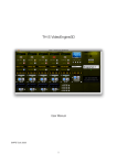
Fastmark 400 Series with
PALTM Print and Program Language
Barcode Label Printer
User’s Guide
Part No. 110039 A
AMT Datasouth Corp.
Corporate Headquarters
4765 Calle Quetzal
Camarillo, CA 93012
(805) 388-5799 PH
(805) 484-5282 FX
Charlotte Operation
4216 Stuart Andrew Blvd.
Charlotte, NC 28217
(704) 523-8500 PH
(704) 525 6104 FX
www.amtdatasouth.com
AMT Datasouth International
Unit B, Pinnacle 15
Gowerton Rd, Brackmills
Northampton, NN4 7BW
England
+44 1604 763394 PH
+44 1604 760661 FX
IMPORTANT SAFETY INSTRUCTIONS
AND OTHER NOTICES
!
This label printer complies with the requirements in Part 15 of FCC rules for a Class A
computing device. Operation of this equipment in a residential area may cause unacceptable
interface to radio and TV reception, requiring the operator to take whatever steps are
necessary to correct the interference.
!
Place the printer on a flat, firm and solid surface.
!
Do not place the printer near a heat source or near water.
!
Refer to the specification label on the bottom of this printer and ensure that your power
source exactly meets these requirements.
!
Do not open the printer during operation to avoid electrical shock.
!
Do not attempt to disassemble this printer if it malfunctions.
!
All rights are reserved. No part of this document may be reproduced or issued to third
parties in any form without the permission of AMT Datasouth.
!
The material in this document is provided for general information and is subject to change
without notice.
User's Guide 3
TRADEMARK CREDITS
Windows ® , MS-Word and MS-DOS are registered trademarks of Microsoft Corporation
PC ® is a registered trademark of International Business Machines
Centronics ® is a registered trademark of Centronics Corporation
PAL is a registered trademark of AMT Datasouth Corporation
COPYRIGHT NOTICES
© 2004 AMT Datasouth Corp. All rights reserved.
© 2003 Adobe Systems Incorporated
© 1996-2003 The FreeType Project. All rights reserved.
© 1993 Symbol Technologies, Inc.
© 1990 United Parcel Service of America, Inc.
COMPUTER SOFTWARE LICENSE AGREEMENT
This computer software, including display screens and all related materials, are confidential and
the exclusive property of AMT Datasouth Corp. They are available for limited use, but only
pursuant to a written license agreement distributed with this computer software. This computer
software, including display screens and all related materials, shall not be copied, reproduced,
published or distributed, in whole or in part, in any medium, by any means, for any purpose
without the express written consent of AMT Datasouth Corp.
© COPYRIGHT AMT Datasouth Corp. 2004 ALL RIGHTS RESERVED.
User's Guide 4
CONVENTIONS
Some of the procedures in this guide contain special notices that highlight important information:
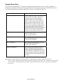
Note
Indicate information that you should know to help your
printer run properly and efficiently.
Caution
Indicate guidelines that, if not followed, can cause damage to
equipment.
Warning
Indicate a situation where there may be a danger to you.
Important Indicate that the associated material needs to be done to
ensure proper printer operation.
The use of the term's right and left assume that you are looking at the
front of the printer.
TECHNICAL SUPPORT
Please contact your local dealer first for technical support. Your dealer is knowledgeable about
driver installation, application software and general printer operation. If you still need factory
technical support after contacting your dealer, you may mail any problems through the E-mail
account, “www.amtdatasouth.com”. You can also get the most updated driver or application
from the web site “http://www.amtdatasouth.com”.
© Copyright 2004 by AMT Datasouth Corporation
First Edition: January 2004
User's Guide 5
Table of Contents
TABLE OF FIGURES.......................................................................................................8
INTRODUCTION..............................................................................................................9
MODEL OVERVIEW.....................................................................................................10
Models.......................................................................................................................... 10
Model Features............................................................................................................. 11
PALTM PRINT AND PROGRAM OVERVIEW ..........................................................12
Traditional Printing ...................................................................................................... 12
Legacy Data Stream Interpretation .............................................................................. 13
UNPACKING AND INSPECTION ...............................................................................14
INSTALLATION AND CONFIGURATION ...............................................................15
Finding a Location for the Printer................................................................................ 15
Connecting the Power Cord ......................................................................................... 16
Connecting the Printer to Your Host............................................................................ 17
Loading the Ribbon...................................................................................................... 18
Loading Media ............................................................................................................. 21
Loading Media when Peel and Present Option is Installed.......................................... 23
Calibrating Media Sensors ........................................................................................... 24
Printing the Configuration Label ................................................................................. 25
KEYPAD OPERATION .................................................................................................26
LED Description .......................................................................................................... 26
FEED Key Operation ................................................................................................... 27
Power up key functions................................................................................................ 27
Feature Management Mode.......................................................................................... 28
Setup Feature and Value List ....................................................................................... 29
PALTM PRINT LANGUAGE INTRODUCTION.........................................................33
Smooth Scalable Fonts................................................................................................. 34
Supported Bar Codes.................................................................................................... 34
PALTM Print and Program Label Tutorial.................................................................... 36
PALTM Print and Program Coordinate System ............................................................ 38
INTRODUCTION TO PALTM ADVANCED TOPICS................................................43
Advanced Overview..................................................................................................... 43
PALTM Print and Program Language Features............................................................. 44
Sample Demo Files ...................................................................................................... 45
Example of a Procedure defined in PALTM.................................................................. 46
Example of calling a Procedure from a host application ............................................. 46
Demo Label showing use of Print Utility Procedures.................................................. 47
Example of How to Define Label Formats .................................................................. 48
Example of calling Label Format from Host Application ........................................... 49
WINDOWS PRINTER DRIVER ...................................................................................50
Windows 2000 Driver Installation ............................................................................... 50
Windows XP Driver Installation.................................................................................. 54
Windows NT/9x Driver Installation............................................................................. 58
Using the Windows Driver To Produce PALTM Print Command Examples ............... 62
User's Guide 6
TROUBLESHOOTING AND MAINTENANCE.........................................................63
Printer Detected Errors................................................................................................. 63
User Detected Errors .................................................................................................... 65
Preventive Maintenance ............................................................................................... 66
Appendix A: GENERAL SPECIFICATIONS..............................................................69
Appendix B: INTERFACE SPECIFICATIONS ..........................................................70
Serial Interface ............................................................................................................. 70
Parallel (Centronics) Interface ..................................................................................... 71
Auto Interface Select.................................................................................................... 71
Appendix C: ASCII TABLE ...........................................................................................72
Appendix D: SELF TEST PRINT SAMPLE ................................................................73
Appendix E: HIDDEN SETUP FEATURES.................................................................74
Hidden Setup Feature and Value List .......................................................................... 74
Appendix F: UPDATING PRINTER FIRMWARE.....................................................76
Boot Mode Feature and Value List .............................................................................. 78
User's Guide 7
TABLE OF FIGURES
Figure 1 – Model and Serial Number Location............................................................................. 10
Figure 2 – Traditional Printing...................................................................................................... 12
Figure 3 – Legacy Data stream Interpretation............................................................................... 13
Figure 4 – Shipped with Printer .................................................................................................... 14
Figure 5 – Switches, Indicators and Connections ......................................................................... 15
Figure 6 – Power Connection........................................................................................................ 16
Figure 7 – Communication Cable.................................................................................................. 17
Figure 8 – Print Head Latches ....................................................................................................... 18
Figure 9 – Ribbon Holder Notch Location.................................................................................... 19
Figure 10 – Ribbon Loading.......................................................................................................... 20
Figure 11 – Open Media Access Cover......................................................................................... 21
Figure 12 – Media Spindle and Retainer Disk .............................................................................. 21
Figure 13 – Loading Media ........................................................................................................... 22
Figure 14 – Loading Media - Peal and Present ............................................................................. 23
Figure 15 – Configuration Print Sample ....................................................................................... 25
Figure 16 – Fastmark 400 Series Front Panel ............................................................................... 26
Figure 17 – FeatureMan Program.................................................................................................. 28
Figure 18 – Changing Features ..................................................................................................... 29
Figure 19 – Changing Feature Values ........................................................................................... 29
Figure 20 – Print Head Location ................................................................................................... 66
Figure 21 – Platen Roller............................................................................................................... 67
Figure 22 – Paper Compartment and Paper Sensor....................................................................... 68
User's Guide 8
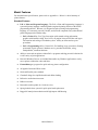
INTRODUCTION
The FM412 / FM403 are high-performance, low-cost Direct Thermal/Thermal Transfer labeling
printers featuring the PALTM Print and Program language.
PALTM Print and Program language is an interpretive page description language that allows
printers to move beyond the role of normal printers. In addition to supporting traditional text, bar
code, and graphics print sequences common to other printers, PALTM Print and Program language
also serves as a general purpose programming language. This combination of sequence based
printing commands and programming ability allows printers to provide unique solutions such as:
"
"
"
"
"
"
Intelligently read and interpret legacy data streams without host system programming
changes. Add or replace printers without changing the data streams. For example, this
tremendous flexibility permits changing from dot matrix text or card embosser’s to high
quality thermal printing with bar codes without changing the original data from the
host.
Store label formats and databases in the printer.
Store PALTM programs in the printer to create powerful stand-alone applications that
don't require a host or PC connection.
Create and store PALTM programs in the printer, which allow it to operate even if the host
system goes down.
Read data from an optional keyboard, scanner, scale, etc. and combine this data with
fixed formats to create powerful labeling solutions.
Perform math calculations and perform logical decisions within the printer.
PALTM Print and Program presents many exciting possibilities for rethinking the printer’s role
within any industry setting.
The User’s Manual will help you understand basic operations of the printer such as set-up,
installation, configuration and maintenance. For detailed information on the PALTM Print and
Program language, please refer to the PALTM Print and Program Reference Manual. Before
reading the manual you should first identify your printer model. The printer model name is
located on the bottom of the printer on its product label.
User's Guide 9
MODEL OVERVIEW
Models
The PALTM Print and Program versions of the Fastmark FM400 series are currently comprised of
2 models:
FM412 (200DPI)
FM403 (300 DPI)
These models are similar in many ways. The FM412 has a print head resolution of 200 DPI
versus 300 DPI on the FM403. Throughout this manual instructions and illustrations applying to
a particular model will be labeled accordingly otherwise the instructions apply to all models.
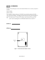
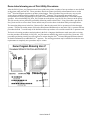
Note: The model number is printed on the compliance label attached to the bottom of the
printer. After un-packing please record the model number below for reference.
MODEL No:
SERIAL No:
Model No:
And
Figure 1 – Model and Serial Number Location
User's Guide 10
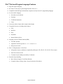
Model Features
For detailed feature specifications, please refer to Appendix A. Below is a brief summary of
printer features:
Standard Features
#
PALTM Print and Program Language. The PALTM Print and Programming Language is
a powerful printer language combining both exceptional printing abilities with flexible
programming abilities. Because it is designed as both a printing and programming
language, it is extremely powerful, flexible, and efficient compared to any other thermal
printer language on the market today.
•
PALTM Print ability: Free Type font engine with smooth scaling and rotation,
graphics with internal scaling, lines, boxes, all popular linear and 2D bar code types.
Full rotation and scaling of coordinate system. Ability to define and use print
procedures.
•
PALTM Programming ability: General I/O, file handling, loops, procedures, floating
point math, logical operators, database access, procedure definitions, string
manipulations, time/date functions.
#
Ability to store and run printer resident PALTM programs enabling powerful solutions for
a wide variety of print applications.
#
Powerful Windows Drivers are included that enable any Windows application to easily
access printer resident bar codes and fonts.
#
FeatureMan(ager) program for quick and easy printer configuration
#
All popular linear and 2D bar codes
#
Serial and Parallel ports standard
#
Clamshell design for simplified media and ribbon loading
#
Reflective media detection sensor
#
Ribbon out sensor
#
Removable media spindle for 1 inch core sizes
#
Spring loaded release system for quick print head replacement
#
Rugged all metal print mechanism with high impact ABS housing
User's Guide 11
PALTM PRINT AND PROGRAM OVERVIEW
Printers featuring PALTM Print and Program ability can be used in several ways in any given
environment. This section describes 3 common ways this advanced capability is used. Details of
how to take advantage of this advanced ability can be found in the PALTM Print and Program
Reference Manual. For help and assistance determining the best way to use this ability in your
situation, please consult your sales representative.
Traditional Printing
This environment represents the most common use of printers. Generally a single print job
(PALTM print sequences) generates a single label. In this role the PALTM Print and Program
interpreter accepts the print job, performs the required operator processing and prints the label,
tag, or ticket. Using a Windows driver in conjunction with a Windows application program is a
typical way to print in this environment. Alternatively, PALTM print sequences may also be
generated by any host application written to take advantage of this powerful language.
When a PALTM capable printer is used this way, no special “PALTM program” must be loaded on
the printer. Print sequences generated by a Windows driver or host programs are simply sent to
the printer resulting in print output just like traditional printers.
PAL Sequence
PAL
Interpreter
Printed
Document
PAL Sequence
Host System
PAL Printer
Figure 2 – Traditional Printing
User's Guide 12
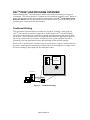
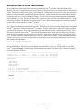
Legacy Data Stream Interpretation
PALTM Print and Program capable printers uniquely address applications where upgrading to
modern cost effective technology is desired. Often cost-prohibitive software reprogramming to
change a data stream prevents an organization from moving to new printing technologies.
Using a PALTM Print and Program capable printer solves this problem. In this case a PALTM
program is written which interprets a data stream normally sent to the legacy device being
replaced. This program is stored on the printer and is automatically executed each time the
printer is powered on. This program is able to produce a new label format based on this legacy
data. Even though the host computer is sending the exact same legacy data to the printer, the
label format can be completely different. For example the new format may include bar codes,
scaled and/or rotated fonts, lines, logo's etc. Even though the legacy device being replaced does
not support these print abilities, the new label format can.
For example, text only outputs such as produced by a dot-matrix printer or card embosser may
now be presented in a more functional format. Information in the data stream can be reformatted
into any size font in any rotation, or even printed as bar code. This example demonstrates how
PALTM Print and Program capable printer can replace a legacy print device with no host software
changes required.
PAL Data Stream
Application
Legacy Data
Stream
PAL
Interpreter
Printer
Flash Memory
Printed
Document
Legacy Data
Stream
Host System
PAL Printer
Figure 3 – Legacy Data stream Interpretation
User's Guide 13
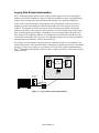
UNPACKING AND INSPECTION
This section is provided to assist you in removing the printer from the shipping container and
setting it up in the application environment. Inspect the shipping carton and contact the carrier
directly to report any suspected damage.
1. With the shipping container in the upright position, remove the top foam packing piece.
2. Carefully, lift the printer straight up out of the box.
3. Remove the printer from the plastic bag and place the printer on a flat stable surface.
4. Remove the power supply from the separate enclosed box.
5. Remove the accessory kit and supplies.
6. Inspect the shipping container and the printer for any damage that may have occurred
during shipping.
Note: Save the box and all packing materials for future use, in the event the
printer needs to be shipped. Units returned for service in nonapproved packaging may void the warranty or increase repair costs
due to shipping damage.
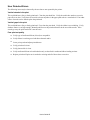
Verify that the printer box contains the following materials when unpacking:
a.
b.
c.
d.
e.
f.
g.
Printer
Quick Start Up Guide
Media spindle (with retainer disk)
Power adapter (AC to AC)
CD or disks with User's manual and Windows drivers
A sample media roll (not pictured)
A sample ribbon roll and a take-up ribbon core (not pictured, Thermal Transfer printers
only)
Power Adapter
Printer
Quick Start Up Guide
Media Spindle
CD or Diskette
Figure 4 – Shipped with Printer
User's Guide 14
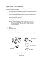
INSTALLATION AND CONFIGURATION
Finding a Location for the Printer
Determine a suitable location for the printer and power supply brick with the following
requirements:
•
Find a flat stable surface with sufficient clearance to allow for interface cables and media
loading.
•
The location should be near the host or terminal. Consider the distance between the host
and printer for the communication cable (serial or parallel cable).
•
The location should be free from excessive direct sunlight, temperature, humidity, dust,
dirt, and debris.
•
The location should be near a grounded AC power receptacle wired in compliance with
local ordinances.
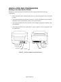
Serial Port
Power LED
Power Jack
Ready LED
Feed button
Parallel Port
On Switch
Figure 5 – Switches, Indicators and Connections
User's Guide 15
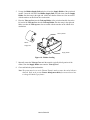
Connecting the Power Cord
1. Make sure that the source voltage matches the input voltage of the power adapter.
Caution: Incorrect source voltage could cause damage to the printer and/or the
power adapter.
2. Ensure the printer power switch is Off, “O”.
3. Connect the power plug to the Power Jack on the back of the printer. Avoid touching
the parallel connector.
4. Connect AC power plug to a suitable AC source.
5. Connect either a Centronics Parallel or RS-232 Cable.
Figure 6 – Power Connection
User's Guide 16
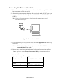
Connecting the Printer to Your Host
1. You can connect the printer with any standard Centronics cable to the parallel port of the
host computer or network print server.
2. Alternatively, you can connect the printer with a serial cable to the RS-232C port of your
computer or terminal. (For PC compatibles, the RS-232C port is COM1, COM2 or
COM3.)
Note: Using the Centronics interface allows for higher communication speed
than the serial interface.
Figure 7 – Communication Cable
3. If you use the serial port with your own cable, refer to the Appendix B and check the pin
connection.
Caution: Pin 9 on the serial port is directly connected to +5volts DC. Do not
connect this pin in your cable.
4. Be sure that the speed (baud rate) and protocol are the same between printer and host.
Note: Refer to the section Feature Management Mode for instructions on how to
change communication features.
Default serial port settings:
Speed (baud rate)
9600
Data format
1 start bit, 8 data bits and 1 stop
bit.
Parity
None
Handshaking (Flow control) XON/XOFF and RTS/CTS
User's Guide 17
Loading the Ribbon
Thermal Transfer Media only
If Direct Thermal Media is used, skip to the section Loading Media.
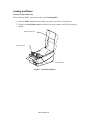
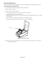
1. Open the Media Access Cover by lifting it up until it rests in the vertical position.
2. Slide the two Print Head Latches toward the back of the printer to unlock the print head
module.
Media Access Cover
Print Head Latch
Print Head Latch
Figure 8 – Print Head Latches
User's Guide 18
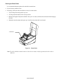
3. Raise the print head module to the vertical position.
4. Verify that the Ribbon Supply Core and the Take-up Core have two slots on the left
side of the core when the ribbon is positioned to go into the printer. These slots will be
mated to the notches on the Left Ribbon Holders.
Note: The notches are the drive mechanism for the ribbon. If the slots in the core are not
present or if they are in the wrong position, contact your ribbon supplier to obtain
a correct ribbon.
Notch
Figure 9 – Ribbon Holder Notch Location
User's Guide 19
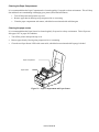
5. Unwrap the Ribbon Supply Roll and place it into the Supply Holder of the print head
module. Insert the left end of the Ribbon Supply Roll (end with slots) into the Supply
Holder first then snap in the right end. Make sure that the ribbon core slots are mated
with the notches on the ribbon drive mechanism.
6. Place the Take-up Core into the Take-up Holder of the print head module. Insert the
left end of the Take-up Core into the Take-up Holder first then snap in the right end.
Make sure that the Take-up core slots are mated with the notches on the ribbon drive
mechanism.
Take-up Holder
Ribbon
Supply Roll
Supply Holder
Figure 10 – Ribbon Loading
7. Manually rotate the Take-up Core until the transfer (typically black) portion of the
ribbon, from the Supply Holder start onto the Take-up Core.
8. Close and latch the print head module.
Note: The printer must be set to the Thermal Transfer mode to ensure the end of ribbon is
detected. Refer to the section Feature Management Mode for instructions on how
to change the Media Type feature.
User's Guide 20
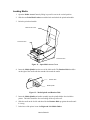
Loading Media
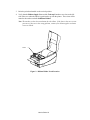
1. Open the Media Access Cover by lifting it up until it rests in the vertical position.
2. Slide the two Print Head Latches toward the back and unlock the print head module.
3. Raise the print head module.
Media Access Cover
Print Head Latch
Print Head Latch
Figure 11 – Open Media Access Cover
4. Insert the Media Spindle into the core of the label media. The Retainer Disk should be
on the right of the media with the smooth side toward the media.
Retainer Disk
Media Spindle
Figure 12 – Media Spindle and Retainer Disk
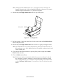
5. Insert the Media Spindle and media assembly into the spindle holder slots inside the
printer. The labels should be face out feeding off the top of the roll.
6. Slide the media to the far left and then slide the Retainer Disk up against the media until
it is snug.
7. In the base of the printer locate the Right and Left Media Guides.
User's Guide 21
Note: The Right and Left Media Guides are ‘U’ shaped parts that are located at the
bottom of the paper path. Only the Right Media Guide can be moved. The media
should be snugly positioned in the ‘U’ portion of the guides.
8. Slide the adjustable Right Media Guide to the far right of the printer.
Media guides
Figure 13 – Loading Media
9. Pull out 6 inches of media and thread the end of the media under the Left Media Guide
and over the platen roller.
10. Slide the adjustable Right Media Guide to the left until it is gently touching the media.
Note: If the Media Guides are too loose the media may pull out from them and result in
false media out errors. If the Media Guides are too tight the media may buckle and
result in media jams.
11. Close and lock the print head module by pressing firmly until the right and left Print
Head Latches snap shut.
12. Close the Media Access Cover.
Note: The first time media is installed, the Media Sensor must be calibrated. After the
first calibration no further calibration is required unless the media type (length,
color, backing material, etc.) is changed or irregular feeding occurs. Refer to the
section Calibrating Media Sensors for instructions on how to calibrate the media
sensor.
User's Guide 22
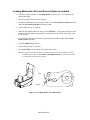
Loading Media when Peel and Present Option is Installed
1.
Follow the same procedures in "Loading Media" up until step 11, close and lock the
print head module.
2.
Peel off 6 inches of labels from its backing.
3.
Thread the label backing over the platen roller, over the Peel and Present Bar then back
under the Peel and Present Bar towards the platen.
4.
Turn on the power to “1” position.
5.
With the print head module still open, press the FEED key. The printer will advance the
backing. Once the label backing comes out of the front of the printer, turn off the power
to “O” position.
6.
Close and lock the print head module by pressing firmly until the right and left Print
Head Latches snap shut.
7.
Close the Media Access Cover.
8.
Turn on the power to “1” position.
9.
Press the FEED key to feed out the first label in the printer.
Note: For the Peel and Present mode to function properly the Present Sensor must be
enabled. Refer to the section Feature Management Mode for instructions on how
to change the Present Sensor feature.
Label
Backing
Figure 14 – Loading Media - Peal and Present
User's Guide 23
Calibrating Media Sensors
Important: The first time media is installed, the Media Sensor must be calibrated. After
the first calibration no further calibration is required unless the media type
(length, color, backing material, etc.) is changed or irregular feeding occurs.
1. Ensure the printer is powered off.
2. Verify that the media is properly loaded and routed as detailed in Loading Media
section.
3. While pressing and holding the FEED key, power on the printer.
4. The READY LED (right most LED) will blink twice.
5. Continue to hold the FEED key until the printer begins to feed the media.
6. Release the FEED key.
7. When feeding stops the printer has completed the Media Sensor Calibration procedure.
The print head module can be opened and the media may be manually reversed back to
the first label to save label stock.
8. After closing the print head module, press the FEED key again to re-align the media to
the top of the label.
Note: For the Calibration procedure to function properly the proper Media Sensing Type
(Gap or Black Bar) must be selected. This setting may be made using the
FeatureMan program supplied.
User's Guide 24
Printing the Configuration Label
1. Ensure the printer is powered off.
2. Verify that the media is properly loaded and routed as detailed in Loading Media
Section.
3. While pressing and holding the FEED key, power on the printer.
4. The READY LED (right most LED) will blink twice.
5. Continue holding the FEED key while the media feeds for several label lengths.
6. When the printer begins to print the configuration label you may release the FEED key.
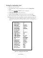
Note: Media width at least 3 inches wide should be used for the configuration print out. The
following figure is an example configuration printout. The feature settings on your
printer may vary based on any setup changes made or firmware version installed in the
printer.
Media Type
Media Sensing
Sensor Threshold
Media Length
Media Width
Present Distance
Present Sensor
Vert Print Align
Horz Print Align
Vert Size Adjust
Print Darkness
Print Speed
Interface Select
COM1: Baud Rate
COM1: Parity
COM1: Data Bits
COM1: Handshake
COM1: PAL Xmit
Emulation Mode
Date
Time
Daylight Saving
Firmware Rev.
PAL Boot Drive
Max Media Length
Keypad Lockout
Label Count
Drive A: (131072)
Drive B: (262144)
Drive C: (0)
Drive D: (32768)
Thermal Transfer
Gap
70
4.00 Inches
4.00 Inches
+0.24 Inches
Disabled
0.00 Inches
+0.20 Inches
0
-8
6
Auto Select
9600
None
8
RTS & XON
Disabled
PAL Emulation
Not Installed
Not Installed
Disabled
110156 A
Auto Detect
12.00 Inches
Disabled
582
Empty
Empty
Empty
Empty
Figure 15 – Configuration Print Sample
User's Guide 25
KEYPAD OPERATION
Power LED
Ready LED
Feed Key
On Switch
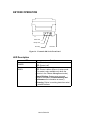
Figure 16 – Fastmark 400 Series Front Panel
LED Description
LED
❍
POWER
❍
READY
Function
ON: Printer is on
OFF: Printer is off
ON: Printer is online
OFF: Printer is either offline or in setup mode.
(This mode is only available only when the
printer is in the Feature Management mode.)
Steady Blinking: System error occurred.
(Refer to the section Trouble Shooting and
Maintenance for information on errors.)
Flickering: Printer is receiving data from serial
or parallel interface
User's Guide 26
FEED Key Operation
Pressing the FEED key causes the printer to feed one label. During error conditions, when the
READY LED is blinking, the FEED key will cancel the error.
Power up key functions
Several different functions can be selected by holding the FEED key down during power up. The
table below indicates the function performed when the FEED key is pressed and held for
different lengths of time during power up.
FEED Key Duration
Power Up Function
FEED key is released The printer enters the Feature Management
after the READY LED mode. Placing the printer in this mode while
flashes once
running the FeatureMan program, included on
the product CD, provides an easy way to
configure printer features.
FEED key is released PALTM program loaded: When a PALTM
after the READY LED program is loaded it runs automatically on
flashes twice
power up. Pressing this key bypasses the
program and places the printer in normal mode.
The most common reason to bypass a PALTM
program on power up is to allow a new or
updated program to be loaded in the printer.
No PALTM program loaded: No function.
FEED key is released The printer performs a Media Calibration test,
after
the
calibration which adjusts the sensor sensitivity, measures
sequence starts
the label length, and measures gap/notch/hole.
These values are stored in non-volatile memory.
FEED key is held down The printer generates a configuration label
until the printer starts showing current feature settings, firmware
printing the configuration revision, and PALTM drive storage capacity.
label
User's Guide 27
Feature Management Mode
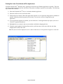
The printer can be easily configured using the Feature Management Mode. When this mode is
enabled the printer uses the serial interface to communicate feature settings to the FeatureMan
program running on the PC. The printer remains fully functional while in the Feature
Management Mode with the exception that the serial interface is dedicated to the FeatureMan
program and cannot be used for host communication. Once features such as baud rate or media
type are configured, the values are retained in non-volatile memory (NVM). Refer to the Setup
Feature and Value List for a description of the printer features and their valid range of values.
If the serial interface is used for host communication the printer must be powered off after con
figuring the features, reconnected to the host, and powered back on to resume normal printing.
If the parallel interface is used for host communication the printer may be operated directly from
the Feature Management Mode. In this mode of operation the FeatureMan program will
continue to provide front panel control and will display all On line, Off line, PAL programming
and error messages.
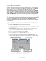
Use the following procedure to enable the Feature Management Mode and configure the printer
features.
1. Install the FeatureMan program included on the product CD.
2. Attach the printer to the PC using the included serial cable. Be sure to note which COM
port is used on the PC.
3. Run the FeatureMan program on the PC. Select the COM port used as noted in the
previous step. The simulated printer LCD should display “Connecting”.
4. Power on the printer while holding down the FEED key.
5. Release the FEED key after the READY LED flashes once.
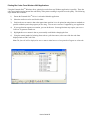
6. The printer should now begin communicating with the FeatureMan program. The
printer will run through a series of power up messages ending with an Off line message.
Displayed messages from printer
Set to match the com port to
which the printer is connected.
Online/Offline button
Press Display Up/Down to
enter setup mode.
Figure 17 – FeatureMan Program
7. Click the Display Up/Down buttons to enter the setup mode.
User's Guide 28
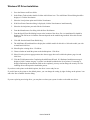
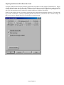
8. Continue to click the Display Up/Down buttons as needed until the feature to be modified
is displayed on the top line of the display. (ex. Baud Rate)
Figure 18 – Changing Features
9. Click the Enter button to enter the Change mode. The top line of the display should start
blinking to indicate the Change mode is active.
10. Click the Display Up/Down buttons as needed to select the new value.
11. Click the Enter button to save the new value and exit the Change mode. The top line of
the display should no longer be blinking.
Figure 19 – Changing Feature Values
12. When all features have been adjusted, click the Online/Offline button and the printer is
now ready for use. If a PAL program is loaded, the message now displayed on the
simulated printer LCD will vary depending on the program.
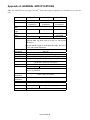
Setup Feature and Value List
User's Guide 29
FEATURE NAME
VALUE RANGE
DESCRIPTION
Media Type
[ Direct Thermal, Thermal
Transfer ]
Set to Thermal Transfer if ribbon
is used.
Media Sensing
[Gap, Continuous, Black Bar ]
Set to match media sensing
method.
Calibrate Media
(Form Length / Gap Length)
automatically displayed and are
not adjustable from this feature.
Click the Enter button to initiate
the media calibration. The
detected media length and Gap
are displayed. Not required
when Media Sensing is set to
Continuous
Sensor Threshold
[ 0-255]
Automatically set by Calibration
mode.
Media Length
[ 0.25 - 12.00] (Inches)
Automatically set by Calibration
mode
Media Width
[ 0.5 - 4.05] (Inches, 4602)
Set to media width used.
[ 0.5 - 4.25] (Inches, 4603)
Present Distance
[ 0.00 - 1.00 ] (Inches)
Adjust to position label at tear
bar. If optional Peel and
Present kit is installed, this
feature will specify how far the
label is presented. After setting
this feature the printer will feed
to the top of the next label.
Present Sensor
[Enable, Disable]
This feature controls the
operation of the optional present
sensor. When installed and
enabled, the printer suspends
printing after each label until it is
removed by the operator. This
is typically used when the peel
and present option is installed
but could also be used with the
tear bar.
User's Guide 30
Setup Feature and Value List (continued)
Vert Print Align
[ -0.50 - +0.50 ] (Inches)
Adjust to move printed image up
or down on label. Positive
values move image up.
Negative values move image
down. After setting this feature
the printer will feed to the top of
the next label.
Horz Print Align
[ 0.00 - 1.00 ] (Inches)
Adjust to move printed image
left or right. Larger values move
the image to the right.
Vert Size Adjust
[ -60 - + 60 ]
Vertically expands or
compresses print image.
Negative values are
compressed, positive values are
expanded.
Print Darkness
[ -12 - +12 ]
Adjust for optimal print
darkness. Positive values are
darker.
Print Speed
[ 2, 3] (IPS)
Adjusts print speed.
Interface Select
[ Parallel Only, Serial Only, Auto
Select ]
Selects active interface while
ignoring non-selected interface.
Setting to Auto Select enables
both interfaces and performs
automatic port arbitration.
COM1: Baud Rate
[ 1200, 2400, 4800, 9600, 14400,
19200, 38400, 57600 ]
Set to match host.
COM1: Parity
[ None, Odd, Even ]
Set to match host.
COM1: Data Bits
[ 7, 8 ]
Set to match host.
COM1: Handshake
[ RTS, XON/XOFF, RTS & XON,
None ]
Set to match host.
COM1: PAL Xmit
[ Enabled, Disabled ]
Enables or disables transmission of PALTM messages
over serial interface.
User's Guide 31
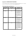
Setup Feature and Value List (continued)
Emulation Mode
[ PAL, ASCII, Hex, Display ]
Selects active emulation. ASCII
emulation is a basic text
emulation. Hex and Display
emulations are used for printing
data in a format that shows the
exact data being received by the
printer. This is useful trouble
shooting communications or
host programming issues.
Date
[MM/DD/YYYY]
If RTC option is installed, this
feature allows the date to be set.
Click the Enter button to select
Month/Date/Year to modify.
Click the Display Up/Down
buttons to modify then click the
Enter button to select next
parameter. When the full date is
displayed the change is
complete.
Time
[HH:MM:SS]
If RTC option is installed, this
feature allows the time to be set.
The hour is set in 24 hour format
(0-23). Click the Enter button to
select Hour:Minutes:Seconds to
modify. Click the Display
Up/Down buttons to modify then
click the Enter button to select
next parameter. When the full
time is displayed the change is
complete.
[Enabled, Disabled]
If RTC option is installed, this
feature specifies whether the
time is automatically updated for
Daylight Savings time.
Daylight Savings
Print Features
N/A
Click the Enter button to print
the feature list.
Print Test Label
N/A
Click Enter button to print a test
label.
Firmware Rev.
N/A
Firmware P/N and revision
User's Guide 32
PALTM PRINT LANGUAGE INTRODUCTION
This section provides an introduction to basic PALTM print language abilities including fonts and
bar codes. For information regarding PALTM programming abilities, creating stand-alone
applications, and other advanced topics please refer to the Fastmark PALTM Print and Program
Reference Manual.
The Windows driver included with the printer is an excellent method to generate PALTM print
sequence based commands. For example, to easily determine which PALTM print sequences are
used to produce a given label format, the Windows driver can be used to generate the necessary
commands. In this case the basic label format would be generated using a Windows program,
then the "print to file" option is selected. This will produce a file containing the exact commands
required to produce a given label format. Using this file as a template a programmer can
incorporate the necessary commands into the host or Windows based application. For more
information refer to the section titled Using the Windows Driver To Produce PALTM Print
Command Examples.
User's Guide 33
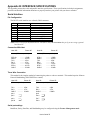
Smooth Scalable Fonts
PALTM Print and Program capable printers allow a font to be selected by name, scaled, rotated,
and placed on the drawing service. The table below lists the unique names used to select the
fonts and a print sample showing a specific point size. Please refer to the PALTM Print and
Program Reference manual for detailed information on the use of fonts.
Font
PALTM
Identifier
Point
Size
Sans Serif
14
SansSerif
OCRB
10
OCRB
Sample
Table 1 – PALTM Font List and Samples
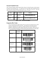
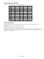
Supported Bar Codes
PALTM Print and Program capable printers allow a bar code to be selected by name, rotated
if needed, and placed on the drawing surface. All popular linear and 2D bar codes are
supported. Depending on bar code type, a number of parameters may be adjusted, as
needed for example human readable, height, X dimension, check digits. Please refer to the
PALTM Print and Program Reference manual for detail information on the use of bar codes.
Bar Code
PALTM
Sample
Identifier
Code 39
/Code39
Code 93
/Code93
Code 128
/Code128
A, B and C
Interleave
/I2of5
2 of 5
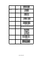
User's Guide 34
UPC-A
/UPCA
UPC-E
/UPCE
EAN-8
/EAN8
EAN-13
/EAN13
Codabar
/Codabar
Postnet
/Postnet
Maxicode
/Maxicode
MSI Plessy
/MSI
PDF-417
/PDF417
Table 2 – PALTM Bar Code List and Samples
User's Guide 35
PALTM Print and Program Label Tutorial
This Label Tutorial provides instructional steps showing the basic commands needed to create
labels using PALTM Print and Programming Language. This section covers some of the most
common sequences used to print fonts, bar codes, lines etc. Each label introduces a basic concept
and builds on the preceding label. Upon completion of the tutorial, a label consisting of text in
two orientations, a line, a box and a bar code will be covered.
The examples may be created using a text editor and saved for subsequent transmission to the
printer using the FlashWiz program found on the product CD, using the DOS copy command, or
the send file command that is implemented in most terminal emulators.
For a deeper understanding of the concepts behind the sample label and the programming
capabilities of PALTM, please refer to the PALTM Pint and Program Reference Manual.
Note: The PALTM Print and Program command interpreter is case sensitive! All commands must
be entered exactly as shown in the examples.
User's Guide 36
Printing Text on a Label
PALTM Command Sequences
Label Output
/Sans12.00pt findfont
12 scalefont
setfont
72 72 moveto
(Hello World!) show
1 _showpages
Hello World!
1"
1"
Purpose: Demonstrate how to print simple text on a label.
findfont - Establish the font to use
The fontname is preceded by a “/”. In this example, a Sans Serif 12 point font was chosen. See
Table 1 for supported fonts.
scalefont – Scale the selected font’s size in points
It is typical to use the value indicated in the selected font. In this example, since Sans12.00pt was
the selected font, the scaling was set to 12. Optionally, the command may be used to scale the font
to a different size (e.g. 13 or 11)
setfont - Set the current font to the scaled font defined by the scalefont operator
This font will be used for all subsequent text unless another font is chosen.
moveto - Position the drawing cursor at the desired location
Moves the cursor position 1 inch to the right and 1 inch from the bottom (see box on next page for
description of coordinate system).
show – Place the text on the label
The text to be printed is enclosed by parentheses. The lower left-hand corner of the text is placed
at the current cursor position. In this example the cursor position is established with the moveto
command as described above.
_showpages - Print the created label
The “1” in the example indicates that one label is to be printed. If printing 10 labels, the
command would be 10 _showpages.
User's Guide 37
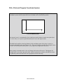
PALTM Print and Program Coordinate System
The default coordinate system used by PALTM Print and Program Language is a traditional Cartesian
coordinate system with the origin at the lower left-hand corner of the drawing surface:
y
(0,0)
x
PAL Coordinate System
An internal “cursor” is maintained by PALTM that keeps track of where to put the next print object,
i.e. text or lines, etc. At power up this internal cursor is set to the origin or (0,0).
The default unit used for measuring distance in this coordinate system is the point. A point is a
common typographical unit equivalent to 1/72”. There are 72 points to an inch. The example sets the
“cursor” to 72,72 to place text at a point 1 inch to right of the origin and 1 inch above.
Some printing commands such as show will change the location of the cursor. This happens for
example after a text string is put on the label. After the text has been written to the label, the cursor
is updated to point to the end of the text in preparation for the next string.
User's Guide 38
Printing a Line
PALTM Command Sequences
Label Output
/Sans12.00pt findfont
12 scalefont
setfont
72 72 moveto
(Hello World!) show
72 68 moveto
144 68 lineto
stroke
1 _showpages
Hello World!
1"
1"
Purpose: Demonstrate drawing lines on a label. This example underlines the “Hello World!”
text from the previous example.
moveto - Position the drawing cursor at the desired location
The line will be positioned near the same location as the text, a bit lower in the y direction to
allow for a small space between the bottom of the text and the line. This example uses the value
68, 4 points below the text (4/72 inches).
lineto – Set the dimensions for the line
The line will be drawn from the current position (72,68) to the position set by the lineto (144,68).
The vertical position did not change resulting in a horizontal line stretching between the x
locations of 72 and 144.
stroke – Draw the line
Actually draws the line specified by the lineto command.
User's Guide 39
Printing a Box
PALTM Command Sequences
Label Output
/Sans12.00pt findfont
12 scalefont
setfont
72 72 moveto
(Hello World!) show
72 68 moveto
144 68 lineto
30 30 moveto
258 30 lineto
258 258 lineto
30 258 lineto
closepath
2 setlinewidth
stroke
1 _showpages
Hello World!
1"
1"
Purpose: Demonstrate the drawing of a rectangular box. This example builds on the previous
example by drawing a frame around the label. A 4” x 4” (288 points x 288 points) label is used in
this example. The frame will be placed within 30 points of the edge of the label.
moveto - Position the drawing cursor at the desired location
This example assumes a 4” x 4” label (288 points x 288 points). A frame is drawn by moving to
the starting point with the moveto operator.
lineto - Set the dimensions for the line
Forms three sides of the box with three separate lineto operators.
closepath - Close the shape
A box is drawn by drawing 3 sides of the box with the lineto operator followed by closepath,
which closes the box by drawing the last line. It is important to use this operator to close a shape
since the imaging algorithms may or may not actually close the shape due to rounding errors in
the algorithm.
setlinewidth - Set the width of the lines
The width is set in points. In this example, the line width is set to 2 points. The line width value
will remain the effective value for all lines until changed.
User's Guide 40
Rotate a Text Object
PALTM Command Sequences
Hello World!
Label Output
Hello World!
1"
1"
/Sans12.00pt findfont
12 scalefont
setfont
72 72 moveto
(Hello World!) show
72 68 moveto
144 68 lineto
30 30 moveto
258 30 lineto
258 258 lineto
30 258 lineto
closepath
stroke
72 90 moveto
90 rotate
(Hello World!) show
-90 rotate
1 _showpages
Purpose: Demonstrate how to rotate text. This example builds on the previous example by
placing another instance of “Hello World!” rotated 90 degrees.
moveto - Position the drawing cursor at the desired location
The text will be located at the same x position and slightly higher in the y direction relative to the
previous text.
rotate - Rotate the coordinate system
In this example the coordinate system is rotated 90 degrees. Since the entire drawing surface is
being rotated, it is important to reset the rotation by the same amount in the opposite direction (90 degrees) after text has been placed.
show - Place the text on the label
The text to be printed is enclosed by parentheses. The lower left-hand corner of the text is placed
at the current cursor position.
User's Guide 41
Printing a Bar Code
PALTM Command Sequence
Hello World!
Label Output
*BARCODE123*
Hello World!
1"
1"
/Sans12.00pt findfont
12 scalefont
setfont
72 72 moveto
(Hello World!) show
72 68 moveto
144 68 lineto
30 30 moveto
258 30 lineto
258 258 lineto
30 258 lineto
closepath
stroke
72 90 moveto
90 rotate
(Hello World!) show
-90 rotate
100 100 moveto
(BARCODE123) /Code39 _barcode
1 _showpages
Purpose: Demonstrate how to print a bar code. This example builds on the previous example by
placing a bar code near the center of the label.
Moveto - Position the drawing cursor at the desired location
Position cursor at desired location for bar code.
(BARCODE123) – String object defining the barcode content.
The parentheses delimit the text string and are not part of the barcode. The actual bar code value
in this case is BARCODE123, i.e. parentheses not included.
_barcode – Place the specified bar code on the label
The type of bar code is referenced by a ‘/’ followed by the name of the bar code type. For a list of
supported bar codes, see Table 2.
User's Guide 42
INTRODUCTION TO PALTM ADVANCED TOPICS
Advanced Overview
As previously mentioned the PALTM Print and Program Language is both a powerful printing and programming
language. For example the included Windows driver takes advantage of the powerful printing portion of the
language. Your VAR or internal programming staff may take advantage of some of the programming abilities. The
fact that a single printer language supports both capabilities is unique. PALTM Print and Program enabled printers can
be used in many ways not supported by traditional printers.
A full technical description of the PALTM Print and Program Language is beyond the scope of this manual. Please
refer to the PALTM Print and Program Language Reference manual for details.
For assistance developing PALTM applications or solutions for your unique labeling requirements, please contact your
sales representative.
User's Guide 43
PALTM Print and Program Language Features
#
Page Description Language
#
No control Codes (easy to pass through networks, filters, etc.)
#
Compatible with midrange and mainframe computers and any host or PC programming language.
#
Is an executable language
"
Procedures can be defined
"
Functions
"
Conditional statements
"
Loops
#
Can create and use simple and/or complex data formats
#
Can gain full access to resident printer features
#
#
#
"
LCD
"
Interfaces
"
Keys
"
Keyboards
"
Internal Memory drives
Language is Reverse Polish Notation (RPN)
"
Like HP Calculator
"
Arguments first then operators i.e. 4 6 + versus 4 + 6 =
"
Data passed on stack
PALTM Coding Structure is Free Form
"
All operators, objects, and data are separated by whitespace: CR, CR+LF, LF, LF+CR, Tab, or Space.
"
Extra lines in data are OK
"
Comments may be added proceeded by % character.
Powerful Object handling
"
Basic Objects: Integers, Fixed-Point, Boolean
"
Composite Objects: String, Name, Arrays, Dictionaries, Procedures
User's Guide 44
Sample Demo Files
Several text files containing PALTM examples are included on the product CD. These files show programming
techniques and examples, which may be incorporated into host or PC programming or just used as reference. Each
text file includes descriptive comments within the file. Below is a description of each file:
File Name
Description
Pal_Procs_and_Formats.txt
This file contains a number of print utilities
written as PALTM procedures. These were
designed to illustrate common printing
commands and the use of common PALTM
operators. These utilities once defined may
simplify common printing functions. Also
within this file is a number of sample label
Formats. These label formats make extensive
use of the print utilities defined in this file.
These formats show how once a label format is
defined it may be used by simply listing the
variable data and calling the format name.
Format_Demo.txt
This file shows how to call up and use the label
formats defined in the file
Pal_Procs_and_Formats.txt
Proc_Demo.txt
This file shows how to call up and use the print
utility procedures defined in
Pal_Procs_and_Formats.txt.
Proc_Template.txt
This file shows the format of the calls to the
print utility procedures defined in
Pal_Procs_and_Formats.txt
Format_Template.txt
This file can be used to define new label
formats. It includes all the print utilities
defined in Pal_Procs_and_Format.txt. Once
new label formats are defined, this file may be
copied to the printer and the new formats may
be called up and used as demonstrated by the
other files.
Note: Before using any of the print utility procedures or label format procedures defined in the text file
Pal_Procs_and_Formats.txt, this file must be copied to the printer so that the PALTM interpreter can parse these
new procedures. The FlashWiz utility included on the product CD may be used to copy this file to the printer
prior to use.
User's Guide 45
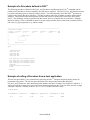
Example of a Procedure defined in PALTM
The following procedure is defined in Pal_Procs_and_Formats.txt and illustrates how PALTM commands may be
combined in a procedure to create a completely new function or capability. The file Pal_Procs_and_Formats.txt must
be copied to the printer prior to using any of these utilities. The following utility shows how PALTM operators are
used to create a simple Box draw procedure. This Box procedure makes use of another procedure defined called
inchtopts. This procedure takes measurements in inches and converts to points which is the native unit used by
PALTM. The advantage of using a procedure like this to draw boxes is to simplify the use of the PALTM language.
Instead of issuing 7 PALTM commands to draw a box, this single procedure may be called with 5 parameters (lower
left corner x,y, upper right corner x,y, and line width).
%========================================================================
% Box draw procedure
% Usage:
botX(in.) botY(in.)
topX(in.)
topY(in.)
lwidth(in.) Box
% Example: 0.1
0.1
3.9
1.9
0.01
Box
%
%
(topX, topY)
%
+--------*
%
|
|
%
|
|
%
*--------+
%
(botX, botY)
%
%========================================================================
/Box
{
/lwidth exch def
/topY exch def
/topX exch def
/botY exch def
/botX exch def
botX inchtopts botY inchtopts
botX inchtopts topY inchtopts
topX inchtopts topY inchtopts
topX inchtopts botY inchtopts
closepath
lwidth inchtopts setlinewidth
stroke
moveto
lineto
lineto
lineto
} bind def
Example of calling a Procedure from a host application
The two lines preceded by % are comment lines ignored by the PALTM interpreter and don't actually need to be
transmitted to the printer. The last line shows the actual call to the procedure named Box defined in
Pal_Procs_and_Formats.txt. Note that floating point numbers must have a leading 0 for example 0.1 instead of .1.
Also note while the example below uses many spaces between parameters, this is only for clarity and only a single
whitespace character is actually needed i.e. 0.1 0.1 3.9 1.9 0.01 Box would also work.
% Box draw
% botX(in.) botY(in.)
0.1
0.1
topX(in.) topY(in.) lwidth(in.) Box
3.9
1.9
0.01
User's Guide 46
Box
Demo Label showing use of Print Utility Procedures
After the file Pal_Procs_and_Formats.txt has been copied to the printer, a number of new procedures are now defined
in the printer (until powered off). These procedures have been written specifically to demonstrate how to use the
PALTM Print and Program operators to produce printed output. These procedures also provide easy ways to print
various objects without actually needing to know the PALTM language. The print utility procedures may be
incorporated into custom programming or just used as reference to better understand the PALTM Print and Program
operators. After downloading Pal_Procs_and_Formats.txt to the printer, copy the file Proc_Demo.txt to the printer.
This file uses the various print utility procedures defined to produce a demo label. Using a text editor, open the file
Proc_Demo.txt file to see how these various utilities may be used as shown in the demo label print sample below.
The interesting thing to note in the Proc_Demo.txt file is that the only actual PALTM operator used is the showpage
operator. The other procedure names used such as Printfont and Printbarcode are not native PALTM operators but new
procedures defined. A careful study of the definition of these procedures will reveal the actual PALTM operators used.
The basics of creating procedures and using them in the PALTM language should start to make sense after reviewing
how the procedures are defined (in Pal_Procs_and_Formats.txt) and how they can be used (in Proc_Demo.txt). New
procedures performing virtually any task can now be written using the PALTM Print and Program Reference manual
for detailed information on additional PALTM operators. The existing procedures may be modified as needed to meet
requirements or completely new procedures may be written.
User's Guide 47
Example of How to Define Label Formats
The example below shows how a label format can be defined as a PALTM procedure. This label format called
Mailing_Label uses 5 variables. Notice how the variables are defined in reverse order compared to how this format is
called. This format is defined in Pal_Procs_and_Formats.txt. Looking at this file will also reveal that this procedure
makes use of the print utility procedures also defined in this file. Instead of using these print utilities, these formats
could also use direct PALTM operators. This approach however allows label formats to be defined with very little
knowledge of the PALTM Print and Program Language. In this label format the procedures Printfont, PrintBoldfont,
and Printbarcode are used. These are not native PALTM operators but new procedures also defined in this file. Using
print utility procedures like this in the label format makes it easy to define formats using inches as the measurement
system with very little knowledge of PALTM operators.
The procedure below defines a label format called Mailing_Label. This name is case sensitive. The first 5 lines after
the { character assign the passed parameters to names. These names are in turn used when needed to pass information
to PALTM operators or in this case other PALTM procedures. When the label format is called, the very first parameter
specified will be the name. Notice in the definition below that the Name variable is actually the last defined. This is
due to the stack based nature of PALTM. The first defined parameter on the stack is the last off the stack (just like a
stack of plates for example, last one stacked is first one off). The line below shows that at an X,Y position of 0.25",
0.75", the name variable will be printed in bold at a size of 12 points with no rotation. This PrintBoldfont procedure
makes it easy to place text of any size and rotation at any position just by specifying the parameters in correct order
then calling the PrintBoldfont.
0.25 0.75 0 12 Name PrintBoldfont
If should also be noted that the label format defined below is actually just another PALTM procedure definition just
like the PrintBoldfont. Parameters are passed to these procedures in the same way. The big difference is that the
PALTM operator showpage is included in the label format procedure which will actually cause a label to be printed
each time this format is called.
%===============================================================================
% Mailing_Label procedure definition
% Usage:
Name
Street
CityState
Zip5
Zip4
Mailing_Label
% Example: (John Doe) (1234 Main St.) (Anytown, NC) (12345) (1234) Mailing_Label
%===============================================================================
/Mailing_Label
{
/Zip4 exch def
/Zip5 exch def
/CityState exch def
/Street exch def
/Name exch def
0.25 0.75 0 12 Name PrintBoldfont
0.25 0.55 0 12 Street Printfont
0.25 0.35 0 12 CityState ( ) concat Zip5 concat (-) concat Zip4 concat Printfont
0.1 0.1 0 0.1
Zip4 Zip5 concat /Postnet Printbarcode
showpage
} bind def
User's Guide 48
Example of calling Label Format from Host Application
The example below shows how a form named Mailing_Label that was defined in the file Pal_Procs_and_Formats.txt
may be called from a host or PC application. The file Pal_Procs_and_Formats.txt must be copied to the printer first
before the label format is defined. Also it is possible to store the formats in Flash memory which is an advanced topic
not covered here. Other examples of calling these formats may be found in Format_Demo.txt
Notice how strings are enclosed in ( ). Also notice how variables are separated by whitespace which may be a single
space character or a CR+LF. Two possible call formats are shown below each producing the same output as the label
sample below shows.
The actual label format name is shown in bold for clarity.
(John Doe)
(1234 Main St.)
(Anytown, NC)
(12345) (1234)
Mailing_Label
Or an equivalent format:
(John Doe) (1234 Main St.) (Anytown, NC) (12345) (1234) Mailing_Label
Print sample produced by label format Mailing_Label.
User's Guide 49
WINDOWS PRINTER DRIVER
Windows 2000 Driver Installation
1. From the task bar select Start->Settings->Printers. The printers folder should be displayed.
2. Double click the Add Printer icon.
#
The Add Printer Wizard dialog should be displayed.
#
Click the Next button.
3. Select the Local printer option and click the Next button.
4. Select the desired printer port and click the Next button.
5. From the Manufacturers list dialog click the Have Disk button.
6. From the Install From Disk dialog browse to the location of the driver files and click OK.
7. From the Install from Disk dialog, select the displayed .inf file and click OK.
8. Click OK from the Install From Disk dialog.
9. The Add Printer Wizard should now display the available models for this driver. Select the model you wish to
install and click Next.
10. Select Replace existing driver and click Next.
11. From the Name your printer dialog, enter the name you wish to call the printer. This name will be displayed
in the Printers Dialog. Also, if you want this printer to be the default system printer, click this check box now.
Click the Next button.
12. Select the desired option from the Printer Sharing dialog and click Next.
13. Select No to the print test page question since the test page does not fit within the printers page size and click
Next.
14. Click the Finish button on the Completing the Add Printer Wizard. If a Hardware Installation message is
displayed, click Continue Anyway. A printer icon should be added to the list of printers. If a message is
displayed indicating the installation could not be completed, you may need to change the security level for
installing drivers and repeat the installation process.
If you have set the printer as the default printer, the driver is now ready for use.
If you did not set the printer as the default printer, you can change the setting by right clicking on the printers' icon
and select 'Set as Default' from the dialog.
If you are replacing an existing driver, you may have to reboot your system in order to reload the new driver.
User's Guide 50
Selecting Printer Fonts
When the driver is installed, a custom True Type font is also installed called AMT Sans Serif which closely matches
the resident scalable font in the printer. This font may be printed in a variety of point sizes. Using this font increases
print speed and minimizes the data transmitted to the printer. Use of other True Type fonts are supported but are
printed as graphics. To use the printer resident font:
1)
For each size font highlight the font using the mouse.
2)
From your applications font selection list, select AMT Sans Serif font.
3)
Using your applications font size ability, select the point size as needed to produce the size font desired.
Repeat for all text area's for which you will use the printer resident font.
User's Guide 51
Printing Bar Codes From Windows 2000 Applications
Using the Fastmark PALTM Windows driver, printing bar codes from any Windows application is possible. These bar
codes are printed using the internal bar code ability of the printer resulting in superior bar code quality. The following
steps indicate how to do this:
1)
Ensure the Fastmark PALTM Driver is selected within this application.
2)
Select the media size to be used for this label.
3)
Position the text or numeric data at the approximate position it is to be printed at using whatever methods are
possible within the particular program you are using. You can use a text box if supported by your application.
4)
If your application supports text rotation, you can do this now. Some applications may require you to use a
"text box" to generate rotated text.
5)
6)
Highlight this text or numeric data as you normally would before changing the font.
Using the normal method of selecting fonts such as a pull down menu, select one of the bar code fonts
displayed such as FM Code 128A.
Note: The font will still be displayed as text or numeric data however when printed will appear as a barcode.
User's Guide 52
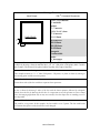
Adjusting the Windows 2000 Driver Bar Codes
Using the method just described, any Windows application can produce bar codes using the Fastmark drivers. Simply
selecting the font as a bar code font does this. The driver also provides ways to finely adjust the bar code printed. For
example, human readable text may be enabled or disabled. The X dimension may be adjusted. Depending on the bar
code type other parameters may be adjusted for example enabling or disabling a check digit.
Each bar code property may be accessed by selecting the driver then Advanced Options dialog box. Each bar code
type is listed. Click on the + symbol to expand the possible selections for a particular bar code. Then the settings for
that bar code may be adjusted and will be saved with the current document.
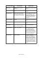
User's Guide 53
Windows XP Driver Installation
1. Go to the Printers and Faxes folder.
2. In the Printer Tasks window double click the Add a Printer icon. The Add Printer Wizard dialog should be
displayed. Click the Next button.
3. Select the Local printer option and click the Next button.
4. If the New Printer Detection dialog is displayed, click the Next button to install manually.
5. Select the desired printer port and click the Next button.
6. From the Manufacturers list dialog click the Have Disk button.
7. From the Install From Disk dialog browse to the location of the driver files. An installation file should be
displayed. The file has an .inf and the filename depends on the model being installed. Select this file and
click Open.
8. Click OK from the Install From Disk dialog.
9. The Add Printer Wizard should now display the available models for this driver. Select the model you wish
to install and click Next.
10. Select Replace existing driver. Click Next.
11. Choose whether to install the printer as the default printer. Click Next.
12. Select No to the print test page question since the test page does not fit within the printers page size and
click Next.
13. Click the Finish button on the Completing the Add Printer Wizard. If a Hardware Installation message is
displayed, click Continue Anyway. A printer icon should be added to the list of printers. If a message is
displayed indicating the installation could not be completed, you may need to change the security level for
installing drivers and repeat the installation process.
If you have set the printer as the default printer, the driver is now ready for use.
If you did not set the printer as the default printer, you can change the setting by right clicking on the printers' icon
and select 'Set as Default' from the dialog.
If you are replacing an existing driver, you may have to reboot your system in order to reload the new driver.
User's Guide 54
Selecting Printer Fonts
When the driver is installed, a custom True Type font is also installed called AMT Sans Serif which closely matches
the resident scalable font in the printer. This font may be printed in a variety of point sizes. Using this font increases
print speed and minimizes the data transmitted to the printer. Use of other True Type fonts are supported but are
printed as graphics. To use the printer resident font:
1) For each size font highlight the font using the mouse.
2) From your applications font selection list, select AMT Sans Serif font.
3) Using your applications font size ability, select the point size as needed to produce the size font desired.
Repeat for all text area's for which you will use the printer resident font.
User's Guide 55
Printing Bar Codes From Windows XP Applications
Using the Fastmark PALTM Windows driver, printing bar codes from any Windows application is possible. These bar
codes are printed using the internal bar code ability of the printer resulting in superior bar code quality. The following
steps indicate how to do this:
1) Ensure the Fastmark PALTM Driver is selected within this application.
2) Select the media size to be used for this label.
3) Position the text or numeric data at the approximate position it is to be printed at using whatever methods are
possible within the particular program you are using. You can use a text box if supported by your
application.
4) If your application supports text rotation, you can do this now. Some applications may require you to use a
"text box" to generate rotated text.
5) Highlight this text or numeric data as you normally would before changing the font.
6) Using the normal method of selecting fonts such as a pull down menu, select one of the bar code fonts
displayed such as FM Code 128A.
Note: The font will still be displayed as text or numeric data however when printed will appear as a barcode.
User's Guide 56
Adjusting the Windows XP Driver Bar Codes
Using the method just described, any Windows application can produce bar codes using the Fastmark drivers. Simply
selecting the font as a bar code font does this. The driver also provides ways to finely adjust the bar code printed. For
example, human readable text may be enabled or disabled. The X dimension may be adjusted. Depending on the bar
code type other parameters may be adjusted for example enabling or disabling a check digit.
Each bar code property may be accessed by selecting the driver then Advanced Options dialog box. Each bar code
type is listed. Click on the + symbol to expand the possible selections for a particular bar code. Then the settings for
that bar code may be adjusted and will be saved with the current document.
User's Guide 57
Windows NT/9x Driver Installation
1. Go to the Printers and Faxes folder.
2. Double click the Add Printer icon. The Add Printer Wizard dialog should be displayed. Click the Next button.
3. Select the Local printer option and click the Next button.
4. Select the desired printer port and click the Next button.
5. From the Manufacturers list dialog click the Have Disk button.
6. From the Install From Disk dialog browse to the location of the driver files and click OK.
7. From the Install from Disk dialog, select the displayed .inf file and click OK.
7. Click OK from the Install From Disk dialog.
8. The Add Printer Wizard should now display the available models for this driver. Select the model you wish to
install and click Next.
9. Select No to the print test page question since the test page does not fit within the printers page size and click
Next.
10. Click the Finish button on the Completing the Add Printer Wizard. A printer icon should be added to the list
of printers.
If you have set the printer as the default printer, the driver is now ready for use.
If you did not set the printer as the default printer, you can change the setting by right clicking on the printers' icon
and select 'Set as Default' from the dialog.
If you are replacing an existing driver, you may have to reboot your system in order to reload the new driver.
User's Guide 58
Selecting Printer Fonts
The driver has a resident font called AMT Sans Serif which is displayed in the application’s font list. This font may
be printed in a variety of point sizes. Using this font increases print speed and minimizes the data transmitted to the
printer. Use of True Type fonts are supported but are printed as graphics. To use the printer resident font:
1) For each size font highlight the font using the mouse.
2) From your applications font selection list, select AMT Sans Serif font.
3) Using your applications font size ability, select the point size as needed to produce the size font desired.
Repeat for all text area's for which you will use the printer resident font.
User's Guide 59
Printing Bar Codes From Windows NT/9x Applications
Using the Fastmark PALTM Windows driver, printing bar codes from any Windows application is possible. These bar
codes are printed using the internal bar code ability of the printer resulting in superior bar code quality. The following
steps indicate how to do this:
1) Ensure the Fastmark PALTM Driver is selected within this application.
2) Select the media size to be used for this label.
3) Position the text or numeric data at the approximate position it is to be printed at using whatever methods are
possible within the particular program you are using. You can use a text box if supported by your
application.
4) If your application supports text rotation, you can do this now. Some applications may require you to use a
"text box" to generate rotated text.
5) Highlight this text or numeric data as you normally would before changing the font.
6) Using the normal method of selecting fonts such as a pull down menu, select one of the bar code fonts
displayed such as FM Code 128A.
Note: The font will still be displayed as text or numeric data however when printed will appear as a barcode.
User's Guide 60
Adjusting the Windows NT/9x Driver Bar Codes
Using the method just described, any Windows application can produce bar codes using the Fastmark drivers. Simply
selecting the font as a bar code font does this. The driver also provides ways to finely adjust the bar code printed. For
example, human readable text may be enabled or disabled. The X dimension may be adjusted. Depending on the bar
code type other parameters may be adjusted for example enabling or disabling a check digit.
Each bar code property may be accessed by selecting the driver then Advanced Options dialog box. Each bar code
type is listed. Click on the + symbol to expand the possible selections for a particular bar code. Then the settings for
that bar code may be adjusted and will be saved with the current document.
User's Guide 61
Using the Windows Driver To Produce PALTM Print Command Examples
To use the Windows driver to produce a PALTM sample for use in host programming do the following:
1) Design the label as needed using suitable Windows application.
2) Where possible always use the printer resident font such as AMT Sans Serif.
3) Use bar code fonts for data fields to be printed as bar codes. Use the driver Advanced Properties dialog box
to select various options for the bar codes to be printed.
4) While working on the label format, print to the attached Fastmark printer as needed to finally adjust the
position of text, lines, boxes, graphics, and bar codes.
5) When the printed output closely matches the desired output, use the Print to File option of the driver and give
the output a descriptive name with a .txt extension. For example shipping.txt.
6) Edit this text file using any text editor for a sample PALTM Print and Program commands. This file may be
further adjusted referring to the PALTM Print and Program Reference Manual, or used as is. It may be
incorporated into a host program or just used as a reference.
User's Guide 62
TROUBLESHOOTING AND MAINTENANCE
The printer can detect the following errors. In each case the READY LED will blink at a steady rate to indicate there
is an error. If the error is not obvious (Media or Ribbon Out) use the Feature Management Mode (and FeatureMan
program) to determine the error. When the Feature Management Mode is enabled the FeatureMan program will
display the corresponding error message.
Printer Detected Errors
LCD ERROR MESSAGE
DESCRIPTION
RECOVERY
Error: Power Fail
The printer has detected
+24VDC has dropped below a
minimum acceptable level
causing the printer to back up
all settings to EEPROM.
Turn printer off, wait 5
seconds and turn back on.
Error: Media Out
The printer has detected a
media out condition while
printing or feeding media.
Open print head and replace
media. Close print head and
press the FEED key. If media
appears to be loaded, check
for proper routing, check
Media Sensing feature to
make sure it matches media
type used either gap or black
bar. Run the Media
Calibration test.
Error: Media Feed
A media feed error is
displayed when the printer is
unable to find the top of form
indication as configured either
gap, or black bar.
Open print head and verify
media is loaded correctly.
Check the feature Media
Sensing and verify it is set to
the type of media used either
gap, or black bar. Close print
head and press the FEED key.
Run the Media Calibration
test.
Error: Ribbon Out
Reported when the printer
detects the end of ribbon while
printing or feeding media after
the current label is complete.
Open the print head, remove
old ribbon cores, replace with
new ribbon ensuring the
routing is correct. Close print
head and press the FEED key.
If this is direct thermal
application, change Media
Type feature to Direct
Thermal.
User's Guide 63
Printer Detected Errors (Continued)
Error: Image System
Error reported by the imaging
sub-system indicating a
memory shortage or other
graphics problem.
Press the FEED key to
remove current print job.
Cycle power on the printer.
Verify communications
settings are correct. Re-send
print job.
Error: Data Format
The printer has detected a data
format or parity error on the
serial port. This could be
caused by improper settings
between host and printer or a
glitch in data transmission
such as a PC being powered
up.
Press the FEED key to clear
the error and print buffer.
Resend the print job. If the
error occurs again verify baud
rate, data bits, and parity
settings match host and cable
pin out are correct.
Error: Data Overrun
This error is unlikely to occur
and would indicate data is
being transmitted to the printer
faster than it can be processed.
If this error does occur it
might indicate a faulty parallel
cable or other communication
problem.
Press the FEED key then
cycle power on the printer. If
the error occurs again verify
all communication features
are set to match host and
quality interface cables
correctly pinned out are used.
Error: Buffer Overflow
This error indicates the
printers incoming print buffer
(FIFO) has overflowed. The
most common cause of this
error is improper handshaking
between the printer and host
due to improper settings or
improper cable.
Press the FEED key and resend the print job. If the error
occurs again verify all
communication features are
set to match host and quality
interface cables correctly
pinned out are used.
Software Locked
This error is reported when
PALTM Print and Program
firmware is loaded into a
printer after another type of
firmware was previously
installed. Since PALTM Print
and Program firmware is
Copyrighted, a special code is
needed to enable it.
Call your sales representative
for information on how to
correct this error.
User's Guide 64
User Detected Errors
The following issues may be detected by the user but are not reported by the printer.
Vertical streaks in the print
This could indicate a dirty or faulty print head. Clean the print head first. Verify the media does not have excessive
paper fibers or dust. Verify there are no nicks or burrs anywhere in the paper path such as a scratched rail. If no other
source of streaks can be found replace the print head.
Vertical gaps in the print
This could indicate a dirty or faulty print head. First clean the print head. Verify the ribbon is not wrinkling. Verify
darkness feature is set high enough. Manually add force to the print head bracket in the area of the streaks. If the
streaks go away the print head itself is not the cause.
Poor print out quality
#
Verify type of media and ribbon (if used) are compatible.
#
Verify ribbon is not being used with direct thermal media.
#
Lower print speed and adjust print darkness.
#
Verify print head is clean.
#
Verify platen roller is clean.
#
Verify media and ribbon are both loaded exactly as described in media and ribbon loading sections.
#
Replace print head if print out is streaked or missing and all of above does not resolve.
User's Guide 65
Preventive Maintenance
Before performing any Preventive Maintenance be sure to turn off the printer's power and unplug the power cable.
Cleaning the Thermal Print Head (TPH)
It is recommended at a minimum that the Print Head should be cleaned:
•
Each time a Ribbon is changed.
•
Each time a new roll of media is installed.
1.
Turn off the printer, open the top cover, and if installed remove the ribbon.
2.
Lift the print head module to the vertical position.
3.
Rub the print head with a piece of cotton, which has been moistened with Isopropyl Alcohol, or use a thermal
head-cleaning pen.
4.
Check for any traces of discoloration or adhesive on the cotton after cleaning.
5.
Repeat if necessary until the cotton is clean, after it is passed over the print head.
Print Head
Figure 20 – Print Head Location
Note: The print head should be cleaned at least every time the ribbon is replaced and more often depending on
actual usage and conditions.
User's Guide 66
Cleaning the Platen Roller
It is recommended that the platen roller should be cleaned when:
•
Excessive dusty condition exists.
•
Following a media jam where the adhesive comes in contact with it.
1.
Turn off the printer and open the top cover.
2.
Lift the print head module to the vertical position.
3.
Rub the full length of the platen available with a piece of cotton, which has been moistened with Isopropyl
Alcohol.
4.
Manually rotate the platen and repeat step 3 until the entire platen has been cleaned.
Platen Roller
Figure 21 – Platen Roller
Note: The roller should be cleaned whenever it has been in contact with foreign materials such as dust or
adhesives.
User's Guide 67
Cleaning the Paper Compartment
It is recommended that the Paper Compartment be cleaned regularly if exposed to a dust environment. This will keep
dirt and dust from contaminating or damaging your printer (Print Head and Platen).
1.
Turn off the printer and open the top cover.
2.
Remove paper dust by blowing using compressed air or vacuuming.
3.
Clean the paper compartment with cotton, which has been moistened with mild detergent.
Cleaning the paper sensor
It is recommended that the Paper Sensor be cleaned regularly if exposed to a dusty environment. This will prevent
false paper OUT or paper IN conditions.
1.
Turn off the printer and open the top cover.
2.
Remove paper dust by blowing using compressed air or vacuuming.
3.
Clean the two Paper Sensor LED's with cotton stick, which has been moistened with Isopropyl Alcohol.
Paper Compartment
Paper Sensor
Figure 22 – Paper Compartment and Paper Sensor
User's Guide 68
Appendix A: GENERAL SPECIFICATIONS
Note: The FM402TT does not support the PALTM Print and Program Language but is included here for reference
only.
Specification
Print method
Resolution
Maximum print
width
Maximum print
length
Maximum print
speed
Onboard RAM
Media type
FM402TT
FM412TT
FM403TT
Direct thermal and thermal transfer
203 DPI
203 DPI
300 DPI
(8 dots/mm)
(8 dots/mm)
(12 dots/mm)
4.2 in. (107 mm)
4.10 in. (104 mm)
43 in. (1090 mm)
**
80 in. (2032 mm)
54 in. (1371 mm)
**
3 inches (76.2 mm) per second
2 inches (50.8 mm)
per second
512 K bytes
2 M bytes
2 M bytes
Direct thermal: Paper, vinyl, visible light and infrared
scannable label, tag stock, butt cut or die cut, with various
adhesives.II.
hThermal transfer: Paper or vinyl labels and tags, butt cut or
die cut, with various adhesives.
Maximum label
4 in.(102mm) outside diameter, 1 in.(25.4mm) inside
roll diameter
diameter
Label indexing
Black stripe and gap
Ribbon types
Wax, Wax/resin and Resin
Ribbon size
OD 1.45 in. (37 mm); ID 0.5 in. (12.7mm)
Interface
RS-232 serial and Centronics parallel ports, with auto polling
Dimension
Weight
Electrical
W7.3 in. x D10.9 in. x H6.0 in.
(W186 mm x D278 mm x H153mm)
1.9 kg (4.1 lbs.)
FCC class B
FCC class A
CE, UL and CUL approved. Input 19 VAC or 24 VDC
(min. 2.5 A), 50/60 Hz
Operating
temperature
Storage
temperature
Humidity
Windows driver
Printer emulation
Rotation
40° to 140°F (5° to 38°C)
-40° to 140°F (-40° to 60°C)
15 to 85% RH
Win, 95, 98, 2000, XP and NT
PPLA, PPLB
o
o
PAL, Text, Display, Hex
o
o
0 , 90 , 180 and 270 , 4 direction rotations
User's Guide 69
Appendix B: INTERFACE SPECIFICATIONS
This appendix presents the serial and parallel interface specifications. These specifications include pin assignments,
protocols and detailed information about how to properly interface your printer with your host or terminal.
Serial Interface
Pin Configuration
The RS-232 serial interface uses a female, DB-9 conncetor.
Pin
1
2
3
4
5
6
7
8
9
Direction
Tied to in 6
In
Out
Tied to pin 1
Out
In
Out
Definition
Not used
Receive Data (RxData)
Transmit Data (TxData)
No connection
Logic Ground
Not used
Request to Send (RTS)
Clear to Send (CTS)
+5V
Note: Pin 9 is reserved for Keyboard Device Unit (KDU) only, do not connect this pin if you are using a general
host like a PC.
Connection With Host
Host 25S
Printer 9P
Host 9S
(PC or compatible)
DTR 20
DSR 6
TX 2
RX 3
CTS 5
RTS 4
GND 7
……… 1 DSR
……… 6 DTR
……… 2 RX
……… 3 TX
……… 7 RTS
……… 8 CTR
……… 5 GND
Printer 9P
(PC or compatible)
DTR 4
DSR 6
TX 3
RX 2
CTS 8
RTS 7
GND 5
……… 1 DSR
……… 6 DTR
……… 2 RX
……… 3 TX
……… 7 RTS
……… 8 CTS
……… 5 GND
Three Wire Connection
This method is the simplest method of connecting the printer to a host or terminal. This method requires Software
Protocol Handshaking (XON/XOFF flow control).
Host 25S
Printer 9P
Host 9S
(PC or compatible)
(PC or compatible)
TX 2
RX 3
GND 7
pin 4
pin 5
pin 6
pin 20
TX 3 ………..
RX 2 ………..
GND 5 ………..
pin 4
Pin 6
Pin 7
Pin 8
……….. 2 RX
……….. 3 TX
……….. 5 GND
Printer 9P
2 RX
3 TX
5 GND
Serial port settings
Baud Rate, Parity, Data Bits, and Handshaking may be configured using the Feature Management mode.
User's Guide 70
Parallel (Centronics) Interface
The parallel port uses a standard 36-pin Centronics connector.
Pin
Direction
Definition
Pin
Direction
Definition
1
In
2
In
/STROBE
13
Out
SELECT
Data 1
14,15
3
In
Data 2
16
-
Ground
4
In
Data 3
17
-
Ground
5
In
Data 4
18
6
In
Data 5
19 to 30 -
Ground
7
In
Data 6
31
NC
8
In
Data 7
32
9
In
Data 8
33 to 36 -
10
Out
/ACK
11
Out
BUSY
12
Out
PE
NC
NC
Out
/Fault
NC
Auto Interface Select
The setup feature Interface Select controls the operation of interface arbitration. One of 3 settings is possible:
Parallel Only: With this setting the serial interface is ignored.
Serial Only: With this setting the parallel interface is ignored.
Auto Select: With this setting, the printer automatically arbitrates between the parallel and serial interfaces. The first
interface to go active maintains active status while the other interface is held busy. After a time out period, the other
interface is placed in a ready state.
User's Guide 71
Appendix C: ASCII TABLE
The following table may be used to determine HEX values of ASCII characters. For example the character A is hex
41 commonly shown as 0x41H.
0
0
NUL
1
SOH
2
STX
3
1
XON
XOFF
4
5
NAK
2
3
4
5
6
7
0
@
P
`
P
!
1
A
Q
a
Q
“
2
B
R
b
R
#
3
C
S
c
S
$
4
D
T
d
T
%
5
E
U
e
U
6
ACK
&
6
F
V
f
V
7
BEL
‘
7
G
W
g
W
8
BS
(
8
H
X
h
X
)
9
I
Y
i
Y
*
:
J
Z
j
Z
+
;
K
[
k
{
9
A
LF
B
ESC
C
FF
,
<
L
\
l
|
D
CR
-
=
M
]
m
}
E
SO
RS
.
>
N
^
n
~
F
SI
US
/
?
O
_
o
DEL
User's Guide 72
Appendix D: SELF TEST PRINT SAMPLE
User's Guide 73
Appendix E: HIDDEN SETUP FEATURES
To access the hidden list of features, select the Firmware Rev. feature then click the Enter button twice. The hidden
feature list is now enabled and may be selected by clicking the Display Down button.
Hidden Setup Feature and Value List
FEATURE NAME
VALUE RANGE
DESCRIPTION
Ripple Pattern
N/A
Click the Enter button to
initiate a rolling ASCII ripple
pattern.
Factory Defaults
N/A
Clicking the Enter button
resets all keypad features to
factory defaults. If the RTC
clock is installed, these
features are not reset. The
Label Count Feature can not
be reset. Caution: This
feature could cause a loss of
communication with host if
interface features have been
modified.
PAL Boot Drive
[A:,B:,C:, Auto Detect]
This feature selects the boot
drive. During power up the
system will scan the boot
drive for a PAL program to
run. If Auto Detect is selected
the system will scan all
drives in succession, starting
with A:, searching for the first
PAL program to run.
N/A
Clicking the Enter button
causes main firmware control
to be halted and boot load
firmware to be loaded. This
mode has a distinct setup
mode feature list allowing
serial port parameters to be
adjusted for the firmware
download. See Appendix F
on firmware updates for more
information.
F/W Update Mode
User's Guide 74
Hidden Setup Feature and Value List (Continued)
Max Media Length
Keypad Lockout
Label Count
[12-80] inches
This feature sets the
maximum length media that
the printer will recognize. In
normal setup mode, this
value sets the upper limit on
the Media Length feature to
avoid excessive menu
scrolling. This also controls
how long of a label the
printer will look for when
performing a label
calibration. Increase this
value if media over 12 inches
long is used.
[Enabled, Disabled]
When Keypad Lockout is
Enabled, the value of
features may be viewed but
not changed. Also, any
feature value which may be
changed from downline using
a PALTM operator is also
locked out from change.
This feature may be used to
keep users from modifying
features or to override host
changes if needed.
N/A
This feature displays the
number of labels printed
since the printer was
manufactured. The total
label length issued by the
printer will be dependant on
the label length used. For
example if 4 inch label stock
is used and the Label Count
feature indicates 100, then
400 inches of media have
been printed.
User's Guide 75
Appendix F: UPDATING PRINTER FIRMWARE
Occasionally there may be a need to update printer firmware either to enhance capabilities or correct issues. Updating
firmware via the parallel interface is possible only after activating the printers boot mode firmware. Use the
following procedure to activate the boot mode firmware:
1) Enable the Feature Management mode. (Refer to the section Feature Management Mode section for
instructions.)
2) Enable the Hidden Setup Features. (Refer to Appendix E for instructions.)
3) Scroll to the hidden F/W Update Mode feature.
4) Click the Enter button to activate boot mode firmware
After the boot mode firmware is activated, the FeatureMan program will display the following.
Off line:
F/W Update Mode
The only possible actions at this point are to enter boot setup mode or cycle power to exit this mode. This
setup mode works like the normal printer setup mode except the feature list is limited to specific features used
during firmware updates. Click the Display Up/Down buttons to enter the boot setup mode. (Refer to the
Boot Mode Feature and Value List for a description of the features.)
5) Scroll to the Download New F/W feature.
When the Download New F/W feature is selected the FeatureMan program will open up a new ‘file
download’ section called FlashWiz Lite.
6) Click the Enter (or CANCEL) button to activate the Download New F/W mode.
After the Download New F/W mode is activated, the FeatureMan program will display the following.
Download New F/W
Waiting For Data
CANCEL to Stop
User's Guide 76
7) In the FlashWiz Lite section, select the appropriate LPT port to be used for the download.
8) Click the File button to select the appropriate download file.
9) Click the Send button to start the download.
10) After the download is complete follow the instructions on the display of the FeatureMan program to reset all
printer features.
At this point you can either continue operating the printer in the Feature Management Mode or you can exit.
To exit the Feature Management Mode power the print off, wait 5 seconds, then power the printer on.
Refer to the section Calibrating Media Sensors to recalibrate the printer.
User's Guide 77
Boot Mode Feature and Value List
The Boot Mode has several programmable features that are used during firmware updates. Click the Display
Up/Down buttons to access the Boot mode features.
FEATURE NAME
Download New F/W
VALUE RANGE
DESCRIPTION
N/A
Click the Enter button to start
download mode. The display
will change to:
Download New F/W
Waiting For Data /
<CANCEL to Stop>
The printer will wait on a
firmware update file on the
Parallel ports. The FlashWiz
Lite section of the FeatureMan program is used to
download firmware files.
Reboot System
N/A
To exit boot mode and return
to normal PALTM firmware
mode, click the Enter button.
After a firmware update is
complete, this feature is
automatically selected and
allows the printer to be
rebooted with the newly
loaded firmware.
Interface Select
Identical to feature in
standard setup mode.
COM1: Baud Rate
Defaults to 57K baud when in
boot mode. Change to
match host if needed.
COM1: Parity
Change to match host if
needed.
COM1: Data Bits
Change to match host if
needed.
COM1: Handshake
Change to match host if
needed.
Firmware Rev.
Displays revision of boot
code currently loaded. The
boot code can only be
updated by changing Flash
chips located on main board.
User's Guide 78