1
System Hardware Structure
The hardware aspect of the Remote Audiovisual Answering System ("The system") consists of three sets of
hardware components that are linked to the PC to make the data processing possible. These three sets of hardware
components are: 1) Camera, Receiver, and TV card, 2) Doorbell/Digital transmitter & digital receiver, and 3)
Analog transmitter & Receiver/Speaker.
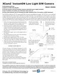
The first set is comprised of an Xcam2 wireless camera with a built in microphone that sends a video and
audio signal to the VR31A wireless receiver. The system also makes use of a programmable TV card that is installed
into a PCI slot. The Xcam2 camera sends an analog signal to the VR31A receiver. Since a PC deals only with digital
information, the TV card serves as the medium that establishes the communication link between the data being fed
by the camera to the receiver and the PC. This link is accomplished by connecting the VR31A receiver to the TV
card. The TV card then converts the analog signal to a digital signal. Since the camera is continually transmitting a
signal to the receiver, this implies that the TV card will also be continually digitizing the analog signal. However, at
this point the digitized information is not being recorded, but it is available in a format that a person would be able
to manipulate through programming.
The second set is comprised of a doorbell switch that is interfaced with a digital transmitter (refer to
“Digital Transmitting System” schematic). The computer locates the complementary digital receiver, since it needs
to be directly interfaced with the serial port to detect a visitor’s presence (refer to “Digital Receiving System”
schematic). To make up for the interference of other devices transmitting at the same frequency, the circuit at the
transmitter end is constantly sending a high logic. This way, if some other device sends a high logic at the same
operating frequency (315 MHz), the receiver circuit senses no change. However, when the visitor presses the
doorbell the transmitter is temporarily shut down, and the receiver circuit senses a low logic.
The receiver circuit consists of a digital transmitter connected to a 555 timer and a PNP transistor. This
circuit expects a sequence of high logic levels within a certain period. Whenever a pulse is missing within this
period, the output of this 555 timer goes low. The output of the above mentioned timer serves as the trigger input of
a mono-stable timer. When the trigger input of this mono-stable timer goes low, it sends a long pulse through the
LT1131 ACNW Rs-232 logic converter. The reason for this is so that the voltage at the serial port has enough time
to stabilize to it’s appropriate level, otherwise the change would be so quick that the computer will not detect the
change in voltage level, thus missing the fact that there might be a visitor at the front door.
The third set consists of a set of analog transmitter and receiver/speaker system. As soon as the computer
“realizes” that there is a visitor at the door, it plays an audio message through the sound card, telling the user to
leave a brief message since there is no one at home. For this, we use a dual 1/8” sound card cable. We connect one
end to the sound card, and the other end we connect it to the 1/8” audio jack at the analog transmitter circuit (refer to
the “Audio Transmitting System” schematic). The complementary audio receiver with speaker is mounted by the
front door so that the visitor may hear the notification that there is no one at home and that he/she needs to leave a
message (refer to the “Audio Receiving System” schematic).
Interfacing the Hardware Components
In order build this project you would need to buy all the necessary components listed on the project’s Parts
List document. You will need to build the Digital Transmitting System and Audio Receiving System circuits. Each
of these circuits should be build on a 550-pin breadboard and install them by the frame door along with the XCam2
video camera.
You will also need to build the complementary Digital Receiving System and Audio Transmitting System
circuits. Each of these circuits should be built on a 550-pin breadboard and interface it to the computer as illustrated
on each of the respective diagrams.
Since there are different brands of TV cards, you will need to refer to the TV card’s user’s manual for
installation. Once you’ve installed the TV card, you will need to connect the coaxial cable, supplied with the
VR31A A/V receiver, to the coaxial A/V Plug-ins of the VR31A A/V receiver and TV card.
For a better perception of the system functionality, refer to the Interconnection/ Interactivity document.
System Software Structure
The software phase of the project will be comprised of a user interface, and a mail client program.
In the user interface portion of the programming phase, before the program is set to record, the user will
need to provide the system with appropriate E-mail addresses (recipient and sender), domain name server, the port
that is being used to detect the presence of a visitor, and the audio messages that will be played when the visitor
presses the bell. This information will be saved to the registry, which will be used to initialize the application next
time it is loaded.
When a visitor arrives to your residence and press the doorbell, the program will play an audio file that
prompts the user to leave a message. As soon as this audio files stops playing, the program will start recording a
video message of the current visitor.
After recording the message, the program will obtain the computer system’s date and time to name the
recorded video message. The program then saves this file to an "outgoing messages" folder and then attempts to
establish a connection to the SMTP server to send the video message via E-mail.
Upon connection failure, the program will keep the message(s) in the outgoing messages folder. The
program will attempt to connect to the server after 30 minutes from the time it last attempted to establish a
connection. Then, the program waits until either the doorbell is pressed, or until the 30 minutes has elapsed.
However, in the first case, we know that a visitor has arrived and the program will follow the initial program flow as
when it is first actuated. In the second case, the program will once again attempt to establish a connection to the
SMTP server and the cycle repeats if it is unsuccessful.
However, if the program was initially successful in establishing a connection to the server, the program will
call the mail client program to send the video message file as an attachment to the user’s specified E-mail address.
Then, it will move the file from the “outgoing messages” folder to the "sent messages" folder. If there are pending
messages it will open a new session and send each video message in a single E-mail. During this process if a new
visitor arrives the program will notify the visitor that the system is currently busy. When the current process
finishes, then the program will prompt the visitor to leave his/her message. At this point the program will begin a
new process. Once the program finishes sending all the pending messages it will simply wait for a new visitor to
arrive.
Interfacing the Hardware Components
In order build this project you would need to buy all the necessary components listed on the project’s Parts
List document. You will need to build the Digital Transmitting System and Audio Receiving System circuits. Each
of these circuits should be build on a 550-pin breadboard and install them by the frame door along with the XCam2
video camera.
You will also need to build the complementary Digital Receiving System and Audio Transmitting System
circuits. Each of these circuits should be built on a 550-pin breadboard and interface it to the computer as illustrated
on each of the respective diagrams.
Since there are different brands of TV cards, you will need to refer to the TV card’s user’s manual for
installation. Once you’ve installed the TV card, you will need to connect the coaxial cable, supplied with the
VR31A A/V receiver, to the coaxial A/V Plug-ins of the VR31A A/V receiver and TV card.
For a better perception of the system functionality, refer to the Interconnection/ Interactivity schematic
documentation.