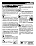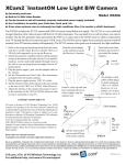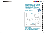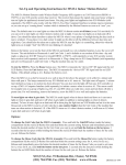
1
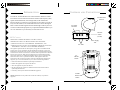
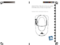
Audio/Video Receiver for use with
X10 Wireless Camera Systems
MODEL VR31A OWNER'S MANUAL
INTRODUCTION
The VR31A Audio/Video Receiver works with X10's Wireless Cameras.
The Camera converts video and sound into wireless radio frequency (RF)
signals and transmits them (even through walls) to the Audio/Video
Receiver which you connect to a TV anywhere in your home (up to 100 ft.
away from the Camera). The Audio/Video Receiver converts the signals
back to video and audio signals which are fed through a cable to your TV's
COAX or Audio/Video input jacks. If you purchase additional VR31As you
can view and listen to your camera(s) on more than one TV.
CONTROLS
AND
CONNECTIONS
2.4 GHz Video
Antenna
TV Output
Connector
ON-OFF
Switch
(on side)
TO TV
D C 12 V
V ID EO O U T A U D IO O U T
FCC CAUTION
THIS DEVICE COMPLIES WITH PART 15 OF THE FCC RULES.
Power Supply
Jack
OPERATION IS SUBJECT TO THE FOLLOWING TWO CONDITIONS:
(1)THIS DEVICE MAY NOT CAUSE HARMFUL INTERFERENCE, AND
(2)THIS DEVICE MUST ACCEPT ANY INTERFERENCE RECEIVED, INCLUDING
INTERFERENCE THAT MAY CAUSE UNDESIRED OPERATION.
This equipment generates and uses radio frequency energy, and if not installed and used
properly, that is, in strict accordance with the manufacturers instructions, it may cause
interference to radio and television reception. It has been type tested and found to comply
with the limits for remote control devices in accordance with the specifications in Sub-Parts
B and C of Part 15 of FCC Rules, which are designed to provide reasonable protection
against such interference in a residential installation. However, there is no guarantee that
interference will not occur in a particular installation. If this equipment does cause
interference to radio or television reception, which can be determined by unplugging the
equipment, try to correct the interference by one or more of the following measures.
A/V Jacks
TV
C H A N N EL
TV
Channel
Switch
3 4
• Reorient the antenna of the radio/TV experiencing the interference.
• Relocate the equipment with respect to the radio/TV.
• Move the equipment away from the radio/TV.
• Plug the equipment into an outlet on a different electrical circuit from the radio/TV
experiencing the interference.
CH A N N EL
A BC D
• If necessary, consult your local Dealer for additional suggestions.
NOTE: Modifications to this product will void the user's authority to operate this
equipment.
2
2.4 GHz
Channel
Switch
3
C ONNECTING UP
IF YOUR TV IS ALREADY HOOKED UP TO A
DBS RECEIVER OR OTHER A/V DEVICE
1. Connect a set of Audio/Video cables to
the A/V OUT jacks on the Audio/Video
Receiver. Connect the other end to
your TV (use Yellow for video, and
either L or R channel for audio).
V ID E O
A U D IO
TO TV
TV
2. Plug the Audio/Video Receiver's Power
Supply jack (the power supply with NO
code wheels) into the Audio/Video
Receiver and plug the power supply
into a 120 volt wall outlet.
V ID EO
If a DBS Receiver or other A/V
component is connected to the TV using
A/V cables, you can connect the Audio/
Video Receiver to the free LINE IN jacks
on the component. If there are no LINE
IN jacks, you will need to use a TV
antenna splitter as described earlier.
A U D IO
3. Turn the Audio/Video Receiver's power
switch (on side of unit) on.
4. Set the channel switch to the same letter as you set on the camera, A,
B, C, or D.
5. Position the Audio/Video Receiver in a convenient location such as on
top of the TV and orient the antenna so that the flat side points in the
direction where you set up the Camera.
IF YOUR TV DOES NOT HAVE A/V CONNECTORS
You can use the supplied coaxial cable to connect the TV OUT socket on
the Audio/Video Receiver to the Antenna input on your TV.
If you already have an
antenna connected to
your TV, you will need to
use a TV antenna
splitter. Set your TV and
the TV Channel switch
on the Audio/Video
Receiver (on bottom) to
the same channel (3 or
4).
TO TV
V ID E O
FINE TUNING YOUR SYSTEM
The system usually works best with the "pip" on the Camera's antenna
facing the flat side of the Receiver's antenna (see diagram below).
Sometimes, however, reflections and other effects in the home may affect
the signal so that some adjustment of either the Camera or Receiver
antenna may be necessary to get the best signal. If you have more than one
Camera, sometimes pointing the Receiver's antenna up towards the ceiling
works best.
pip
A U D IO
TO TV
ANTENNA
TV
1
CAMERA/SENDER
SOLD SEPARATELY
2
VIDEO RECEIVER
UHF/VHF
ANTENNA
4
5
TROUBLESHOOTING
If you do not see a picture on your TV:
In most cases, relocating the Camera or Receiver a few feet is enough to
avoid the source of interference.
Check that the Receiver and the Camera are on the same letter channel (A,
B, C, or D). On the Receiver the switch is on the bottom. On the Camera the
switch is located under the rubber plug on the base of the unit. Make sure you
replace the plug afterwards if you intend to use the camera outdoors.
Try unplugging/turning off any electromagnetic interference producing devices,
such as a microwave oven, baby monitor, computer, wireless LAN, wireless
speakers, cordless phone, cell phone, etc.
There is a power light on the front of the Receiver. Check that the power
switch on the side of the Receiver is ON.
Check that the Camera is turned on. For single camera systems the power
supply for the Camera will normally be on (it powers up on). For Multi-Camera
systems you need to purchase a TM751 Transceiver for the remote control to
be able to turn Cameras on. When you turn any one on, in a group of 4 on, the
others in the group turn off. Groups must be 1-4, 5-8, 9-12, or 13-16. Check
that all camera power supplies are set to the same Housecode as the Transceiver
and remote control.
Verify that your connections to the TV are correct. If you are using the RCA
jacks, make sure you are using the appropriate input mode for your TV, try
pressing the A-B button or Video button on your TV's remote control to change
the input mode (consult your TV's owner's manual, if necessary). If you are
using the Coax cable, verify that the Receiver and the TV are on the same
channel (3 or 4).
If you connected the Receiver to a VCR and then connected the VCR to your
TV, you might need to turn the VCR OFF to see the Camera's picture on your
TV. Or you might need to turn the VCR on, AND set it to record the picture
from the Camera, in order to see the picture on your TV. Or you might need to
press the A-B button on your VCR's remote control. Consult your VCR's
owner's manual from more information.
If you get a picture but the quality is poor:
Try different positions for the antennas on the Camera and Receiver. Normally
they should point at each other. Sometimes, due to reflections, you might get a
better picture with the Receiver's antenna pointing to the ceiling.
Other 2.4 GHz devices can distort the Camera's picture and/or cause buzzing
in the audio. If you are experiencing interference between X10 Cameras and
some other equipment that uses 2.4 GHz, check the other device's owner's
manual for the frequencies of each channel that it uses. X10 cameras use the
following frequencies: Channel A: 2.411 GHz, Chan B: 2.434 GHz, Chan C:
2.453 GHz, Chan D: 2.473 GHz. We recommend using a frequency on the
other device that is farthest from channel A or D, depending on which side of
the band the other device is transmitting. Otherwise you will need to discontinue
use of the device while using the Cameras.
If the camera is out of focus:
The camera is shipped preset to be in focus for normal use, but if you want to
change the focus you can remove the clear plastic cover and rotate the inner
portion of the lens. It might be a bit tight. Try turning it counterclockwise first.
If you turn it clockwise do not force or over tighten it. For outdoor use, replace
the clear plastic cover to keep the rain out.
If you are having difficulty turning the Camera on/off remotely:
Plug the Transceiver (the white module with an antenna) into a different outlet.
Note a Transceiver (sold separately) is REQUIRED for Multi-Camera systems.
It is not required if you only have one camera as the camera's power supply
powers up on when you plug it in.
If the Remote Control (sold separately) doesn't do anything.
Check that the red light on the remote comes on when you press any button.
Check that you have the batteries installed correctly, replace if necessary with
4 AAA alkaline batteries. Try the Transceiver in different outlets (see above).
For more help with setup please visit www.x10.com/support
Take a look at what the video signal is passing through or near to get to the
Receiver. Metal objects and electromagnetic fields can distort the signal. Try
to keep the Receiver as far away from other devices as the cables allow.
6
7
12 MONTH LIMITED WARRANTY
X10.COM A DIV. OF X10 WIRELESS TECHNOLOGY, INC. (X10) WARRANTS ITS
PRODUCTS TO BE FREE FROM DEFECTIVE MATERIAL AND WORKMANSHIP
FOR A PERIOD OF ONE (1) YEAR FROM THE ORIGINAL DATE OF PURCHASE
AT RETAIL. X10 AGREES TO REPAIR OR REPLACE, AT ITS SOLE DISCRETION,
A DEFECTIVE X10 PRODUCT IF RETURNED TO X10 WITHIN THE WARRANTY
PERIOD AND WITH PROOF OF PURCHASE.
IF SERVICE IS REQUIRED UNDER THIS WARRANTY:
1. CALL 1-800-675-3044, OR VISIT WWW.X10.COM, OR E-MAIL
[email protected] TO OBTAIN A RETURN MERCHANDISE
AUTHORIZATION (RMA) NUMBER.
2. RETURN THE DEFECTIVE UNIT POSTAGE PREPAID TO THE ADDRESS
BELOW
3. ENCLOSE A CHECK FOR $4.00 TO COVER HANDLING AND RETURN
POSTAGE.
4. ENCLOSE A DATED PROOF OF PURCHASE.
5. X10 IS NOT RESPONSIBLE FOR SHIPPING DAMAGE. UNITS TO BE
RETURNED SHOULD BE PACKED CAREFULLY.
THIS WARRANTY DOES NOT EXTEND TO ANY X10 PRODUCTS WHICH
HAVE BEEN SUBJECT TO MISUSE, NEGLECT, ACCIDENT, INCORRECT WIRING
OR TO USE IN VIOLATION OF OPERATING INSTRUCTIONS FURNISHED BY
US, NOR EXTEND TO ANY UNITS ALTERED OR REPAIRED FOR WARRANTY
DEFECT BY ANYONE OTHER THAN X10. THIS WARRANTY DOES NOT
COVER ANY INCIDENTAL OR CONSEQUENTIAL DAMAGES AND IS IN LIEU
OF ALL OTHER WARRANTIES EXPRESSED OR IMPLIED AND NO
REPRESENTATIVE OR PERSON IS AUTHORIZED TO ASSUME FOR US ANY
OTHER LIABILITY IN CONNECTION WITH THE SALE OF OUR PRODUCTS.
SOME STATES DO NOT ALLOW LIMITATIONS ON HOW LONG AN IMPLIED
WARRANTY LASTS, AND/OR THE EXCLUSION OR LIMITATION OF
INCIDENTAL OR CONSEQUENTIAL DAMAGES SO THE ABOVE LIMITATIONS
AND EXCLUSIONS MAY NOT APPLY TO THE ORIGINAL CUSTOMER. THIS
WARRANTY GIVES YOU SPECIFIC RIGHTS AND YOU MAY ALSO HAVE
OTHER RIGHTS WHICH VARY FROM STATE TO STATE.
X10.com, a div. of X10 Wireless Technology, Inc.
Returns Depot, 3824 North 5th St.,
Suite C, North Las Vegas, NV 89032
Web Site: www.x10.com
VR31A-09/01