1
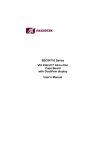
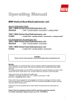
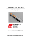
Flat Bed Electrophoresis Chamber MULTI
for IsoElectric Focussing Applications using IEF Gels or IPG Strips, and for
Flat Bed Gel Electrophoresis in general
CP51.1
Warning: Like all apparatus run by electricity these units are capable of delivering potentially lethal
voltage when connected to a power supply. They should be operated only by qualified technically
trained personnel.
The horizontal electrophoresis units from ROTH are designed for long term laboratory use and to
obtain reproducible results. Please spend a few moments reading the instruction manual thoroughly.
DO NOT attempt to remove the outer casing or make repairs to our electrical range of products,
should any unit fail.
These units comply with the statutory CE safety rules: 73/23/EEC: Low voltage directive: IEC 10101:1990 plus amendment 1:1992, EN 61010-1:1993/BS, EN 61010-1:1993
Please verify that you received the unit completely and without any damage. Any faults or losses have
to be reported to ROTH immediately. ROTH can not accept responsibility for goods that were sent
back without informing them.
Please take a look at the packing list and check whether all components and accessories are present
Please retain all packaging material until the warranty period has expired.
SPECIFICATIONS:
Technical specifications:
Unit dimensions (WxDxH) incl. cooling coil
Inner tank dimensions (WxDxH)
Dimensions of electrode frame, cooling plate and glas plate (WxL)
Maximum gel size
Recommended temperature for gel-IEF
Recommended temperature for IEF using IPG strips
Recommended temperature for flat bed gel electrophoresis
Power output connectors (Ø)
Snap-lock connectors for cooling coil
Quick-fit tubing
1
46 x 41 x 11.5 (cm)
37 x 31 x 8.5 (cm)
27 x 27 (cm)
250 x 250 (mm) or
30 3 mm IPG strips
20 °C
4 °C
4 °C
2 mm shrouded
Inner Ø: 10 mm
Outer Ø: 12 mm
Inner Ø: 10 mm
Outer Ø: 12 mm
Recommended running conditions for IEF:
Running conditions for
Step
IEF gels with length
Voltage (V)
10-15 cm
Time (mins)
Volt-hour
Running conditions for
Step
IEF with IPG strips
Voltage (V)
of 5-10 cm length
Time (mins)
Volt-hour
Running conditions for
Step
IEF with IPG strips
Voltage (V)
of 15-20 cm length
Time (mins)
Volt-hour
1
300
20
100
1
150
0.5
75
1
300
1
300
2
600
20
200
2
300
0.5
150
2
600
1
600
3
1.000
30
500
3
600
0.5
300
3
1.500
1
1.500
4
1.200
30
600
4
1.500
0.5
750
4
3.000
12.5
37.500
5
1.500
30
750
5
3.000
2.5
7.500
5 (end)
330
<20
-
6 (end)
2.000
60
2.000
6 (end)
330
<20
-
Technical features:
• Rugged acrylic construction.
• Ceramic cooling plate, connectable to chiller or water-tap.
• Glass electrode frame for optimal cooling efficiency.
• All acrylic joints chemically bonded.
• Doubly insulated cables, rated safe up to 10.000 volts.
• Gold plated electrical connectors, corrosion-free and rated safe up to 10.000 volts.
• Recessed power connectors, integral with the safety lid.
• 0.2 mm diameter platinum electrodes, 99.99 % pure.
• Glass electrode weight for optimal contact situation.
• Silicone rubber dovetail seal provides leak-free sealing and are easy to clean and or replace.
• User friendly clamping system.
• Wide range of accessories.
Environmental Conditions:
• This apparatus is intended for indoor use only.
• This apparatus can be operated safely at an altitude of 2.000 m.
• The normal operating temperature range is between 4 °C and 65 °C.
• Maximum relative humidity 80 % for temperatures up to 31 °C decreasing linearly to 50 % relative
humidity at 40 °C.
• The apparatus is rated POLLUTION DEGREE 2 in accordance with IEC 664. POLLUTION DEGREE 2,
states that: “Normally only non-conductive pollution occurs. Occasionally, however, a temporary
conductivity caused by condensation must be expected”.
Packing List:
1 Main Running Tank and lid (Art. Nr. CP51)
1 Cooling Plate (Art. Nr. CP54)
1 Electrode holder (acrylic)
1 Glass Electrode Frame (Art. Nr. CP55)
1 Cathode Electrode (Art. Nr. CP53)
1 Anode Electrode (Art. Nr. CP52)
2 Silicone tubing for cooling plate connectors
1 Glass electrode weight (glass plate)
USING THE FLAT BED ELECTROPHORESIS CHAMBER
A. Safety Precautions
READ the instructions before using the apparatus.
Always isolate electrophoresis units from their power supply before removing the safety cover.
Isolate the power supply from the mains FIRST then disconnect the leads.
DO NOT exceed the maximum operating voltage (5.000 V) or current (150 mA).
DO NOT operate the electrophoresis units in metal trays.
2
Acrylamide is a volatile, cumulative neurotoxin and suspected carcinogen. Wear effective protective
clothing and follow recommended handling and disposal procedures. Polymerised gels contain some
non-polymerised monomer. Handle with gloves only.
Following the replacement of a platinum electrode have the unit inspected and approved by your
safety officer prior to use.
DO NOT fill the unit with running buffer above the maximum fill lines (275 ml per lower chamber,
1.200 ml total when using chamber reservoir electrodes).
DO NOT move the unit when it is running.
CAUTION: During electrophoresis very low quantities of various gases are produced at the electrodes.
The type of gas produced depends on the composition of the buffer employed. To disperse these
gases make sure that the apparatus is run in a well-ventilated area.
B. General Care and Maintenance
To remove the safety lid, push thumbs down on the plastic lugs and lift the lid vertically with your
fingers.
Clean and dry the apparatus with DISTILLED WATER ONLY.
IMPORTANT: Acrylic plastic is NOT resistant to aromatic or halogenated hydrocarbons, ketones,
esters, alcohol’s (over 25 %) and acids (over 25 %), they will cause “crazing” especially of the UV
transparent plastic and should NOT be used for cleaning. DO NOT use abrasive creams or scourers.
The cooling plate upper surface cannot be cleaned with acetone. Methanol and ethanol can be used.
Dry components with clean tissues prior to use, e.g. ROTH tissues (ref. 0087.1).
Before use, and then on a monthly basis, check the unit for any leaks at the bonded joints. Place the
unit on a sheet of dry tissue and then fill with DISTILLED WATER ONLY to the maximum fill line. Any
leakage will be seen on the tissue paper. If any leakage is seen, DO NOT ATTEMPT TO REPAIR OR
USE THE APPARATUS, but notify Carl Roth GmbH + Co. KG immediately.
Ensure that the connectors are clean and dry before usage or storage.
C. Storage of Water Cooled Units
Water-cooled units can be stored with water in the cooling plate but 0.02 % sodium azide should be
added to prevent algal growth. Store in a dark cupboard or cold room. Alternatively, drain the unit.
A small quantity of water will remain in the base core. If algal growth does build up over a period of
time fill the base core with neutral Decon overnight and then flush through with clean water.
D. Using the Cooling Plate
The Cooling Plate will already contain a small quantity of water from control tests. The Cooling Plate
can be used in two ways. Static water can be used as a simple heat sink or the tank can be actively
regulated using flowing water from a tap or water bath/flow cooler. Static regulation is unlikely to
sufficient for Isoelectric focusing and for this application a flow cooler is recommended (e.g. Roth Art.
No. X618.1).
Static Temperature Regulation:
1. Attach a short length of rubber hose to each connector.
2. Incline the unit at an angle of approximately 45 degrees with the ports uppermost.
3. Use a funnel to fill the Cooling Plate with de-ionised water containing 0.02 %(w/v) sodium azide
(preservative to prevent bacterial and algal growth).
4. When filled, keep the unit inclined and attach clamps to each piece of rubber hose.
5. The unit can be cooled before an electrophoresis run if required. DO NOT FREEZE.
3
Active Temperature Regulation:
1. Attach a short length of rubber hose to each connector.
2. Attach one end of the rubber hose to the outlet port of a circulating water bath/flow cooler and the
other end to the inlet port. Alternatively attach one end of a rubber hose to a water supply and
allow the other rubber hose drain to waste.
3. The maximum recommended water flow rate is 1 Litre/min. DO NOT exceed this figure.
4. If you are using a circulating water bath/flow cooler which exceeds this flow rate, you can attach a
T-connector in line. One branch of the connector can return water to the bath and the other can
flow to the Cooling Plate and incorporate a flow regulator such as an adjustable tubing clamp.
Measure and adjust the flow rate before attaching the line to the gel unit.
E. Installation and Preparation
1. Place the unit on the bench where it is to be used.
2. Place the prepared cooling plate (see above) in the base unit. Ensure it locates properly with the
pipes protruding from the cut outs in the side wall.
3. The unit should now be checked to make sure it is perfectly level with a spirit level.
4. Mount the electrofocusing electrodes on the electrode holder by removing the clamping
screws (opposite of the cables) and placing the electrode assembly under the electrode
holder. Ensure that the electrodes are colour co-ordinated with the appropriate coloured
edge of the plate holder. Replace the clamping screw.
5. Place the electrode plate onto the unit. The electrode holder should locate snugly onto the cooling
plate with the connectors in the correct position to plug into the correct anode/cathode socket of
the base unit.
6. Set the desired temperature of the cooler/circulator if to be used and switch on at least 10 minutes
prior to electrophoresis to allow the cooling plate to reach the desired temperature. The normal
range for IEF operations is 4 – 20 °C.
7. The unit is now ready for electrofocusing or electrophoresis. For instruction on these techniques
see sections F, G and H overleaf.
Elektrophoresis tank
(base unit)
Glass plate for weighing of electrodes
Tubings for connection of
cooling plate
Cooling plate
Electrode holder (acrylic)
and
Glass electrode frame (optional
use)
Cabels
Electrodes
F. IsoElectric Focusing using the suspended platinum wire electrodes.
The composition and running of IEF gels or IPG strips varies considerably depending on the range of
pH required, the application (native or denaturing) and the format of the gels. The following
instructions are general instructions for IsoElectric focusing applications where the gels are handpoured or precast in a horizontal format on a gel support. Please consult a suitable reference text for
gel compositions and exact running parameters. Recommendations are given above.
4
1. Apply 1-5 ml of Triton X100 non-ionic detergent (Art. No. 3051.2) to the surface of the cooling
plate. This will act as a heat transfer agent between the cooling plate and the gel, during the
electrophoresis run.
2. Place one end of the gel or IPS strip on its support onto the Cooling plate in the position required,
making contact with the applied Triton X100 on the lower edge. Slowly lower the gel so that the
Triton spreads under the gel support plate, expelling any air and ensuring a good contact to the
cooling plate surface.
3. If on lowering air is trapped raise the gel plate so that it is released then lower the gel/IPS strip
again.
4. Align the gel with the relevant electrode etchings (if applicable). Remove all excess Triton from the
cooling plate.
5. Prepare two electrode strips, one cathode, one anode, by cutting strips of filter paper 5 mm wide
and slightly shorter than the gel width.
6. Moisten the Electrode strips with the relevant electrode solutions. Drain if required.
7. Place the electrode strips 2 mm from the cathode and anode edges of the gel/IPS strip. The
etched positions will help in positioning. Ensure the electrode strips are slightly shorter then the
gel on which they are applied. This will prevent electrical contact along the edges of the gel.
8. Apply the samples and proceed with steps 9 to 13 if pre-focusing is not required.
In case prefocusing is required then proceed with steps 9 to 13 before loading samples and
repeating these steps. Pre-focusing is generally performed at lower voltage than the following
separation step.
9. Using the markings on the electrode holder to align the electrodes in the correct position on the
electrode holder. This is achieved by loosening the screws on the electrodes (sides opposite of
the cables), sliding them into the correct channel on the plate holder, and retightening the location
screws.
10. Place the electrode holder into the unit and lower carefully so that the platinum wire of the
electrodes makes contact with the filter paper wicks on the gel.
11. Connect the electrodes to their respective sockets in the base unit.
12. Replace the safety lid and connect to a suitable power supply.
13. The unit is now ready to be switched on for the run.
G. Electrophoresis / Electrofocusing Using Precast Gels
1. Horizontal precast gels/IPS strips can be run on the electrophoresis unit for many different
applications.
The manufacturer’s instructions should be followed and the unit used in the configuration most
appropriate for the method recommended.
2. When using filter paper strips or buffer strips which are applied to the surface of the gel the
connection should be using the suspended electrodes/electrode plate (see section F). When using
liquid buffer the connections should be made between the buffer in the lower chamber and the gel
by use of filter paper wicks or equivalent (see section H).
H. Electrophoresis Using the Lower Buffer Chambers
In addition to the use of the unit with the electrodes applied directly to the gel surface by means of the
suspended electrodes/electrode plate (see section F), the tank can be used with buffer in the lower
chambers. In this format the electrode plate and attached electrodes are not required.
The following instructions are general instructions for Electrophoresis where the gels are hand-poured
or precast gels in a horizontal format on a gel support. Please consult a suitable reference text for gel
compositions and exact running parameters. Recommendations are given above.
1. Remove the cooling plate and fill the lower chambers of the base unit with the required electrode
solutions. Do not overfill the chambers. Ensure that the buffer level is below the level where the
cooling plate locates.
2. Replace the cooling plate in the base unit.
3. Apply 1-5 ml of Triton X100 non-ionic detergent (Art. No. 3051.2) to the surface of the cooling
plate. This will act as a heat transfer agent between the cooling plate and the gel, during the
electrophoresis run.
4. Place one end of the gel on its support onto the Cooling plate in the position required, making
contact with the applied Triton X100 on the lower edge. Slowly lower the gel so that the Triton
5
5.
6.
7.
8.
9.
10.
11.
12.
13.
spreads under the gel support plate, expelling any air and ensuring a good contact to the cooling
plate surface.
If on lowering air is trapped, raise the gel plate so that it is released then lower the gel again.
Remove any excess Triton from around the gel with a tissue.
Cut filter paper wicks long enough to reach from the lower buffer chambers to the edge of the gels.
Dip the anode wick in the anode buffer, allow to wet. Form a bridge between the lower anode
buffer and the anode edge of the gel. Apply the filter paper to the gel surface so that it overlaps by
5-10 mm and makes good contact.
Dip the cathode wick in the cathode buffer, allow to wet. Form a bridge between the lower cathode
buffer and the cathode edge of the gel. Apply the filter paper to the gel surface so that it overlaps
by 5-10 mm and makes good contact.
Apply the samples to the gel.
Replace the safety lid.
Connect to a suitable power supply.
The unit is now ready for Electrophoresis.
I. At the End of the Run
1.
2.
3.
4.
5.
Turn the power supply off.
Remove the safety lid and electrode holder (if applicable).
Carefully remove the electrode wicks if used.
Proceed with processing the gel.
After Electro-focusing, remove the electrodes from the electrode holder and rinse carefully with
distilled water to prevent corrosion by the strong acidic and basic solutions. DO NOT submerge
the socket connector.
6. After Electrophoresis, rinse the buffer chambers with distilled water again taking care not to
submerge the socket connector. Dry the chambers by using a vacuum line taking care not to
damage the platinum electrodes.
7. Rinse the apparatus with distilled water after. Ensure that the connectors are clean and dry before
usage or storage.
J. Troubleshooting Guide
Equipment Problem
No Current Reading
Comments
Check the safety plug insertion.
Check the pin and socket connections
Check the lid is placed on firmly
When using the suspended electrodes on the electrode holder, ensure that
they are making good contact with the electrode strips on the gel.
If using the lower buffer chamber electrodes, do not overfill chambers but
ensure sufficient buffer is used so that good electrical contact is made
between the buffer and gel. Ensure that the filter wicks are completely
wetted, in contact with the buffer and attached to the gel surface.
Check the connection to mains, fuses and power cables.
Current increases with time The Cathode and Anode polarities may be reversed. Check the connections,
the gel orientation and the pH of the applied electrode strips.
Condensation over the
The Gel may be being run at too high a voltage. Reduce the power settings
entire surface of the
Electrode holder.
The cooling may be insufficient for the application. Check that the cooler is
switched on
Carl Roth GmbH+Co. KG
Schoemperlenstraße 3-5
76185 Karlsruhe
Postfach 100121
76231 Karlsruhe
6
Telefon: (+49)721/5606-0
Telefax: (+49)721/5606-149
E-Mail: [email protected]
Internet: www.carlroth.de
s.s. 11/2014