1
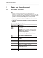
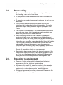
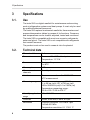
testo 550 · Digital manifold Instruction manual 2 1 Contents 1 Contents 1 Contents ...................................................................................................3 2 Safety and the environment....................................................................4 3 4 2.1. About this document ........................................................................4 2.2. Ensure safety...................................................................................5 2.3. Protecting the environment..............................................................5 Specifications ..........................................................................................6 3.1. Use ..................................................................................................6 3.2. Technical data .................................................................................6 Product description.................................................................................8 4.1. Overview..........................................................................................8 5 First steps ................................................................................................9 6 Using the product ..................................................................................11 6.1. Preparing for measurement ...........................................................11 6.1.1. 6.1.2. 6.1.3. 6.2. Connecting the temperature sensor ...............................................................11 Switching the instrument on ...........................................................................12 Selecting the measuring mode.......................................................................13 Performing the measurement ........................................................14 7 Maintaining the product ........................................................................16 8 Tips and assistance...............................................................................18 8.1. Questions and answers .................................................................18 8.2. Measurement parameters .............................................................18 8.3. Error reports ..................................................................................19 8.4. Accessories and spare parts .........................................................19 3 2 Safety and the environment 2 Safety and the environment 2.1. About this document Use > Please read this documentation through carefully and familiarize yourself with the product before putting it to use. Pay particular attention to the safety instructions and warning advice in order to prevent injuries and damage to the products. > Keep this document to hand so that you can refer to it when necessary. > Hand this documentation on to any subsequent users of the product. Symbols and writing standards Representation Explanation Warning advice, risk level according to the signal word: Warning! Serious physical injury may occur. Caution! Slight physical injury or damage to the equipment may occur. > Implement the specified precautionary measures. Note: Basic or further information. 2. ... Action: more steps, the sequence must be followed. > ... Action: a step or an optional step. - Result of an action. 1. ... 4 ... Menu Elements of the instrument, the instrument display or the program interface. [OK] Control keys of the instrument or buttons of the program interface. ... | ... Functions/paths within a menu. “...” Example entries 2 Safety and the environment 2.2. Ensure safety > Do not operate the instrument if there are signs of damage at the housing, mains unit or feed lines. > Do not perform contact measurements on non-insulated, live parts. > Do not store the product together with solvents. Do not use any desiccants. > Carry out only the maintenance and repair work on this instrument that is described in the documentation. Follow the prescribed steps exactly. Use only original spare parts from Testo. > The objects to be measured or the measurement environment may also pose risks: Note the safety regulations valid in your area when performing the measurements. > If the measuring instrument falls or another comparable mechanical load occurs, the pipe sections of the refrigerant hoses may break. The valve positioners may also be damaged, whereby further damage to the interior of the measuring instrument may occur that cannot be identified from the outside. The refrigerant hoses must therefore be replaced with new, undamaged refrigerant hoses every time the measuring instrument falls or following any other comparable mechanical load. Send the measuring instrument to Testo Customer Service for a technical check for your own safety. > Electrostatic charging can destroy the device. Integrate all the components (system, manifold's valve block, refrigerant bottle etc.) into the potential equalisation (earthing). Please see the safety instructions for the system and the refrigerant used. 2.3. Protecting the environment > Dispose of faulty rechargeable batteries/spent batteries in accordance with the valid legal specifications. > At the end of its useful life, send the product to the separate collection for electric and electronic devices (observe local regulations) or return the product to Testo for disposal. > Refrigerant gases can harm the environment. Please note the applicable environmental regulations. 5 3 Specifications 3 Specifications 3.1. Use The testo 550 is a digital manifold for maintenance and servicing work at refrigeration systems and heat pumps. It must only be used by qualified authorized personnel. The testo 550 replaces mechanical manifolds, thermometers and pressure/temperature tables by means of its functions. Pressures and temperatures can be loaded, adjusted, tested and monitored. The testo 550 is compatible with most non-corrosive refrigerants, water and glycol. The testo 550 is not compatible with refrigerants that contain ammonia. The product must not be used in areas at risk of explosion! 3.2. Technical data Characteristic Values Parameters Pressure: kPa / MPa / bar / psi Temperature: °C/°F/K Sensor Pressure: 2 x pressure sensor, temperature: 2 x NTC Meas. cycle 0.75 s Measurement channels Quantity: 4 Interfaces Pressure connections: 3 x 7/16" UNF NTC measurement Measuring ranges Pressure measuring range HP/LP: -1 to 50 bar (rel)/-14.7 to 725 psi (rel)/ 100 to 5000 kPa (rel)/0.1 to 5 MPa (rel) Temperature measuring range: -50 to +150 °C/-58 to 302 °F Humidity application 10 to 90 % RH range Overload 60 bar, 6000 kPa, 6 MPa, 870 psi Resolution Pressure resolution: 0.01 bar/0.1 psi/ 1 kPa/0.001 MPa Temperature resolution: 0.1 °C/0.1 °F 6 3 Specifications Characteristic Values Accuracy (nominal temperature 22 °C/71.6 °F) Pressure: ±0.75 % of final value (±1 digit) No. of refrigerants 40 Selectable refrigerants No refrigerant, R12, R22, R123, R134a, R290, R401A, R401B, R402A, R402B, R404A, R406A, R407A, R407C, R408A, R409A, R410A, R411A, R413A, R414B, R416A, R417A, R420A, R421A, R421B, R422A, R422B, R422D, R424A, R427a, R434A, R437A, R438A, R502, R503, R507, R600, R600a, R718 (H2O), R744 (only in permissible measuring range up to 50 bar), R1234yf (Display: T8) Measurable media Measurable media: All media that are stored in the testo 550. Not measurable: Ammonia (R717) and other refrigerants which contain ammonia Ambient conditions Operating temperature: -10 to 50 °C/ 14 to 122 °F Temperature (-40…150°C): ±0.5 K (±1 digit) Storage temperature: -20 to 60 °C/ -4 to 140 °F Housing Material: ABS/PA/TPU Dimensions: 265 x 135 x 75 mm Weight: approx. 1000 g (without batteries) Power supply Current source: Rechargeable batteries/batteries 4x 1.5 V, type AA/mignon/LR6 Battery life: approx. 150 h (display light off) Display Type: Illuminated LCD Updating of readings: 1 s Response time: 0.5 s Directives, EC Directive: 2004/108/EC standards and tests Warranty Duration: 2 years Warranty conditions: see website www.testo.com/warranty 7 4 Product description 4 Product description 4.1. Overview Display and control elements 1 Mini-DIN probe socket for NTC temperature probe, with socket cover 2 Foldable suspension device (on rear) 3 Display. Instrument status icons: Icon Significance Battery capacity: >75 %/>50 %/>25 %/<10 % / / Select measuring mode (see) 4 Battery compartment. It is not possible to charge rechargeable batteries in the instrument! 8 5 First steps 5 Control keys: Key Function [Set] Set units [R, Start/ Stop] Select refrigerant/ Start/stop / Tightness test [Mode] Switching measuring mode [Min/Max/Mean] Display min./max./mean values [▲] Up key: Change display view [p=0] Pressure zeroing Light key: Switch display light on/off [▼] [ Down key: Change display view Switching the instrument on/off ] 6 Sight glass for refrigerant flow 7 2 x valve positioner 8 3 x hose parkers for refrigerant hoses 9 3 x connections 7/16" UNF, brass Left/right: Low pressure/high pressure, for refrigerant hoses with quick connect fitting, passage can be locked via valve positioner. Centre: for refrigerant bottles, for example, with sealing cap. 5 First steps Inserting batteries/rechargeable batteries 1. Fold out the suspension device and open the battery compartment (clip lock). 2. Insert batteries (included in delivery) or rechargeable batteries (4x 1.5 V, type AA/Mignon/LR6) in the battery compartment. Observe the polarity! 3. Close the battery compartment. When not in use for long period: Remove batteries/rechargeable batteries. Completely charge rechargeable batteries before using the instrument. 9 5 First steps Switching the instrument on > Press [ ]. - Initialization phase: - Measurement view is opened. • All display segments are lit (length of time: 2 s). Performing settings 1. Press [Set]. - The configuration menu is opened and the adjustable parameter flashes. 2. Set parameters: Key functions Representation Explanation [▲] or [▼] Change parameter, select unit [Set] Select units/parameters Adjustable parameters Representation Explanation °C, °F Set temperature unit. bar, kPa, MPa, psi Set unit of pressure. Pabs, Prel or psia, Depending on the selected unit of pressure: psig Switch between absolute and relative pressure display. 29.92 inHg/ 1.013 bar / / Set current absolute pressure (see table) Select measuring mode (see Selecting the measuring mode, page 13) Settings will be applied following the final selection. Operating valve positioner The digital manifold acts like a conventional two-way manifold with regard to the refrigerant path: The passages are opened by opening the valves. The adjacent pressure is measured with valves closed as well as with them open. > Open valve: Turn valve positioner anticlockwise. > Close valve: Turn valve positioner clockwise. 10 6 Using the product WARNING Only tighten valve positioner with your hand! Do not use any tools when tightening as otherwise the thread may be damaged. 6 Using the product 6.1. Preparing for measurement 6.1.1. Connecting the temperature sensor Sensors must be connected before the measuring instrument is switched on, so that they are recognised by the instrument. Surface temperature sensor An NTC temperature sensor (accessory) must be connected for measuring the pipe temperature and for automatic calculation of superheating and subcooling. Deactivating the surface compensation factor for insertion and air temperature sensor A surface compensation factor has been set in the measuring instrument to reduce the measuring errors in the main field of applications. This reduces measuring errors when using surface temperature sensors. If the measuring instrument testo 550 is used in combination with insertion or air temperature sensors (accessories), this factor must be deactivated: > Press and hold the keys SET + MODE together and switch on the measuring instrument [ ]. - The instrument shows the message Fact off. The surface compensation factor becomes active every time the measuring instrument is switched on. 11 6 Using the product 6.1.2. Switching the instrument on > Press [ ]. Zeroing the pressure sensors Zero the pressure sensors before every measurement. ✓ All connections must be pressureless (ambient pressure). > Press key [P=0] and execute zeroing. Connecting the refrigerant hoses Before each measurement check whether the refrigerant hoses are in flawless condition. ✓ The valve actuators are closed. 1. Connect the refrigerant hoses for low-pressure side (blue) and high-pressure side (red) to the measuring instrument. 2. Connect the refrigerant hoses to the system. WARNING The measuring instrument dropping down or any other comparable mechanical load can cause breakage of the pipe pieces in the refrigerant hoses. The valve actuators may also suffer damage, which in turn could result in further damage inside the measuring instrument, which may not be detectable from outside. > For your own safety you should return the measuring instrument to the Testo Service for technical inspection. > You should therefore always replace the refrigerant hoses with new ones after the measuring instrument has dropped down or after any comparable mechanical loading. Setting the refrigerant 1. Press [R, Start/Stop]. - This opens the refrigerant menu and the currently selected refrigerant flashes. 2. Setting the refrigerant: 12 6 Using the product Key functions Representation Explanation [▲] or [▼] Changing the refrigerant [R, Start/Stop] Confirm the setting and exit the refrigerant menu. Available refrigerants Representation Explanation R... Refrigerant number of refrigerant acc. to ISO 817 T... Special Testo designation for certain refrigerants (T8 = T1234yf) --- no refrigerant selected. Example: Setting refrigerant R401B 1. Press [▲] or [▼] several times, until R401B flashes. 2. Press [R, Start/Stop] to confirm the setting. Quitting the refrigerant selection > Press [R, Start/Stop] or automatically after 30 s, if no other key has been pressed. 6.1.3. Selecting the measuring mode 1. Press[Set] several times. 2. Select function with[▲] or [▼]. 3. Save setting: press [Set]. - Measuring mode is dsplayed. Display Mode Function Refrigeration Normal functionality of the digital manifold system Heat pump Normal functionality of the digital manifold Automatic mode If the automatic mode is activated, the testo 550 digital manifold automatically changes the display of the high and low pressure. This automatic change occurs when the pressure on the low-pressure side is 1 bar higher than the pressure on the high-pressure side. During the change, Load (2 s) is shown in the 13 6 Using the product Display Mode Function display. This mode is especially suited to air conditioning systems which cool and heat. 6.2. Performing the measurement WARNING Risk of injury caused by refrigerant that is at high pressure, hot, cold, or poisonous! > Wear safety goggles and protective gloves. > Before pressurizing the measuring instrument: Always fasten the measuring instrument at the suspension device in order to prevent it from falling (risk of breakage) > Check if the refrigerant hoses are intact and connected correctly before each measurement. Do not use a tool to connect the hoses. Only tighten the hoses by hand (max. torque 5.0 Nm/3.7 ft*lb). > Maintain permissible measuring range (0 to 50 bar). Pay particular attention with systems with refrigerant R744, as these are often operated with higher pressures. Measuring ✓ The steps described in the chapter "Preparing for measurement" have been completed. 1. Pressurize the measuring instrument. 2. Read off readings. With zeotropic refrigerants, the evaporation temperature to/Ev is displayed after the complete evaporation/the condensation temperature tc/Co is displayed after the complete condensation. The measured temperature must be assigned to the superheating or the subcooling side (toh <--> tcu). Depending on this assignment, toh/T1 or Δtoh/SH or tcu/T2 or Δtcu/SC is shown depending on the selected display. 14 6 Using the product - Reading and display illumination flash: • 1 bar before reaching the critical pressure of the refrigerant, • upon exceeding the max. permissible pressure of 50 bar. Key functions > [▲] or [▼]: Change the reading display. Possible display combinations: Evaporation pressure Refrigerant evaporation temperature to/Ev Condensation pressure Refrigerant condensation temperature tc/Co or (only with connected temperature probe) Condensation pressure Evaporation pressure Measured temperature toh/T1 Measured temperature tcu/T2 or (only with connected temperature probe) Evaporation pressure Superheating Δtoh/SH. Condensation pressure Subcooling Δtcu/SC With two connected NTC probes, Δt is also shown. > [Mean/Min/Max]: Record readings, display min./max. readings, mean values (since switching on). Tightness test/pressure drop test Systems can be tested for tightness with the temperature-compensated tightness test. The system pressure and the ambient temperature are measured over a defined period for this. A temperature probe can be connected that measures the ambient temperature for this (recommendation: NTC air probe, art. no. 0613 1712). Information about the temperature-compensated differential pressure and about the temperature at the beginning/end of the test exists as a result. If no temperature probe is connected, the tightness test can be performed without temperature compensation. ✓ The steps described in the chapter "Preparing for measurement" have been completed. 1. Press [Mode] (leakage test view). - Leakage test view is opened. ΔP is displayed. 2. Start the leakage test: Press [R, Start/Stop]. 3. End the leakage test: Press [R, Start/Stop]. 15 7 Maintaining the product - Result is displayed. 4. Confirm message: Press [Mode]. - You automatically jump to the evacuation/vacuum display menu. Evacuation/vacuum display The measurement is performed on the low-pressure side. 5. Press [Mode]. - Result is displayed on the low-pressure side. 6. Press [Mode]. - 7 The measuring mode is displayed. Maintaining the product Cleaning the instrument > If the housing of the instrument is dirty, clean it with a damp cloth. Do not use any aggressive cleaning agents or solvents! Weak household cleaning agents and soap suds may be used. Keeping connections clean > Keep screw connections clean and free of grease and other deposits, clean with a moist cloth as required. Removing oil residues > Carefully blow out oil residues in valve block using compressed air. Ensuring the measuring accuracy Testo Customer Service would be glad to further assist you if you so wish. > Check instrument regularly for leaks (recommended: annually). Keep to the permissible pressure range! > Calibrate instrument regularly (recommended: annually). 16 7 Maintaining the product Changing batteries/rechargeable batteries ✓ Instrument is switched off. 1. Fold out the suspension device, loosen the clip and remove the cover of the battery compartment. 2. Remove empty batteries/rechargeable batteries and insert new batteries/rechargeable batteries (4x 1.5 V, type AA, Mignon, LR6) in the battery compartment. Observe the polarity! 3. Set on and close cover of the battery compartment (clip must engage). 4. Switch the instrument on. Changing the valve or valve positioner handle WARNING Change of the valve positioners and valves by the customer is not permissible. > Send the measuring instrument to the Testo Customer Service. 17 8 Tips and assistance 8 Tips and assistance 8.1. Questions and answers Question Possible causes/solution Batteries are almost empty. flashes > Change batteries. The instrument switches off automatically. Residual capacity of the batteries is too low. > Change batteries. uuuu lights up instead of the parameter display The permissible measuring range has been undershot. > Keep to the permitted measuring range. oooo lights up instead of the parameter display The permissible measuring range has been exceeded. > Keep to the permitted measuring range. 8.2. Measurement parameters Name 18 Description Δtoh SH Superheating, evaporation pressure Δtcu SC Subcooling, condensation pressure to Ev Refrigerant evaporation temperature tc Co Refrigerant condensation temperature toh T1 Measured temperature, evaporation tcu T2 Measured temperature, condensation 8 Tips and assistance 8.3. Error reports Question Possible causes/solution ---- is lit up instead of measurement parameter display Sensor or cable defective Display EEP FAIL Eeprom defective > Please contact your dealer or Testo Customer Service > Please contact your dealer or Testo Customer Service 8.4. Accessories and spare parts Description Article no. Clamp probe for temperature measurement at pipes 0613 5505 Pipe wrap probe with Velcro tape for pipe diameters of up to max. 75 mm, Tmax. +75 °C, NTC 0613 4611 Watertight NTC surface probe 0613 1912 Precise, robust NTC air probe 0613 1712 Transport case for measuring instrument, probe and hoses 0516 5505 For a complete list of all accessories and spare parts, please refer to the product catalogues and brochures or look up our website at: www.testo.com If you have any questions, please contact your dealer or Testo Customer Service. The contact details can be found on the back of this document or on the Internet at www.testo.com/servicecontact.. 19 0970 5501 en 06 V01.16