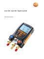
1
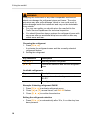
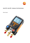
testo 549 - testo 550 . Digital manifold Instruction manual 2 1 Contents 1 Contents 1 Contents ...................................................................................................3 2 Safety and the environment....................................................................4 2.1. About this document ........................................................................4 2.2. Ensure safety...................................................................................4 2.3. Protecting the environment ..............................................................5 3 Product description .................................................................................5 3.1. Use ..................................................................................................5 3.2. Overview .........................................................................................6 4 First steps ................................................................................................7 5 Using the manifold ..................................................................................9 5.1. Preparing for measurement .............................................................9 5.1.1. 5.1.2. 5.1.3. 5.1.4. 5.2. 6 Switching the instrument On ...............................................................................9 Connecting temperature probe(s) .....................................................................11 Switching Bluetooth® on and off (only testo 550) ............................................11 Measuring mode ...............................................................................................12 Performing the measurement ........................................................ 13 Technical data ........................................................................................ 16 6.1.1. 6.1.2. Bluetooth module (only testo 550) ....................................................................16 General technical data ......................................................................................17 7 Maintaining the product ........................................................................19 8 Tips and assistance............................................................................... 20 8.1. Questions and answers .................................................................20 8.2. Measurement parameters ............................................................. 20 8.3. Error reports .................................................................................. 21 8.4. Accessories and spare parts ......................................................... 21 9 EC declaration of conformity ................................................................ 22 3 2 Safety and the environment 2 Safety and the environment 2.1. About this document Use > Please read this documentation carefully and familiarize yourself with the product before putting it to use. Pay particular attention to the safety instructions and warning advice in order to prevent injuries and damage to the product. Symbols and writing standards Representation Explanation Warning advice, risk level according to the signal word: Warning! Serious physical injury may occur. Caution! Slight physical injury or damage to the equipment may occur. > Implement the specified precautionary measures. Menu Elements of the instrument, the instrument display or the program interface. [OK] Control keys of the instrument or buttons of the program interface. 2.2. Ensure safety > Do not operate the instrument if there are signs of damage at the housing, mains unit or hoses. > Do not store the product together with solvents. Do not use any desiccants. > Carry out only the maintenance and repair work on this instrument that is described in the documentation. > Dangers may also arise from the refrigeration systems being measured or the measuring environment: Note the safety regulations valid in your area when performing the measurements. 4 3 Product description > If the manifold falls or another comparable mechanical load occurs, the pipe sections of the refrigerant hoses may break. The valve stem shutoff may also be damaged, whereby further damage to the interior of the manifold may occur that cannot be identified from the outside. The refrigerant hoses must therefore be replaced with new, undamaged refrigerant hoses every time the manifold falls or following any other comparable mechanical load. Send the manifold to Testo Customer Service for a technical check for your own safety. > To prevent damage from ESD (electro-static discharge) or transient voltage spikes make sure that your refrigeration system is properly grounded, as otherwise the manifold might get damaged. 2.3. Protecting the environment > Dispose of spent batteries in accordance with the valid legal specifications. > At the end of its useful life, send the product to the separate collection for electric and electronic devices (observe local regulations) or return the product to Testo for disposal. > Refrigerant gases can harm the environment. Please note the applicable environmental regulations. 3 Product description 3.1. Use Testo 549 and testo 550 are digital manifolds for maintenance and service work on refrigeration systems and heat pumps. They are intended for use by qualified personnel only. The functions of the testo 549 and testo 550 are designed to replace analog manifolds, thermometers and pressure/temperature charts. Pressures and temperatures can be applied, adapted, tested and monitored. Testo 549 and testo 550 are compatible with most non-corrosive refrigerants, water and glycol. Testo 549 and testo 550 are not compatible with refrigerants containing ammonia. The instruments must not be used in explosive environments! 5 3 Product description 3.2. Overview Display and control elements 1 Mini-DIN probe socket for NTC temperature probe, with socket cover 2 Foldable hanging hook (on rear) 3 Display. Instrument status icons: Icon Significance Battery status Bluetooth® / / Measuring mode 4 Battery compartment. NOTE: Rechargeable batteries cannot be charged inside the battery compartment. 6 4 First steps 5 Control keys: Key Function [Set] Set units [R, ►, ■] Select refrigerant/ Start/stop / Leakage test [Mode] Change measuring mode to Leak mode [Min/Max/Mean] Display min./max./mean values [▲] Up key: Scroll through menu [P=0] Pressure zeroing Esc Switches to the measurement / home view [▼] Down key: Scroll through menu [ / ] Switching the instrument on/off Switch the display illumination on/off. 6 7 8 9 Sight glass for refrigerant flow 2 x valve stem shutoff 3 x hose holders for refrigerant hoses 3 x connections 1/4" SAE, brass Left/right: Low pressure/high pressure, for refrigerant hoses with quick connect fitting Center: for charge / discharge of refrigerant 10 Mini-USB connection for firmware update, inside the battery compartment. 4 First steps Inserting batteries / rechargeable batteries 1. Fold out the hanging hook and open the battery compartment by squeezing the clip lock. 2. Insert batteries (included in delivery) or rechargeable batteries (4x 1.5 V, type AA/Mignon/LR6) in the battery compartment. Observe the polarity! 3. Close the battery compartment. - After inserting the batteries, the instrument switches on automatically and goes into the settings menu. When not in use for long period: Remove batteries/rechargeable batteries. 7 4 First steps Units / Parameter selection 1. Press [Set] to confirm or change unit parameter settings 2. Press [▲] or [▼] to change the units / parameters. The settings will be accepted once the last selection has been made. Key functions Description [▲] or [▼] Change parameters and select units [Set] Confirm units / parameters Selectable parameters Description °F, °C Temperature unit Psi, bar, kPa, MPa Unit of pressure Psig or Pabs, Prel Switch between absolute and relative pressure display Pamb / Set current absolute pressure in inches of HG or bar / AUTO OFF Tfac Select measuring mode: heat pump / cooling / or Auto Activate or deactivate Automatic power-off. Instrument switches off after 30 minutes if no temperature probe is connected and there is no pressure apart from ambient pressure Activate or deactivate surface temperature compensation factor, icon is shown on the display if the function is deactivated Settings will be applied following the final selection. Operating valve stem shutoffs The digital manifold acts like a conventional two-way manifold with regard to the refrigerant path: The passages are opened by opening the valves. The adjacent pressure is measured with valves closed as well as with them open. > Open valve: Turn valve positioner counterclockwise. > Close valve: Turn valve positioner clockwise. 8 5 Using the manifold WARNING Over tightening the valve stem shutoffs may cause: • Damage to the PTFE seal. • Mechanical deformation of the valve piston leading to the PTFE seal falling out. • Damage to the thread of the threaded spindle and the valve screw. • valve knobs to brake. Lightly tighten the valve knob. Do not use tools to tighten the valve stem shutoffs. 5 Using the manifold 5.1. Preparing for measurement 5.1.1. Switching the instrument On > Press [ / ]. Zero the pressure sensors before every measurement. ✓ All connections must be at ambient pressure. > Press [P=0] key for 3 seconds to execute zeroing. Connecting the refrigerant hoses Before each measurement check whether the refrigerant hoses are in flawless condition. ✓ Make sure the valve stem shutoffs are closed. 1. Connect the refrigerant hoses to the low-pressure side (blue) and high-pressure side (red). 2. Connect the refrigerant hoses to the AC/R system. 9 5 Using the manifold WARNING Dropping this instrument or any other comparable mechanical shock can damage the refrigerant pipes and hoses. The valve actuators may also suffer damage, which in turn could result in further damage inside the instrument and may not be detectable from outside. > For your own safety you should return the manifold to the Testo Service Department for technical inspection. > You should therefore always replace the refrigerant hoses with new ones after an accidental drop has occurred or after any visible wear and tear. Choosing the refrigerant 1. Press [R, ►, ■]. - It activates the refrigerant menu and the currently selected refrigerant flashes. 2. Setting the refrigerant: Key functions Description [▲] or [▼] Selecting another refrigerant [R, ►, ■] Confirm the selection and exit the refrigerant menu Available refrigerants Representation Description R... Refrigerant number of refrigerant acc. to ISO 817 --- no refrigerant selected. Example: Selecting refrigerant R401B 1. Press [R, ►, ■] to activate refrigerant menu. 2. Press [▲] or [▼] several times, until R401B flashes. 3. Press [R, ►, ■] to confirm the selection. Exiting the refrigerant selection > Press [R, ►, ■] or automatically after 30 s, if no other key has been pressed. 10 5 Using the manifold 5.1.2. Connecting temperature probe(s) Note: The testo 549 does not include temperature probes in the initial scope of delivery. Surface temperature probe At least one NTC temperature probe must be connected to measure the pipe temperature, for automatic calculation of superheating and subcooling. Deactivating the surface compensation factor for insertion and air temperature probes A surface compensation factor has been set in the measuring instrument to improve the measuring accuracy of surface temperature readings. If the manifold is used in combination with insertion or air temperature probe (optional), this factor must be deactivated: 1. Press [Set] repeatedly until Tfac is displayed. 2. Press [▲] or [▼] to set Tfac to Off. 3. Press [Set] to continue through the settings menu until the measurement/home view is displayed. - Tfac is shown on the display if Tfac is disabled. 5.1.3. Switching Bluetooth® on and off (only testo 550) In order to to establish a connection via Bluetooth, on an Android or iOS device, the Testo App Refrigeration must be already installed. You can download the App for iOS in the Apple App Store or for Android in Google Play. The App is compatible with devices using iOS 7 or higher / Android 4.3 or 4.4. 1. To turn on the Bluetooth press [▲] and [▼] simultaneously and hold down for 3 seconds. - Once the Bluetooth icon is shown on the display, Bluetooth is switched on. Display flashes is permanently displayed Description There is no Bluetooth connection, or a potential connection is being searched for. There is a Bluetooth connection. 11 5 Using the manifold Display Description is not displayed Bluetooth is disabled. 2. To turn off the Bluetooth press [▲] and [▼] simultaneously and hold down for 3 seconds. - Once the Bluetooth icon is no longer shown on the display, Bluetooth is switched off. 5.1.4. Measuring mode Display 12 Mode Function Refrigeration system Normal functionality of the digital manifold Heat pump Normal functionality of the digital manifold Automatic mode If the automatic mode is activated, the testo 549 und testo 550 digital manifolds automatically changes the display of the high and low pressure. This automatic change occurs when the pressure on the low-pressure side is 1 bar (15 psi) higher than the pressure on the high-pressure side. During the change, Load (2 s) is shown in the display. This mode is especially suited to air conditioning systems which cool and heat (heat pumps). 5 Using the manifold 5.2. Performing the measurement WARNING Risk of injury caused by refrigerant that is at high pressure, hot, cold, or poisonous! > Wear safety goggles and protective gloves. > Before pressurizing the measuring instrument: Always fasten the measuring instrument at the hanging hook in order to prevent it from falling (risk of breakage) > Check if the refrigerant hoses are intact and connected correctly before each measurement. Do not use a tool to connect the hoses. Only tighten the hoses by hand (max. torque 5.0 Nm/3.7 ft*lb). > Do not exceed the permissible measuring range (0 to 870 psi / 0 to 60 bar). Pay particular attention with systems with refrigerant R744, as these are often operated with higher pressures. Measuring 1. Connect and apply pressure to the manifold. 2. See readings. Note: With refrigerants that have a temperature glide, “Zeotropes” the evaporation temperature Ev/to and condensation temperature Co/tc are displayed after evaporation and condensation are complete. Zeotropes (refrigerants blends mix together) can separate from each other, unlike azeotropes which mix together to become one. Zeoptropes often blend refrigerants with different boiling points (saturation temps), where one will change from liquid to vapor before the other as they go through the evaporator. The glide is the difference between the lowest boiling point and the highest boiling point. If they are 3 degrees apart, for example, the blend has a 3 degree glide. 13 5 Using the manifold The display illumination will flash if: • The critical pressure of the refrigerant is within 15 psi (1 bar) of the highest pressure (and temperature) where the refrigerant can still condense • The maximum. permissible pressure of 870 psi (60 bar) is exceeded. Key functions for 550 or 549 when used with optional probes > Press [▲] or [▼] to change the reading in the display. (The temperature probes must be connected.) Possible display combinations: Refrigerant evaporation temperature Ev/to (°F/°C) Refrigerant condensation temperature Co/tc (°F/°C) Evaporation pressure (psi/bar) Condensation pressure (psi/bar) Measured temperature T1/toh Measured temperature T2/tcu (°F/°C) (°F/°C) Evaporation pressure (psi/bar) Condensation pressure (psi/bar) Superheating SH/Δtoh (°F/°C) Subcooling SC/Δtcu (°F/°C) Evaporation pressure (psi/bar) Changeable - Evaporation Temperature (Ev) - Measured Temperature (T1) - Superheating (SH) Evaporation pressure Condensation pressure (psi/bar) Changeable - Condensation Temperature (Co) - Measured Temperature (T2) - Subcooling (SC) Condensation pressure With both NTC temperature probes connected, Δt is also shown. > Press [Mean/Min/Max] to display min./max. readings and mean values. 14 5 Using the manifold Leak test / pressure drop test Systems can be tested for tightness with the temperaturecompensated leak test. The system pressure and the ambient temperature are measured over a defined period of time, typically with an inert gas such as Nitrogen. A temperature probe can be connected that measures the ambient temperature. : Optional air temperature probe, part. no. 0613 1712) is recommended. Measurement data of the temperature-compensated differential pressure and temperature, from start to the end of the test, is displayed. It is possible to perform a leak test without connecting a temperature probe. 1. Press [Mode] ΔP is displayed. 2. Start the leakage test: Press [R, ►, ■].ΔP is now flashing and hh:mm timer is on. 3. End the leakage test: Press [R, ►, ■]. ΔP stops flashing and hh:mm timer stops. - Result is displayed. Note: Leak test time duration and ΔP value 4. Confirm message: Press [Mode] to exit leak mode. Duration of test Measured pressure beginning of test Differential pressure start compared to actual Actual measured pressure 15 6 Technical data 6 Technical data 6.1.1. Bluetooth module (only testo 550) ® The Bluetooth option may only be operated in countries in which it is approved. Feature Values Bluetooth type LSD Science & Technology Co., Ltd L Series BLE module (08 May 2013) based on TI CC254X chip Qualified Design ID B016552 Bluetooth radio class Class 3 Bluetooth listing company 10274 European Union Germany (DE), Belgium (BE), Netherlands (NL), Spain (ES), Sweden (SE), Italy (IT), Denmark (DK), United Kingdom (GB), France (FR), Austria (AT), Poland (PL), Hungary (HU), Romania (RO), Czech Republic (CZ), Finland (FI), EFTA countries Switzerland (CH), Norway (NOR) Other countries Turkey (TR), India (IN), Australia (AUS), New Zealand (NZL), USA (US), Argentina (AR), Hong Kong (HK) Information from the FCC (Federal Communications Commission) This device complies with part 15 of the FCC Rules. Its commissioning is subject to the following two conditions: (1) This device may not cause harmful interference and (2) this device must be able to accept interference, even if this could have undesired effects on the operation. Changes The FCC demands that the user be informed that any changes or modifications to the instrument that are not explicitly approved by testo AG may void the user's right to use this instrument. 16 6 Technical data 6.1.2. General technical data Characteristic Values Parameters Pressure: kPa / MPa / bar / psi Temperature: °C / °F / K Sensors 2 Pressure: sensors, 2 Temperature (NTC Thermistors) Meas. cycle 0.5 s Interfaces Pressure connections: 3 x 1/4" SAE 2 Temperature NTC measurement channels Measuring ranges HP/LP pressure measuring range: -100 to 6000 kPa / -0.1 to 6 MPa / -1 to 60 bar (rel) / -14.7 to 870 psi Temperature measuring range: -50 to +150 °C / -58 to 302°F Vacuum measuring range (rel): -1 to 0 bar / -14.7 to 0 psi Overload 65 bar, 6500 kPa, 6.5 MPa, 940 psi Resolution Pressure resolution: 0.01 bar / 0.1 psi / 1 kPa / 0.001 MPa Temperature resolution: 0.1 °C/0.1 °F Accuracy (nominal temperature 22 °C/71.6 °F) Pressure: ± 0.5 % FS Temperature 58 to 302°F (0.9°F ± 1 digit) 0 to 150°C (±0.5 °C ±1 digit) No. of refrigerants 60 Selectable refrigerants No refrigerant, R11, R12, R22, R123, R1234ze, R125, R13B1, R134a, R14, R142B, R152a, R161, R23, R227, R290, R32, R401A, R401B, R401C, R402A, R402B, R404A, R406A, R407A, R407B, R407C, R407D, R407F, R408A, R409A, R410A, R411A, R412A, R413A, R414B, R416A, R417A, R420A, R421A, R421B, R422A, R422B, R422C, R422D, R424A, R426A, R427A, R434A, R437A, R438A, R502, R503, R507, R508A, R508B, R600, R600a, R718 (H2O), R744 (CO2) (only in measuring range up to 870 psi (60 bar), R1234yf 17 6 Technical data Measurable media All refrigerants that are stored in the testo 549 and testo 550 Ammonia (R717) and other refrigerants which contain ammonia will damage the manifold Ambient conditions Operating temperature: -4 to 122 °F (-20 to 50 °C) Storage temperature: -4 to 140 °F (-20 to 60 °C) Bluetooth Range >20 m / 65 ft (unobstructed field) Housing Material: ABS/PA/TPU Dimensions: 7.87 x 4.29 x 2.48 in. (265 x 135 x 75 mm) Weight: approx. 2.83 lbs. 1060 g (without batteries) IP class 42 Power supply 4 x 1.5 V, type AA/mignon/LR6 rechargeable or standard batteries Battery life: approx. 250h (display light off, Bluetooth off) Display Type: Illuminated LCD Response time: 0.5 s EC Directive: 2014/30/EC Directives, standards and tests Warranty 18 Duration: 2 years Warranty conditions: see website www.testo.com/warranty 7 Maintaining the product 7 Maintaining the product Cleaning the instrument Do not use harsh cleaning agents or solvents! Mild soap and water may be used. > Clean instrument using a damp cloth. Keeping connections clean > Keep screw connections clean and free of grease and other deposits, clean with a moist cloth as required. Removing oil residues > Carefully blow out oil residues in valve block using compressed air. To ensure measuring accuracy > Check instrument regularly for leaks (recommended: annually). Do not exceed the pressure range! > Calibrate instrument regularly (recommended: annually). Changing batteries/rechargeable batteries ✓ Instrument is switched off. 1. Fold out the hook, loosen the clip and remove the cover of the battery compartment. 2. Remove discharged batteries/rechargeable batteries and insert new batteries/rechargeable batteries (4x 1.5 V, type AA, Mignon, LR6) in the battery compartment. Observe the polarity! 3. Set on and close cover of the battery compartment (clip must engage). 4. Switch the instrument on. 19 8 Tips and assistance Changing the valve or valve stem shutoff DO NOT ATTEMPT to change the valve stems. Changing the valve stem shutoff or valves themselves will void the warranty. Send the measuring instrument to Testo Customer Service. 8 Tips and assistance 8.1. Questions and answers Question Possible causes/solution Batteries are nearly discharged. > Replace batteries. flashes The instrument switches off automatically. uuuu lights up instead of the parameter display oooo lights up instead of the parameter display 8.2. 20 Batteries are discharged. > Replace batteries. The maximum measurement range has been exceeded. Under range value has been exceeded. Measurement parameters bar, °C psi, °F Description Δtoh SH Superheating, evaporation pressure Δtcu SC Subcooling, condensation pressure to Ev Refrigerant evaporation temperature tc Co Refrigerant condensation temperature toh T1 Measured temperature, evaporation tcu T2 Measured temperature, condensation 8 Tips and assistance 8.3. 8.4. Error reports Question Possible causes/solution ---- is lit up instead of measurement parameter display Sensor or cable defective > Please contact your dealer or Testo Customer Service Display EEP FAIL Electronics (Hardware Fault) > Please contact Testo Customer Service Accessories and spare parts Description Article no. Temperature clamp probe - 4.9 ft. cable length (1.5m) 0613 5505 Temperature clamp probe - 14 ft. cable length (5m) 0613 5506 Pipe wrap probe with Velcro tape 0613 4611 Watertight NTC surface probe 0613 1912 Precise, robust NTC air probe 0613 1712 Transport case for measuring instrument, probe and hoses 0516 0012 For a complete list of all accessories and spare parts, please refer to the product catalogues and brochures or look up our website at: www.testo.com If you have any questions, please contact your dealer or Testo Customer Service. The contact details can be found on the back of this document or on the Internet at www.testo.com/servicecontact. Click onto your country’s flag for local support. 21 9 EC declaration of conformity 9 22 EC declaration of conformity 9 EC declaration of conformity 23 Testo Inc. 40 White Lake Road Sparta, N. J. 07871 Phone: +1 862 354 5001 Fax: +1 862 354 5020 Email: [email protected] www.testo.com Headquarter testo AG Testo-Straße 1 79853 Lenzkirch Germany Tel.: +49 7653 681-0 Fax: +49 7653 681-7699 Email: [email protected] Internet: www.testo.de 0970 5502 en-US 01 V02.00