1
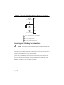
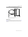
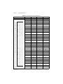
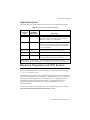
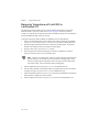
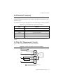
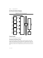
NI SC Express NI PXIe-4357 User Manual Subtitle NI PXIe-4357 User Manual March 2012 373440A-01 Support Worldwide Technical Support and Product Information ni.com Worldwide Offices Visit ni.com/niglobal to access the branch office Web sites, which provide up-to-date contact information, support phone numbers, email addresses, and current events. National Instruments Corporate Headquarters 11500 North Mopac Expressway Austin, Texas 78759-3504 USA Tel: 512 683 0100 For further support information, refer to the Technical Support and Professional Services appendix. To comment on National Instruments documentation, refer to the National Instruments Web site at ni.com/info and enter the Info Code feedback. © 2012 National Instruments Corporation. All rights reserved. Important Information Warranty The NI PXIe-4357 is warranted against defects in materials and workmanship for a period of one year from the date of shipment, as evidenced by receipts or other documentation. National Instruments will, at its option, repair or replace equipment that proves to be defective during the warranty period. This warranty includes parts and labor. The media on which you receive National Instruments software are warranted not to fail to execute programming instructions, due to defects in materials and workmanship, for a period of 90 days from date of shipment, as evidenced by receipts or other documentation. National Instruments will, at its option, repair or replace software media that do not execute programming instructions if National Instruments receives notice of such defects during the warranty period. National Instruments does not warrant that the operation of the software shall be uninterrupted or error free. A Return Material Authorization (RMA) number must be obtained from the factory and clearly marked on the outside of the package before any equipment will be accepted for warranty work. National Instruments will pay the shipping costs of returning to the owner parts which are covered by warranty. National Instruments believes that the information in this document is accurate. The document has been carefully reviewed for technical accuracy. In the event that technical or typographical errors exist, National Instruments reserves the right to make changes to subsequent editions of this document without prior notice to holders of this edition. The reader should consult National Instruments if errors are suspected. In no event shall National Instruments be liable for any damages arising out of or related to this document or the information contained in it. EXCEPT AS SPECIFIED HEREIN, NATIONAL INSTRUMENTS MAKES NO WARRANTIES, EXPRESS OR IMPLIED, AND SPECIFICALLY DISCLAIMS ANY WARRANTY OF MERCHANTABILITY OR FITNESS FOR A PARTICULAR PURPOSE. CUSTOMER’S RIGHT TO RECOVER DAMAGES CAUSED BY FAULT OR NEGLIGENCE ON THE PART OF NATIONAL INSTRUMENTS SHALL BE LIMITED TO THE AMOUNT THERETOFORE PAID BY THE CUSTOMER. NATIONAL INSTRUMENTS WILL NOT BE LIABLE FOR DAMAGES RESULTING FROM LOSS OF DATA, PROFITS, USE OF PRODUCTS, OR INCIDENTAL OR CONSEQUENTIAL DAMAGES, EVEN IF ADVISED OF THE POSSIBILITY THEREOF. This limitation of the liability of National Instruments will apply regardless of the form of action, whether in contract or tort, including negligence. Any action against National Instruments must be brought within one year after the cause of action accrues. National Instruments shall not be liable for any delay in performance due to causes beyond its reasonable control. The warranty provided herein does not cover damages, defects, malfunctions, or service failures caused by owner’s failure to follow the National Instruments installation, operation, or maintenance instructions; owner’s modification of the product; owner’s abuse, misuse, or negligent acts; and power failure or surges, fire, flood, accident, actions of third parties, or other events outside reasonable control. Copyright Under the copyright laws, this publication may not be reproduced or transmitted in any form, electronic or mechanical, including photocopying, recording, storing in an information retrieval system, or translating, in whole or in part, without the prior written consent of National Instruments Corporation. National Instruments respects the intellectual property of others, and we ask our users to do the same. NI software is protected by copyright and other intellectual property laws. Where NI software may be used to reproduce software or other materials belonging to others, you may use NI software only to reproduce materials that you may reproduce in accordance with the terms of any applicable license or other legal restriction. Trademarks CVI, LabVIEW, National Instruments, NI, ni.com, the National Instruments corporate logo, and the Eagle logo are trademarks of National Instruments Corporation. Refer to the Trademark Information at ni.com/trademarks for other National Instruments trademarks. The mark LabWindows is used under a license from Microsoft Corporation. Windows is a registered trademark of Microsoft Corporation in the United States and other countries. Other product and company names mentioned herein are trademarks or trade names of their respective companies. Members of the National Instruments Alliance Partner Program are business entities independent from National Instruments and have no agency, partnership, or joint-venture relationship with National Instruments. Patents For patents covering National Instruments products/technology, refer to the appropriate location: Help»Patents in your software, the patents.txt file on your media, or the National Instruments Patent Notice at ni.com/patents. Export Compliance Information Refer to the Export Compliance Information at ni.com/legal/export-compliance for the National Instruments global trade compliance policy and how to obtain relevant HTS codes, ECCNs, and other import/export data. WARNING REGARDING USE OF NATIONAL INSTRUMENTS PRODUCTS (1) NATIONAL INSTRUMENTS PRODUCTS ARE NOT DESIGNED WITH COMPONENTS AND TESTING FOR A LEVEL OF RELIABILITY SUITABLE FOR USE IN OR IN CONNECTION WITH SURGICAL IMPLANTS OR AS CRITICAL COMPONENTS IN ANY LIFE SUPPORT SYSTEMS WHOSE FAILURE TO PERFORM CAN REASONABLY BE EXPECTED TO CAUSE SIGNIFICANT INJURY TO A HUMAN. (2) IN ANY APPLICATION, INCLUDING THE ABOVE, RELIABILITY OF OPERATION OF THE SOFTWARE PRODUCTS CAN BE IMPAIRED BY ADVERSE FACTORS, INCLUDING BUT NOT LIMITED TO FLUCTUATIONS IN ELECTRICAL POWER SUPPLY, COMPUTER HARDWARE MALFUNCTIONS, COMPUTER OPERATING SYSTEM SOFTWARE FITNESS, FITNESS OF COMPILERS AND DEVELOPMENT SOFTWARE USED TO DEVELOP AN APPLICATION, INSTALLATION ERRORS, SOFTWARE AND HARDWARE COMPATIBILITY PROBLEMS, MALFUNCTIONS OR FAILURES OF ELECTRONIC MONITORING OR CONTROL DEVICES, TRANSIENT FAILURES OF ELECTRONIC SYSTEMS (HARDWARE AND/OR SOFTWARE), UNANTICIPATED USES OR MISUSES, OR ERRORS ON THE PART OF THE USER OR APPLICATIONS DESIGNER (ADVERSE FACTORS SUCH AS THESE ARE HEREAFTER COLLECTIVELY TERMED “SYSTEM FAILURES”). ANY APPLICATION WHERE A SYSTEM FAILURE WOULD CREATE A RISK OF HARM TO PROPERTY OR PERSONS (INCLUDING THE RISK OF BODILY INJURY AND DEATH) SHOULD NOT BE RELIANT SOLELY UPON ONE FORM OF ELECTRONIC SYSTEM DUE TO THE RISK OF SYSTEM FAILURE. TO AVOID DAMAGE, INJURY, OR DEATH, THE USER OR APPLICATION DESIGNER MUST TAKE REASONABLY PRUDENT STEPS TO PROTECT AGAINST SYSTEM FAILURES, INCLUDING BUT NOT LIMITED TO BACK-UP OR SHUT DOWN MECHANISMS. BECAUSE EACH END-USER SYSTEM IS CUSTOMIZED AND DIFFERS FROM NATIONAL INSTRUMENTS' TESTING PLATFORMS AND BECAUSE A USER OR APPLICATION DESIGNER MAY USE NATIONAL INSTRUMENTS PRODUCTS IN COMBINATION WITH OTHER PRODUCTS IN A MANNER NOT EVALUATED OR CONTEMPLATED BY NATIONAL INSTRUMENTS, THE USER OR APPLICATION DESIGNER IS ULTIMATELY RESPONSIBLE FOR VERIFYING AND VALIDATING THE SUITABILITY OF NATIONAL INSTRUMENTS PRODUCTS WHENEVER NATIONAL INSTRUMENTS PRODUCTS ARE INCORPORATED IN A SYSTEM OR APPLICATION, INCLUDING, WITHOUT LIMITATION, THE APPROPRIATE DESIGN, PROCESS AND SAFETY LEVEL OF SUCH SYSTEM OR APPLICATION. Contents Chapter 1 Getting Started Electromagnetic Compatibility Guidelines ...................................................................... 1-1 Installation ........................................................................................................................ 1-1 Module and Terminal Block Specifications ..................................................................... 1-1 Module Accessories and Cables ....................................................................................... 1-2 Calibration ........................................................................................................................ 1-2 Chapter 2 Using the NI PXIe-4357 Connecting Signals ........................................................................................................... 2-1 Grounding and Shielding Considerations................................................................. 2-2 Module Pinout .......................................................................................................... 2-3 Signal Descriptions................................................................................................... 2-5 Measuring Temperature with RTD Sensors ..................................................................... 2-5 Temperature Accuracy Considerations .................................................................... 2-6 2-Wire Measurement Mode.............................................................................. 2-6 3-Wire Measurement Mode.............................................................................. 2-6 4-Wire Measurement Mode.............................................................................. 2-6 Noise Rejection................................................................................................. 2-6 Measuring Temperature with the DAQ Assistant .................................................... 2-7 Measuring Temperature with LabVIEW or LabWindows/CVI ............................... 2-8 NI PXIe-4357 Features ..................................................................................................... 2-9 NI PXIe-4357 Measurement Circuitry ..................................................................... 2-9 NI PXIe-4357 Block Diagram.................................................................................. 2-10 Sample Rates ............................................................................................................ 2-10 Hardware and Software Timing ....................................................................... 2-10 ADC Timing Modes ......................................................................................... 2-11 Channel Ordering ............................................................................................. 2-12 Computing Aggregate Sample Rates................................................................ 2-14 Accessory Auto-Detection................................................................................................ 2-15 © National Instruments Corporation | v Contents Chapter 3 PXI Express Considerations NI SC Express Clock and Trigger Signals........................................................................ 3-1 PXIe_CLK100 .......................................................................................................... 3-1 PXIe_SYNC100........................................................................................................ 3-1 PXI_CLK10 .............................................................................................................. 3-1 PXI Triggers ............................................................................................................. 3-1 PXI_STAR Trigger................................................................................................... 3-2 PXIe_DSTAR<A..C> ............................................................................................... 3-2 Trigger Filters ........................................................................................................... 3-3 Data Transfer Methods ..................................................................................................... 3-4 Appendix A Technical Support and Professional Services Figures Figure 2-1. Figure 2-2. Figure 2-3. Figure 2-4. Figure 2-5. Figure 2-6. Input Circuit and RTD Wiring Diagram for One NI PXIe-4357 Channel .................................................................................................. 2-2 Connecting a Shielded RTD to the NI PXIe-4357 ................................ 2-3 NI PXIe-4357 Measurement Circuitry Diagram ................................... 2-9 NI PXIe-4357 Block Diagram ............................................................... 2-10 Non-Sequential Channel Conversion Sequence .................................... 2-13 Typical Channel Conversion Sequence ................................................. 2-14 Tables Table 2-1. Table 2-2. Table 2-3. Table 2-4. Table 2-5. Front Connector Pin Assignments ......................................................... 2-4 I/O Connector Signal Descriptions........................................................ 2-5 Channels Multiplexed to ADC Correspondences.................................. 2-9 ADC Timing Mode Quick Reference Chart.......................................... 2-12 ADC Conversion Rates ......................................................................... 2-15 Table 3-1. Table 3-2. PXIe-DSTAR Line Descriptions ........................................................... 3-2 Trigger Debouncing Filters ................................................................... 3-3 vi | ni.com 1 Getting Started The NI PXIe-4357 is a high-accuracy RTD input module that supports 20 channels of 2-, 3-, or 4-wire RTD sensors as well as resistance measurements up to 400 Ω while providing an excitation current of 0.9 mA per channel. This module multiplexes its inputs to five separate 24-bit delta-sigma ADCs. This ADC configuration can sample all channels in a high-accuracy mode at 1 S/s per channel and supports high-speed measurements up to 100 S/s per channel. The NI PXIe-4357 is isolated to 60 VDC in order to allow RTD sensor installation flexibility and to minimize crosstalk with other devices in the system. Electromagnetic Compatibility Guidelines This product was tested and complies with the regulatory requirements and limits for electromagnetic compatibility (EMC) as stated in the product specifications. These requirements and limits are designed to provide reasonable protection against harmful interference when the product is operated in its intended operational electromagnetic environment. This product is intended for use in industrial locations. There is no guarantee that harmful interference will not occur in a particular installation, when the product is connected to a test object, or if the product is used in residential areas. To minimize the potential for the product to cause interference to radio and television reception or to experience unacceptable performance degradation, install and use this product in strict accordance with the instructions in the product documentation. Furthermore, any changes or modifications to the product not expressly approved by National Instruments could void your authority to operate it under your local regulatory rules. To ensure the specified EMC performance, operate this product only with shielded cables and accessories. Caution Installation Refer to the NI PXIe-4357 and TB-4357 Installation Guide and Terminal Block Specifications documents for step-by-step software and hardware installation instructions. Module and Terminal Block Specifications Refer to the NI PXIe-4357 Specifications document for module specifications. Refer to the NI PXIe-4357 and TB-4357 Installation Guide and Terminal Block Specifications document for the terminal block specifications. © National Instruments Corporation | 1-1 Chapter 1 Getting Started Module Accessories and Cables Refer to the NI PXIe-4357 and TB-4357 Installation Guide and Terminal Block Specifications document for information about supported accessories and cables. Calibration You can obtain the calibration certificate and information about calibration services for the NI PXIe-4357 at ni.com/calibration. 1-2 | ni.com Using the NI PXIe-4357 2 This chapter explains how to connect signals to the NI PXIe-4357 and measure temperature with RTD sensors. It also includes overviews of the features available on the NI PXIe-4357. Connecting Signals This section briefly explains how to connect signals to the NI PXIe-4357. It also contains shielding and grounding considerations, the module pinout, and an explanation of the signals to connect to the NI PXIe-4357. For additional signal connection information for the terminal block, refer to the NI PXIe-4357 and TB-4357 Installation Guide and Terminal Block Specifications document. You can connect any combination of 2-, 3-, or 4-wire RTD sensors to the PXIe-4357, and independently configure each channel in software. In all measurement configurations, the EX+ terminal on each channel supplies 0.9 mA of current, which is returned through the corresponding EX– terminal for each channel. Connect the AI– sense terminal for 3-wire measurements, and connect both the AI+ and AI– sense terminals for 4-wire measurements. Refer to Figure 2-1 for an example of the RTD wiring for one channel of the NI PXIe-4357. Note Connect EX– on a channel by channel basis. Each EX– line is star routed to a common return to maintain the best possible accuracy. © National Instruments Corporation | 2-1 Chapter 2 Using the NI PXIe-4357 Figure 2-1. Input Circuit and RTD Wiring Diagram for One NI PXIe-4357 Channel 1 EX+ 2 AI+ 3 1 AI– EX– 1 EX+/– connection for 2-, 3- and 4-wire 2 AI+ sense wire for 4-wire 3 AI– sense wire for 3- and 4-wire Grounding and Shielding Considerations To ensure the specified EMC performance, operate this product only with shielded cables and accessories. Caution The NI PXIe-4357 is isolated from chassis (earth) ground, which allows for the connection of floating RTD sensors and RTD sensors with a common-mode voltage of up to 60 VDC relative to chassis ground. However, regardless of the channel-to-ground voltage, the module is not designed to operate with external voltages between channels. If you are using a shielded RTD, connect the shield to EX– using the screw terminal on the terminal block. Refer to the NI PXIe-4357 and TB-4357 Installation Guide and Terminal Block Specifications document for details about connecting field wiring and shields to the terminal block. Figure 2-2 illustrates a typical shielding configuration. 2-2 | ni.com NI PXIe-4357 User Manual Figure 2-2. Connecting a Shielded RTD to the NI PXIe-4357 High-Voltage Isolation Barrier EX+ Terminal Block AI+ RTD NI PXIe-4357 AI– EX– Shield + – Channel to Ground Chassis Ground Chassis Ground * *Refer to the NI PXIe-4357 and TB-4357 Installation Guide and Terminal Block Specifications for the chassis ground location. Module Pinout Table 2-1 illustrates the pinout of the front connector on the NI PXIe-4357. Refer to the Signal Descriptions section for definitions of each signal. Refer to the NI PXIe-4357 and TB-4357 Installation Guide and Terminal Block Specifications document for signal locations on the terminal block. © National Instruments Corporation | 2-3 Chapter 2 Using the NI PXIe-4357 Table 2-1. Front Connector Pin Assignments Front Connector Diagram Column A Column B Column C 32 — AI0+ AI5+ 31 EX0+ AI0– AI5– 30 EX0– EX5– EX5+ 29 RSVD AI10+ AI15+ 30 28 EX10+ AI10– AI15– 29 27 EX10– EX15– EX15+ 28 26 — AI1+ AI6+ 27 25 EX1+ AI1– AI6– Column A B C 32 31 26 Pin Number 24 EX1– EX6– EX6+ 23 RSVD AI11+ AI16+ 22 EX11+ AI11– AI16– 22 21 EX11– EX16– EX16+ 21 20 — AI2+ AI7+ 20 19 EX2+ AI2– AI7– 19 18 EX2– EX7– EX7+ 18 17 RSVD AI12+ AI17+ 16 EX12+ AI12– AI17– 15 EX12– EX17– EX17+ 14 — AI3+ AI8+ 13 13 EX3+ AI3– AI8– 12 12 EX3– EX8– EX8+ 11 11 RSVD AI13+ AI18+ 10 10 EX13+ AI13– AI18– 9 EX13– EX18– EX18+ 8 — AI4+ AI9+ 7 EX4+ AI4– AI9– 6 EX4– EX9– EX9+ 25 24 23 17 16 15 14 9 8 7 6 5 4 5 RSVD AI14+ AI19+ 3 4 EX14+ AI14– AI19– 2 3 EX14– EX19– EX19+ 1 2 RSVD RSVD RSVD 1 RSVD RSVD RSVD — specifies not connected 2-4 | ni.com NI PXIe-4357 User Manual Signal Descriptions Table 2-2 describes the signals found on the I/O connectors along with the internal signals. Table 2-2. I/O Connector Signal Descriptions I/O Connector Signal NI-DAQmx Signal Name EX<0..19>+ AI<0..19>* Positive excitation—Connects to the positive current output of the channel. This is also the positive input channel for 2- and 3-wire configurations. EX<0..19>– AI<0..19>* Negative excitation—Connects to the channel ground reference. This is the return path for the corresponding EX+ channel. This is also the negative input channel for 2-wire configurations. AI<0..19>+ AI<0..19>* Positive input channel for 4-wire configurations. AI<0..19>– AI<0..19>* Negative input channel for 3- and 4-wire configurations. RSVD — Description These pins are reserved for communication with the accessory or that are not used for connections. * RTD input channels require both excitation ± and measurement ± connections. This can be 2, 3, or 4 terminals, but the channel is still called AI<0..19> in software regardless of the wiring configuration. Measuring Temperature with RTD Sensors This section explains how to take an RTD temperature measurement using the NI PXIe-4357 and National Instruments software. For an introduction to temperature measurements, refer to ni.com/info and enter exp68w. To measure temperature with an RTD, you use the NI-DAQmx driver software and its functions and VIs that are packaged with your NI PXIe-4357. With NI-DAQmx, you can configure your temperature measurement interactively with the DAQ Assistant—a graphical interface for configuring measurement tasks, channels, and scales—or programmatically with your application development environment such as LabVIEW, LabWindows™/CVI™, or Measurement Studio. To find out more about using NI-DAQmx, refer to the NI-DAQmx Help, which is installed at Start»All Programs»National Instruments»NI-DAQ by default. © National Instruments Corporation | 2-5 Chapter 2 Using the NI PXIe-4357 Temperature Accuracy Considerations Temperature measurement errors depend on the RTD type, accuracy of the RTD, temperature being measured, accuracy of the measurement module, and wiring configuration used to connect the RTD to the module. The NI PXIe-4357 supports 2-, 3-, and 4-wire measurement connections. 2-Wire Measurement Mode The NI PXIe-4357 supports a 2-wire measurement mode that allows a simplified 2-wire connection. However, the simplified 2-wire connection can result in a significant amount of measurement error and should not be used for high accuracy applications. In the 2-wire measurement mode the lead resistance adds directly to the measurement and results in an offset error. For the supported measurement range of the NI PXIe-4357, the lead-wire error in 2-wire mode generally adds a significant amount of error to the measurement and may require subtracting the offset in software prior to scaling the resistance measurement to temperature. Although software can partially compensate for offset error in 2-wire mode, any additional lead wire resistance change that results due to temperature changes of the lead wires adds to measurement error. The 2-wire mode offset specifications include 10 m of 22 AWG copper lead wires. 3-Wire Measurement Mode The NI PXIe-4357 supports a 3-wire measurement mode that improves the accuracy over that of the 2-wire mode by effectively canceling out the effects of lead-wire resistance. However, in order for the compensation to be effective, the resistance of the lead wire connecting the EX+ terminal of the module to the sensor and the resistance of the lead wire connecting the modules EX– terminal to the sensor must be matched. Although the 3-wire measurement mode provides a significant reduction of lead wire errors, in practice there will be residual lead errors due to mismatches in lead wire resistance. The typical lead wire mismatch is about 5%. The 3-wire mode offset specifications include 10 m of 22 AWG copper lead wire with a mismatch of 5%. 4-Wire Measurement Mode The best accuracy is obtained using the 4-wire measurement mode. The NI PXIe-4357 4-wire measurement mode uses a Force-Sense or Kelvin connection to accurately measure the resistance of a sensor without being affected by the lead-wire resistance. This is accomplished by providing one pair of leads to provide the excitation current and another pair of leads to measure the generated voltage directly at the element. Noise Rejection External noise sources such as 50 Hz and 60 Hz powerline noise can couple into the sensor measurement and result in an increase in measurement error. External noise can couple into the measurement through electrostatic or magnetic coupling, or directly as a common-mode signal. Using shielded or twisted pair field wiring reduces external noise coupling. The maximum shielding effectiveness is accomplished using both shielded and twisted pair field wiring. Refer to Figure 2-2 for information about connecting shields to the NI PXIe-4357. Common-mode 2-6 | ni.com NI PXIe-4357 User Manual noise sources are reduced by the common-mode rejection of the NI PXIe-4357. Noise sources that couple into the measurement as normal mode signals can be further reduced by the digital filtering on the NI PXIe-4357. Refer to the NI PXIe-4357 Specifications document for the filter and common-mode rejection specifications. Measuring Temperature with the DAQ Assistant Note The following procedure assumes you have already installed NI-DAQmx and connected the RTD sensor to your device. Refer to the Connecting Signals section as well as the NI PXIe-4357 and TB-4357 Installation Guide and Terminal Block Specifications document for pinouts and additional signal connection content. To measure temperature using the DAQ Assistant, do the following: 1. In MAX, right-click Data Neighborhood, and select Create New from the shortcut menu. Select NI-DAQmx Task in the Create New window, and click Next. Within LabVIEW, LabWindows/CVI, Measurement Studio, or LabVIEW Signal Express, you can also access the DAQ Assistant. Refer to the NI-DAQmx Help, which is installed by default at Start»All Programs»National Instruments» NI-DAQ, for additional information. Note 2. Select Acquire Signals»Analog Input»Temperature»RTD. 3. Select a physical channel for the NI PXIe-4357 and click Next. The physical channel is the terminal at which you measure an analog signal. 4. Enter a name, such as myTemperatureTask, and click Finish. 5. In the configuration tab, specify the input range, RTD type, nominal resistance, and wiring configuration. The default internal excitation is 0.9 mA. 6. Click Save. You have now created a task. Note A task is a software entity that encapsulates the physical channels—the terminals at which you measure an analog signal—along with other channel-specific information such as the range, terminal configuration, and custom scaling. A task also includes timing and triggering. 7. To start the measurement, click Run. © National Instruments Corporation | 2-7 Chapter 2 Using the NI PXIe-4357 Measuring Temperature with LabVIEW or LabWindows/CVI The following procedure assumes you have already installed NI-DAQmx and connected the RTD sensors to your device. Refer to the Connecting Signals section as well as the NI PXIe-4357 and TB-4357 Installation Guide and Terminal Block Specifications document for pinouts and additional signal connection content. To measure temperature using LabVIEW or LabWindows/CVI, do the following: 1. Call the AI Temp RTD instance of the DAQmx Create Virtual Channel VI in LabVIEW (DAQmxCreateTask and DAQmxCreateAIRTDChan functions in LabWindows/CVI). 2. Specify the physical channel for the device connected to the RTD signal. The physical channel is the terminal at which you measure an analog signal. 3. Specify a name, such as myRTDChannel, to assign. 4. Select the appropriate values for the RTD type, resistance configuration, excitation (internal), excitation value (0.9 mA), and range inputs. Note You have now created a task. A task is a software entity that encapsulates the physical channels—the terminals at which you measure an analog signal—along with other channel-specific information such as the range, terminal configuration, and custom scaling. A task also includes timing and triggering. 5. Call the DAQmx Start Task VI (DAQmxStartTask in LabWindows/CVI). 6. Call the Analog 1D DBL 1Chan NSamp instance of DAQmx Read VI, select the number of samples to acquire (DAQmxReadAnalogF64 in LabWindows/CVI). 7. Call the DAQmx Stop Task VI (DAQmxStopTask function in LabWindows/CVI) after the desired number of samples have been acquired. 8. Call the DAQmx Clear Task VI (DAQmxClearTask function in LabWindows/CVI). 2-8 | ni.com NI PXIe-4357 User Manual NI PXIe-4357 Features For increased performance, the NI PXIe-4357 shares its RTD inputs across five different ADCs and supports multiple timing modes in order to balance the trade-offs among speed, accuracy, and noise rejection. The NI PXIe-4357 channels are multiplexed to the corresponding ADCs as shown in Table 2-3. Table 2-3. Channels Multiplexed to ADC Correspondences ADC Channels ADC0 AI0, AI5, AI10, AI15 ADC1 AI1 AI6, AI11, AI16 ADC2 AI2, AI7, AI12, AI17 ADC3 AI3, AI8, AI13, AI18 ADC4 AI4, AI9, AI14, AI19 The NI PXIe-4357 is isolated from the PXI Express chassis and from other modules in the system. NI PXIe-4357 Measurement Circuitry Figure 2-3 shows the measurement circuitry on the NI PXIe-4357. Figure 2-3. NI PXIe-4357 Measurement Circuitry Diagram EX+ Iex 2-, 3-wire AI+ 1 4-wire ADC 4-wire 1 AI– 3-wire Compensation EX– 3-wire 2-wire 1 Configuration muxes to select 2-, 3or 4-wire measurements © National Instruments Corporation | 2-9 Chapter 2 Using the NI PXIe-4357 NI PXIe-4357 Block Diagram Figure 2-4 shows the NI PXIe-4357 block diagram. Figure 2-4. NI PXIe-4357 Block Diagram Accessory AI0 AI5 AI10 Multiplexer ADC0 Multiplexer ADC1 AI15 AI1 AI6 AI11 Digital Isolators AI2 AI7 AI12 Multiplexer ADC2 Multiplexer ADC3 Multiplexer ADC4 PXIe Bus Interface FPGA PXIe Bus AI16 AI17 AI3 AI8 AI13 AI18 AI4 AI9 AI14 AI19 Board Firmware (FLASH) Sample Rates This section explains timing on the NI PXIe-4357. Hardware and Software Timing You can use software timing or hardware timing to control when a signal is acquired. With hardware timing, a digital signal, such as the sample clock on the NI PXIe-4357, controls the acquisition rate. With software timing, the acquisition rate is determined by the software and operating system instead of by the measurement device. A hardware clock can run faster than a software loop. A hardware clock can sample data with less jitter in the data rate than a software loop. 2-10 | ni.com NI PXIe-4357 User Manual In NI-DAQmx, enable hardware timing with the Sample Clock instance of the DAQmx Timing function or VI or by setting the Sample Timing Type property to Sample Clock. If you do neither of these things, or you set the Sample Timing Type attribute/property to On Demand, you are selecting software timing. ADC Timing Modes Although the timing engine on the NI PXIe-4357 supports sampling the channels at nearly any sample rate requested up to 100 S/s, the five internal ADCs are capable of acquiring data at only nine different discrete rates that are defined by timing modes 1 through 9 in NI-DAQmx. Timing mode 1 (high resolution) samples signals at the slowest rate, but has the lowest noise and the highest 50/60 Hz power line rejection. By default, if you are using on-demand (or software) timing, timing mode 1 is enabled regardless of the channel count. Timing mode 9 (high speed) samples signals at the fastest rate, but has the highest level of noise and does not provide 50/60 Hz power line filtering. The noise and digital filter bandwidth change incrementally for each intermediate timing mode. Additionally, timing mode 4 offers 50/60 Hz noise rejection and timing mode 5 offers 60 Hz noise rejection only. Refer to the NI PXIe-4357 Specifications document for details about the digital filter bandwidth and rejection for different timing modes. When the ADC Timing Mode property is not explicitly set, NI-DAQmx automatically selects the lowest possible ADC timing mode for the selected sample rate and number of channels, which results in the best accuracy. Table 2-4 shows the ADC timing mode NI-DAQmx uses for best accuracy, depending on sample rate and number of channels. Since the NI PXIe-4357 has a multiplexed architecture, there is a timing skew between channels in a scanlist. A scanlist is an ordered list of channels to be sampled. The skew between channels is based on how long it takes the ADC to convert signals. Timing mode 9 has the least amount of skew between channels. © National Instruments Corporation | 2-11 Chapter 2 Using the NI PXIe-4357 You can choose to select an ADC timing mode independent of the requested sample rate using the ADC Timing Mode property. This allows sampling of all channels at a faster rate within a shorter window after the sample clock. Refer to Table 2-4 for a quick reference about the ADC timing mode that NI-DAQmx selects based on the number of channels per ADC and the selected sample rate. Refer to the Computing Aggregate Sample Rates section for more detailed information on determining sample rates. Maximum Channels per ADC Table 2-4. ADC Timing Mode Quick Reference Chart Sample Rate (S/s) 1 10 20 30 40 50 60 70 80 90 100 1 1 4 6 6 7 7 7 8 8 8 8 2 3 6 7 7 8 8 8 8 8 8 9 3 4 6 7 8 8 8 8 9 9 9 9 4 4 7 8 8 8 9 9 9 9 9 9 1 = High-Resolution Mode, 9 = High-Speed Mode Channel Ordering To achieve the fastest possible sample rate while maintaining the highest possible accuracy, it is important to distribute the channels in use evenly across the five ADCs. The module samples the channels in the order NI-DAQmx requests and are dependent on the ADC to which the channel belongs. Inside the module, the requested channels in the task are divided into five ADC-dependent scanlists in order to optimize the sample rate. These scanlists are sampled in parallel. As a result, a channel listed later in the original task may be sampled before another channel that is earlier in the task. Figure 2-5 shows an example of a non-sequential channel sample conversion sequence. Figure 2-6 shows a typical channel sample conversion sequence. 2-12 | ni.com NI PXIe-4357 User Manual Figure 2-5. Non-Sequential Channel Conversion Sequence Conversion Sequence ADC0 Scanlist AI5 AI0 AI10 Channels in Task AI9 AI2 AI7 AI3 AI16 AI1 AI5 AI0 AI19 AI13 AI11 AI10 Sample 1 Sample 2 Sample 3 AI5 AI0 AI10 AI16 AI1 AI11 AI2 AI7 AI3 AI13 AI9 AI19 ADC1 Scanlist AI16 AI1 AI11 ADC2 Scanlist AI2 AI7 ADC3 Scanlist AI3 AI13 ADC4 Scanlist AI9 AI19 Time © National Instruments Corporation | 2-13 Chapter 2 Using the NI PXIe-4357 Figure 2-6. Typical Channel Conversion Sequence Conversion Sequence ADC0 Scanlist AI0 AI5 AI10 Channels in Task AI0 AI1 AI2 AI3 AI4 AI5 AI6 AI7 AI8 AI9 AI10 AI11 Sample 1 Sample 2 Sample 3 AI0 AI5 AI10 AI1 AI6 AI11 AI2 AI7 AI3 AI8 AI4 AI9 ADC1 Scanlist AI1 AI6 AI11 ADC2 Scanlist AI2 AI7 ADC3 Scanlist AI3 AI8 ADC4 Scanlist AI4 AI9 Time Computing Aggregate Sample Rates The sample rate is dependent on the number of channels on each ADC. Refer to Figure 2-4 to determine how each channel is connected. For a given ADC conversion rate or timing mode, you can calculate the maximum sample rate using the following equation: ADC Conversion Rate Max Samp Rate = min ---------------------------------------------------------------------------------------- max ( # of channels on any one ADC ) , 100 S/s Note 2-14 | ni.com Table 2-3 shows the distribution of channels sampled by each ADC. NI PXIe-4357 User Manual Use the following equation to determine the ADC conversion rate and timing mode based on a given sample rate: ADC Conv Rate = Samp Rate × [ max ( # of channels on any one ADC ) ] You can determine the ADC timing mode by coercing the ADC conversion rate to the next largest rate using the values in Table 2-5. Table 2-5. ADC Conversion Rates ADC Timing Modes ADC Conversion Rate 1 (High Resolution)* 1.1 Hz 2 1.8 Hz 3 2.3 Hz 4 11.9 Hz 5 14.2 Hz 6 35 Hz 7 68 Hz 8 196 Hz 9 (High Speed) 401 Hz * ADC timing mode 1 is the default setting for the On-Demand timing mode when the ADC Timing Mode property is not explicitly selected. Accessory Auto-Detection NI SC Express modules automatically detect compatible accessories or terminal blocks. The RSVD pins on the I/O connector provide power to the accessories as well as digital communication lines. This allows software to detect when accessories are inserted or removed. In addition, software can automatically identify the specific terminal block as well as access any calibration or scaling information associated with the terminal block. Measurement & Automation Explorer (MAX) allows you to see the accessories connected to your device. In MAX, expand Devices and Interfaces and locate your device. If a terminal block is connected to your device, it will be displayed beneath the device. Unsupported terminal blocks appear in MAX with an X next to them. NI-DAQmx property nodes can be used to programmatically access information about connected accessories in your application. Refer to the NI-DAQmx Help for documentation on programmatically accessing accessory status. Select Start»All Programs»National Instruments»NI-DAQ»NI-DAQmx Help. © National Instruments Corporation | 2-15 PXI Express Considerations 3 This chapter details the clock and trigger functionality available through the PXI Express chassis for the NI PXIe-4357. NI SC Express Clock and Trigger Signals PXIe_CLK100 PXIe_CLK100 is a common low-skew 100 MHz reference clock for synchronization of multiple modules in a PXI Express measurement or control system. The PXI Express backplane is responsible for generating PXIe_CLK100 independently to each peripheral slot in a PXI Express chassis. For more information, refer to the PXI Express Specification at www.pxisa.org. PXIe_SYNC100 PXIe_SYNC100 is a common low-skew 10 MHz reference clock with a 10% duty cycle for synchronization of multiple modules in a PXI Express measurement or control system. This signal is used to accurately synchronize modules using PXIe_CLK100 along with those using PXI_CLK10. The PXI Express backplane is responsible for generating PXIe_SYNC100 independently to each peripheral slot in a PXI Express chassis. For more information, refer to the PXI Express Specification at www.pxisa.org. PXI_CLK10 PXI_CLK10 is a common low-skew 10 MHz reference clock for synchronization of multiple modules in a PXI measurement or control system. The PXI backplane is responsible for generating PXI_CLK10 independently to each peripheral slot in a PXI chassis. Note PXI_CLK10 cannot be used as a reference clock for SC Express modules. PXI Triggers A PXI chassis provides eight bused trigger lines to each module in a system. Triggers may be passed from one module to another, allowing precisely timed responses to asynchronous external events that are being monitored or controlled. Triggers can be used to synchronize the operation of several different PXI peripheral modules. On SC Express modules, the eight PXI trigger signals are synonymous with RTSI <0..7>. © National Instruments Corporation | 3-1 Chapter 3 PXI Express Considerations Notice that in a PXI chassis with more than eight slots, the PXI trigger lines may be divided into multiple independent buses. Refer to the documentation for your chassis for details. PXI_STAR Trigger In a PXI Express system, the Star Trigger bus implements a dedicated trigger line between the system timing slot and the other peripheral slots. The Star Trigger can be used to synchronize multiple devices or to share a common trigger signal among devices. A system timing controller can be installed in this system timing slot to provide trigger signals to other peripheral modules. Systems that do not require this functionality can install any standard peripheral module in this system timing slot. An SC Express module receives the Star Trigger signal (PXI_STAR) from a system timing controller. PXI_STAR can be used as an external source for many AI, AO, and counter signals. An SC Express module is not a system timing controller. An SC Express module can be used in the system timing slot of a PXI system, but the system will not be able to use the Star Trigger feature. PXIe_DSTAR<A..C> PXI Express devices can provide high-quality and high-frequency point-to-point connections between each slot and a system timing slot. These connections come in the form of three low-voltage differential star triggers that create point-to-point, high-frequency connections between a PXI Express system timing controller and a peripheral device. Using multiple connections enable you to create more applications because of the increased routing capabilities. Table 3-1 describes the three differential star (DSTAR) lines and how they are used. Table 3-1. PXIe-DSTAR Line Descriptions Trigger Line Purpose PXIe_DSTARA Distributes high-speed, high-quality clock signals from the system timing slot to the peripherals (input). PXIe_DSTARB Distributes high-speed, high-quality trigger signals from the system timing slot to the peripherals (input). PXIe_DSTARC Sends high-speed, high-quality trigger or clock signals from the peripherals to the system timing slot (output). The DSTAR lines are only available for PXI Express devices when used with a PXI Express system timing module. For more information, refer to the PXI Express Specification at www.pxisa.org. 3-2 | ni.com NI PXIe-4357 User Manual Trigger Filters You can enable a programmable debouncing filter on each PXI_Trig, PXIe_DSTAR, or PXI_STAR signal. When the filters are enabled, your module samples the input on each rising edge of a filter clock. This filter clock is generated using the onboard oscillator. The following example explains how the filter works for low-to-high transitions of the input signal. High-to-low transitions work similarly. Assume that an input terminal has been low for a long time. The input terminal then changes from low to high, but glitches several times. When the filter clock has sampled the signal high on N consecutive edges, the low-to-high transition is propagated to the rest of the circuit. The value of N depends on the filter setting. Refer to Table 3-2. Table 3-2. Trigger Debouncing Filters Filter Clock N (Filter Clocks Needed to Pass Signal) Pulse Width Guaranteed to Pass Filter Pulse Width Guaranteed to Not Pass Filter None — — — — 90 ns (short) 100 MHz 9 90 ns 80 ns 5.12 μs (medium) 100 MHz 512 5.12 μs 5.11 μs 2.56 ms (high) 100 kHz 256 2.56 ms 2.55 ms Custom User Configurable N N/timebase (N – 2)/timebase Filter Setting The filter setting for each input can be configured independently. At power on, the filters are disabled. Enabling filters introduces jitter on the input signal. The maximum jitter is one period of the timebase. These filters work by rejecting any pulse shorter than the specified filter setting. For example, a 5.12 μs filter will reject any pulses shorter than 5.12 μs. The trigger filters can be used to prevent false triggers from occurring in cases where the trigger signal is noisy or glitchy. © National Instruments Corporation | 3-3 Chapter 3 PXI Express Considerations Data Transfer Methods The primary ways to transfer data across the PXI Express bus are as follows: • Direct Memory Access (DMA)—DMA is a method to transfer data between the device and computer memory without the involvement of the CPU. This method makes DMA the fastest available data transfer method. NI uses DMA hardware and software technology to achieve high throughput rates and increase system utilization. DMA is the default method of data transfer for PXI Express devices. • Programmed I/O—Programmed I/O is a data transfer mechanism where the user’s program is responsible for transferring data. Each read or write call in the program initiates the transfer of data. Programmed I/O is typically used in software-timed (on-demand) operations. 3-4 | ni.com Technical Support and Professional Services A Visit the following sections of the award-winning National Instruments Web site at ni.com for technical support and professional services: • Support—Technical support at ni.com/support includes the following resources: – Self-Help Technical Resources—For answers and solutions, visit ni.com/ support for software drivers and updates, a searchable KnowledgeBase, product manuals, step-by-step troubleshooting wizards, thousands of example programs, tutorials, application notes, instrument drivers, and so on. Registered users also receive access to the NI Discussion Forums at ni.com/forums. NI Applications Engineers make sure every question submitted online receives an answer. – Standard Service Program Membership—This program entitles members to direct access to NI Applications Engineers via phone and email for one-to-one technical support, as well as exclusive access to eLearning training modules at ni.com/ elearning. NI offers complementary membership for a full year after purchase, after which you may renew to continue your benefits. For information about other technical support options in your area, visit ni.com/ services, or contact your local office at ni.com/contact. • Training and Certification—Visit ni.com/training for training and certification program information. You can also register for instructor-led, hands-on courses at locations around the world. • System Integration—If you have time constraints, limited in-house technical resources, or other project challenges, National Instruments Alliance Partner members can help. To learn more, call your local NI office or visit ni.com/alliance. • Declaration of Conformity (DoC)—A DoC is our claim of compliance with the Council of the European Communities using the manufacturer’s declaration of conformity. This system affords the user protection for electromagnetic compatibility (EMC) and product safety. You can obtain the DoC for your product by visiting ni.com/certification. • Calibration Certificate—If your product supports calibration, you can obtain the calibration certificate for your product at ni.com/calibration. You also can visit the Worldwide Offices section of ni.com/niglobal to access the branch office Web sites, which provide up-to-date contact information, support phone numbers, email addresses, and current events. © National Instruments Corporation | A-1