1
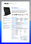
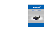
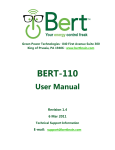
Wireless-G USB Dongle
User’s Manual
Table of Contents
1. Introduction
1.1The Wireless-G USB Dongle
1.2 Key Feature
2. Planning Your Wireless Network
2.1 Network Topology
2.2 Ad-Hoc versus Infrastructure Mode
3. Getting to Know the Wireless-G USB Dongle
4. Installing Driver, Configuration Utility and Hardware for Windows 98SE/ME/2000/XP
5. Using the Configuration Utility in Windows 98SE/ME/2000/XP
5.1 Overview
5.2 Access the Configuration Utility
5.3 Profile
5.4 Create a New Profile
5.5 Link Status
5.6 Site Survey
5.7 Statistics
5.8 Advance
5.9 About
1. Introduction
1.1 The Wireless-G USB Dongle
The Wireless-G USB Dongle installs in most desktop or notebooks and lets you put your
computer almost anywhere in the building, without the cost and hassle of running network cables.
Now you don't have to drill holes in your walls and climb through the attic or cellar to get
connected to the network. Once you're connected, you can keep in touch with your e-mail,
access the Internet, use instant messaging to chat with friends, and share files and other
resources such as printers and network storage with other computers on the network.
The Wireless-G USB Dongle not only connects with Wireless-G networks at an incredible speed
of 54Mbps, it can also interoperate with all the existing 11Mbps Wireless-B (802.11b) products
found in homes, businesses, and public wireless hotspots around the country. And in either mode,
wireless communications are protected by up to 256-bit encryption, so your data stays secure.
1.2 Key Features
◆
◆
◆
◆
◆
◆
Investment Protection: 5 Times Faster and Interoperate with Existing Wireless-B
Equipment
64/128-bit WEP and Advanced WPA/WPA2 (Wi-Fi Protected Access) Encryption Provides
Maximum Wireless Security
Easy to Use and Install with the Help of the Simple Setup Wizard
Compatible with Windows 98SE/ME/2000/XPhe Wireless-
2. Planning Your Wireless Network
2.1 Network Topology
A wireless local area network (WLAN) is exactly like a regular local area network (LAN), except
that each computer in the WLAN uses a wireless device to connect to the network. Computers in
a WLAN share the same frequency channel and SSID, which is an identification name for
wireless devices.
2.2 AD-Hoc versus Infrastructure Mode
An Ad-Hoc wireless LAN is a group of computers, each equipped with one WLAN adapter,
connected as an independent wireless LAN. Computers in a specific Ad-Hoc wireless LAN
must be configured to share the same radio channel.
The adapter provides access to a wired LAN for wireless workstations. An integrated wireless and
wired LAN is called an infrastructure configuration. A group of PC adapter/ card users and an
Access Point can compose a Basic Service Set (BSS). Each wireless node in a BSS can talk to
any computer in the wired LAN infrastructure via the Access Point.
Network Topology
Ad-Hoc versus Infrastructure Mode
3. Getting to Know the Wireless-G USB
Dongle
Wireless-G USB Dongle will install into your PC or Notebook like any other USB adapter using an
existing USB port.
ACT LED Green. The ACT LED will blink when the Dongle transfers or receives data.
4. Installing Driver, Configuration Utility and
Hardware in Windows 98SE/ME/2000/XP
4.1 For Windows 98SE/ME/2000/XP
4.1. 1 Utility Installation
1- Run the Auto Driver/Utility/ Installation
Before connecting the USB adapter, insert the setup CD into the CD-ROM driver. Unless you
have deactivated the auto-run feature of Windows, the screen in Fig 4-1 should appear
automatically. If the screen doesn’t appear automatically, you can access the installation by
clicking the “Start” button and choose “Run”. In the drop-down box type D:\setup.exe (where D:
is the drive letter of your CD-ROM drive). Alternately, double-click “My Computer” and
double-click the “Setup.exe” icon in the folder that appears.
Fig 4-1
2- Click Install Wireless-G USB Dongle Driver and Utility. Click “Next>”. (Fig 4-2)
Fig 4-2
3- In Windows XP, you will see Fig 4-3. Please click “Continue Anyway”. If you use Windows
2000, you will see the Fig 4-4. Please click “Yes”
Fig 4-3
Fig 4-4
4- Click Finish on the Setup Page.(Fig 4-5)
Fig 4-5
4.1. 2 Hardware Installation
1-To install the Wireless-G USB Dongle in a Desktop or Notebook:
‧ Select an available USB port on the notebook or Desktop PC
‧ Insert the Wireless-G USB Dongle into the USB port
2-Windows will automatically detect the Dongle. In Windows XP, you will see Fig 4-6. Please
click “Next” for drivers to automatically load. Fig 4-7 is the screen in Windows 2000. Please
click “Next” for the installation to proceed.
Fig 4-6
Fig 4-7
3- Please reboot the computer after the installation of hardware, drivers and utility.
5. Using the Configuration Utility in
98SE/ME/2000/XP
5.1 Overview
The wireless Configuration Utility can be used to check link information, search for available
wireless networks, or to create profiles that hold different configuration settings.
5.2 Access the Configuration Utility
After installing the adapter, the Configuration Utility icon will appear in your system tray.
Double-click the icon. (Fig 5-1)
Fig 5-1
The utility is divided into six parts: Profile, Link Status, Site Survey, Statistics, Advance, and
About. You should change all your configuration settings for Wireless-G USB Dongle by using
this utility and not with the Network Properties section in Control Panel.
Note: In Windows XP, you should disable the Wireless Zero Configuration service.
A. Right Click My Computer on the desktop and select Manage. (Fig 5-2).
Fig 5-2
B. The Computer Management window comes up. Select Services from the Services and
Applications menu. Scroll down to locate Wireless Zero Configuration service.(Fig 5-3)
Fig 5-3
C. Double Click on Wireless Zero Configuration to go into its properties (Fig 5-4). For Startup
type, choose Disable to disable the Wireless Zero Configuration then click Apply and OK to
make the changes effective. Now you can use our Configuration Utility rather than Windows
XP Wireless Zero Configuration Utility.
Fig 5-4
5.3 Profile
The Profile screen (Fig 5-5) lets you save different configuration profiles for different network
setups. `
Fig 5-5
Profile Name – Connection profile name.
SSID – The unique name used for this profile.
Channel – The channel which the wireless network devices are set on.
Authentication – The Authentication method used in this profile.
Encryption – The Encryption type used for this profile.
Network Type – The Network type used for this profile.
Add- Click the Add button to create a new profile. Please refer to “5.4 Create a New Profile”.
Delete - Click the Delete button to delete a profile.
Edit- Select a profile, and click the Edit button to change an existing profile.
Activate- To activate a specific profile, select the profile, and click the Activate button.
5.4 Create a New Profile
Click the “Add” button on the Profile screen to create a new profile. Fig. 5-6 shows the Add
Profile screen,
Fig 5-6
1- Enter the Profile Name.
2- Fill in the following information.
SSID: Enter the SSID for the wireless network.
Network Type: There are two wireless modes.
(A) Infrastructure - This mode allows wireless and wired networks to communicate through an
access point.
(B) Ad Hoc - This mode allows wireless-equipped computers to communicate directly with
each other. When you select the Ad Hoc mode, the Preamble feature will be
active.
3- Configure Authentication and Security
Fig 5-7
Authentication Type: There are seven type of authentication modes: Open, Shared, LEAP, WPA,
WPA-PSK, WPA2 and WPA2-PSK system.
A. LEAP
Light Extensible Authentication Protocol. It is an EAP authentication type used primarily
in Cisco Aironet WLANs. It encrypts data transmissions using dynamically generated WEP
keys, and supports mutual authentication.
1. Enter Identity
2. Enter Password
3. Click “OK” to save the profile.
B. Open System or Shared Key
1. Select Authentication type: Open System or Shared Key.
2. Select Encrytion: WEP
3. Select the key number that will be used
4. Enter the WEP key: There are several formats to enter the keys.
1. Hexadecimal、64bits:10 Hex characters.
2. Hexadecimal、128bits:32Hex characters.
3. ASCII、40bits:5 ASCII characters.
4. ASCII、128bits:13 ASCII characters.
4. Click “Use 802.1x”, if you want to use it. Refer to section “4- 802.1x Setting”.
5. Click “OK” to save the profile. Please see the Fig 5-8.
Fig 5-8
C. WPA, WPA-PSK, WPA2 or WPA2-PSK
1. Select Authentication type: WPA, WPA-PSK, WPA2 or WPA2-PSK
2. Select Encryption type: TKIP or AES. Please see Fig 5-9
3. Enter WPA Preshared Key, only valid for WPA-PSK and WPA2-PSK. This key
should be between 8 and 32 characters in length.
4. Click “OK” to save the profile. Please see Fig 5-9.
Fig 5-9
4- 802.1x Setting
A. Click “802.1x Setting” button. Please see the Fig 5-10
Fig 5-10
802.1x is an authentication for 『WPA』and 『WPA2』.
802.1x Authentication type:
1.
PEAP: Protected Extensible Authentication Protocol. PEAP securely transports
authentication data by using tunneling between PEAP clients and an authentication server. PEAP
can authenticate wireless LAN clients using only server-side certificates, thus simplifying the
implementation and administration of a secure wireless LAN.
2.
TLS/Smart Card: Transport Layer Security, provides for certificate-based and mutual
authentication of the client and the network. It relies on client-side and server-side certificates to
perform authentication and can be used to dynamically generate user-based and session-based
WEP keys to secure subsequent communications between the WLAN client and the access point.
3.
TTLS: Tunneled Transport Layer Security, this security method provides for
certificate-based, mutual authentication of the client and network through an encrypted channel.
Unlike EAP-TLS, EAP-TTLS requires only server-side certificates.
4.
MD5-Challenge: Message Digest Challenge, is an EAP authentication type that
provides base-level EAP support. It only supports one-way authentication i.e. there is no mutual
authentication of wireless client and the network. It only valid for profile’s authentication type to be
none or shared.
B. If you want to use CA server, please click “CA Server” page. Depending on the EAP in
use, only the server or both the server and client may be authenticated and require a
certificate. Server certificates identify a server, usually an authentication or RADIUS server
to clients. Most EAPs require a certificate issued by a root authority or a trusted
commercial CA. Show as the Fig 5-11
Fig 5-11
1. Certificate issuer: Choose to use server that is the issuer of certificates.
2. Allow intermidiate certificates: It must be in the server certificate chain between the server
certificate and the server specified in the certificate issuer must be field.
3. Server name: Enter the authentication server’s Name..
4. Please click “OK” to save the profile.
5.5 Link Status
The Link Status (Fig 5-12) provides the link information of the Wireless-G USB Dongle.
The Status displays current connection status. If no connection, it will show
Disconnected. Otherwise, the SSID and BSSID will show here.
The Extra Info displays link status and current channel in use.
The Channel field shows the channel which the wireless network devices are currently using.
The Link Speed: Tx(Mbps) field shows the transfer rate in megabits per second.
Rx(Mbps) field shows the receive rate in megabits per second.
The Throughput (Kbps) field is the amount of data moved successfully form one place
to another in a given time period.
The Link Quality field will display a bar indicating percentage, between 0 and 100
percent.
The Signal Strength field will display a bar indicating percentage, between 0 and 100
percent.
The Noise Level displays noise signal strength.
Fig 5-12
5.6 Site Survey
The site survey page displays a list of all infrastructure and ad-hoc wireless networks available for
connection. (Fig 5-13)
Fig 5-13
Information:
SSID – Service Set ID of the Wireless Network.
BSSID – MAC Address of the Wireless AP or Router.
Signal – Signal Strength status.
Channel – The Channel Wireless Network devices are using.
Encryption - Encryption type.
Authentication – Authentication type used.
Network Type - Wireless Network mode
Rescan - Click the Rescan button to search for wireless networks.
Connect – Select one of the networks on the list, and click the Connect button. Please note that
if the wireless network has encryption enabled, you can’t connect. If you want to
connect, you must add a profile in the Profile Tab.
Add Profile – If you click this button, the Profile screen (Figure 5-6) will appear.
5.7 Statistics
The Statistics screen (Shown in Fig 5-14) provides information about the Transmit and Receive
Statistics. You can reset counters if you need, otherwise click OK.
Fig 5-14
5.8 Advance
The Advanced screen (Fig 5-15) allows you to set Wireless Mode, Ad hoc wireless mode, TX
BURST, B/G Protection, Tx Rate and Antenna On/Off.
Fig 5-15
1. Wireless mode: Select wireless mode. 802.11b only and 802.11 b/g mixed mode are
supported.
2. 11B/G Protection: ERP protection mode of 802.11G definition. User can choose from Auto, On,
and Off.
1. Auto: STA will dynamically change as AP announcement.
2. On: Always send frame with protection.
3. Off: Always send frame without protection.
3. Tx Rate: Manually selected the transmit rate. Default is auto.
4. Tx Burst: proprietary frame burst mode which can improve transmission speed.
5. Fast Roaming at: fast to roaming, setup by transmit power.
6. Select Your Country Region Code: support seven difference channel range.
7. CCX2.0: support Cisco Compatible Extensions function:
1.
LEAP turn on CCKM
2.
Enable Radio Measurement: Channel measurement every 0~2000 milliseconds.
8. “Turn off RF” and “Turn on RF” for FAA requirement.
9. If you finished the changes, please click the “Apply” button.
5.9 About
The About screen shows release dates as well as driver/utility versions and the MAC/IP
address of the card.
Fig 5-16