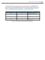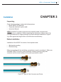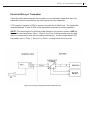
1
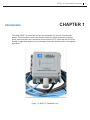
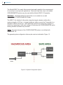
4020LT - A CORROSOMETER®
TRANSMITTER
User Manual
Rohrback Cosasco Systems, Inc.
11841 E. Smith Avenue
Santa Fe Springs, CA 90670
Tel: (562) 949-0123
(800) 635-6898
Fax: (562) 949-3065
www.cosasco.com
P/N 741099rev. -
©2015 Rohrback Cosasco Systems, Inc. All rights reserved.
CORROSOMETER®, CORRATER®, and CORROTEMP®, are registered trademarks of Rohrback Cosasco Systems, Inc.
No part of this manual may be reproduced or transmitted in any form or by any
means, electronic or mechanical, including photocopying and recording, for any
purpose, without the express written permission of Rohrback Cosasco Systems,
Inc.
4020LT-A Corrosometer Transmitter
Table of Contents
Chapter 1 Introduction ............................................................................. 1
Chapter 2 Specification ..................................................................................5
Chapter 3 Installation .....................................................................................7
Unpacking...................................................................................................7
Before Installation. ......................................................................................7
Mechanical Mounting of Transmitter ......................................................... 8
Electrical Wiring of Transmitter ................................................................... 9
Chapter 4 Operation ................................................................................ 11
Metal Loss From 4-20 mA Signal ............................................................11
Corrosion Rate Calculation. .....................................................................11
Probe Spans. ............................................................................................15
Chapter 5 Maintenance ........................................................................... 17
Appendix A ................................................................................................ 19
CORROSOMETER Theory ..................................................................... 19
Appendix B ................................................................................................ 25
Requirements for Intrinsic Safety Operation .............................................25
i
ii
Table of Contents
4020LT-A Corrosometer Transmitter
Figures and Drawings
Figure
Page
1.1
4020LT-A Transmitter Unit ...................................................1
1.2
System Configuration Options ............................................2
1.3
Instrument Type/Probe Type Compatibility ..........................3
3.1
Types of Cable Connectors and Probes..........................7
3.2
Mounting Dimensions ...........................................................8
3.3
Wiring Configurations with Safety Barriers ........................9
4.1
CORROSOMETER® Probe Types and Spans ...................15
iii
iv
Table of Contents
4020LT-A Corrosometer Transmitter
CHAPTER 1
Introduction
The Model 4020LT-A transmitter is a two-wire transmitter for use with Corrosometer
probes. This transmitter is well suited for plant locations, widely separated monitoring
points, and connection into a distributed control system (DCS). (Note that the DCS must
be able to graph data against time and compute metal loss corrosion rates from supplied
algorithms.)
Figure 1.1 4020LT-A Transmitter Unit
1
2
Introduction
The Model 4020LT-A is easily field mounted and readily applied to the measurement
of corrosivity in most process applications. Most wire loop, tube, strip or all welded
CORROSOMETER probes may be used with the Model 4020LT-A Transmitter.
WARNING! The Model 4020LT-A transmitter is not suitable for use with
CORROTEMP CORROSOMETER Probes
The 4020LT-A is attached to the probe using the integral extension cable with a
maximum length of 100 feet. A single twisted pair cable connects the Transmitter to a
standard 4-20mA current loop. The Transmitter controls loop current as a function of
metal loss, beginning at 4mA, and ending at 20mA when the CORROSOMETER probe
sensing element has been fully corroded.
NOTE: The check element of the CORROSOMETER probe is not utilized with
Model 4020LT-A.
The general system configuration that may be used are indicated in Figure 1.2
Figure 1.2 System Configuration Options
4020LT-A Corrosometer Transmitter
The Model 4020LT-A is compatible with any Rohrback Cosasco CORROSOMETER
probe type, but is furnished specifically for each of the three basic probe types from the
factory. The compatibility is listed in Figure 1.3. It is field convertible from one type to
another by selecting a probe type with the rotary switch on the front panel.
Transmitter Suffix
-W-T-
Probe Type
A
B
Element Type Applicable
W40, W45, W60, W80
T4, T8, S20, S40, S60
S
C
S4, S8, S10,
-SP-
D
T10, T20, T50
Figure 1.3 Instrument Type/Probe Type Compatibility
3
4020LT-A Corrosometer Transmitter
CHAPTER 2
Specification
Transmitter Model 4020LT-A
•
Enclosure NEMA 4X, IP66 or Stainless Steel (316L), IP66
•
Weight 4 lbs. (1.8 Kg)
•
Dimensions 8.00”H x 6.25”W x 4.25”D (203mm x 165mm x 108mm)
•
Probe Cable Length 5ft. Standard, 100ft. Maximum
•
Hazardous Area Certifications
USA/Canada
CSA Canada
Ex ib IIC T4 Gb, Tamb= -40°C to +80°C
CSA US
Class I, Zone 1, AEx ib IIC T4 Gb, Tamb= -40°C to +80°C
Sira
ATEX Ex ib IIC T4 Gb, Tamb= -40°C to +80°C
Sira
IEC Ex ib IIC T4 Gb, Tamb= -40°C to +80°C
Europe
IECEx
Hazardous Area Certification Notes:
Requires the use of a galvanically isolated safety barrier if probe or transmitter is
in a Class 1 Division 2 area, Zone 1, or Zone 2.
Complies with all applicable EU Product Directives: EMC Directive 9/336/EEC
ATEX
Complies with all applicable EU Product Directives: ATEX Directive 94/9/EC
•
Supply Voltage Range 10-30 VDC at 20 mA
•
Output 4-20 mA into maximum safe area load of 600 ohms with safety barrier
•
Resolution ± 0.1%
•
Ambient Temperature Range -40°C (-40°F) to +80°C (176°F)
5
6
Specification
4020LT-A Corrosometer Transmitter
CHAPTER 3
Installation
Unpacking
Check that the package contains the following items:
• Model 4020LT-A Transmitter
• Test probe attached to probe cable
• Instruction Manual
NOTE: All 4020LT-A system components are carefully tested, inspected and
packaged prior to shipment. Before unpacking the instruments, please inspect the
packaged materials for shipping damage and retain damaged materials to support
any claim against the freight carrier should this become necessary.
Before Installation
Installation of the 4020LT-A consists of two separate tasks:
•
•
Mechanical mounting
Electrical wiring
Before proceeding with the installation, several items must be considered. Make sure
the Model 4020LT-A has the correct Rohrback Cosasco Systems type probe
connector and the correct setting for the probe type selector switch.
Figure 3.1 Types of Cable Connectors and Probes
7
8
Installation
The transmitter should be mounted close enough to the probe to allow the use of
the 60-inch extension cable supplied. For mounting of the transmitter or probe in
a hazardous area the correct galvanically isolated safety barrier and instructions
of the intrinsic safety certification must be followed.
NOTE: Transmitters are available with longer cables up to a maximum of 100 ft.
Mechanical Mounting of Transmitter
The Model 4020LT-A Transmitter should be located within 48 inches of the
CORROSOMETER probe to be monitored. The standard cable is 60 inches long and
the extension cable is 1200 inches long, but it is preferable to allow a service loop of
approximately 12 inches to the probe.
Figure 3.2 Mounting Dimensions
4020LT-A Corrosometer Transmitter
Electrical Wiring of Transmitter
If both the probe and transmitter are located in a non-electrically hazardous area, the
transmitter may be connected as any other typical two wire transmitter.
A DC supply of typically 24 VDC is required to power the 4-20mA loop. The transmitter
requires between 10 and 30 VDC at the transmitter terminals for correct operation.
NOTE: If the environment for both the probe element in the process stream, AND the
transmitter are classified as Class 1, Division 2 or Zone 2 the transmitter may be used
without a safety barrier (see intrinsic safety certifications). If either probe element OR
transmitter are in a Class 1, Division 2 or Zone 1 a safety barrier must be used.
Figure 3.3 Wiring Configurations With Safety Barriers
9
10
Installation
4020LT-A Corrosometer Transmitter
Operation
CHAPTER 4
The output from a model 4020LT-A transmitter is a 4-20mA signal that corresponds
linearly to the range of zero to the probe span.
WARNING! This linear output is different from the earlier model 4020 transmitter,
which had a non-linear characteristic. If using the 4020LT-A to replace a model 4020
the conversion formula for the corrosion data must be modified.
Metal Loss From 4-20mA Signal
To convert the 4-20mA signal into metal loss the conversion formula is as follows:
It is advisable to record the metal loss typically every five minutes and generate a graph
of metal loss against time. Visual display of the data is very useful to check general
trends and the significance of any signal noise. It is also helpful in determining the filter
factor for the corrosion rate algorithm as detailed in the next section.
Corrosion Rate Calculation
For Distributed Control Systems (DCS) we recommend a corrosion rate algorithm
based on linear regression (the best straight line), with an adjustable filter factor. The
adjustable filter factor is obtained by varying the number (or time period) of readings
(m in the formula) over which the liner regression is applied. Readings are best taken
every five minutes.
11
14 Operation
The time period over which the data should be computed is 1 to 5 days, with the ability
to adjust this, preferably on an individual probe channel basis.
(1)
where,
(2)
and,
y = value of metal loss numbers, corresponding to x time base values
x = the time base values
m = the number of points used for the regression
Depending on the units chosen for x and y, the corrosion rate may need to be converted
to the rate units required.
As an example if y is in units of mils, as determined from the formula in the Metal Loss
from 4-20 mA signal section, and x is in units of days from some nominal origin. Using
a time base of 3 days of data for calculation of rate (i.e. 3 x 24 x 12 = 864 data points)
the corrosion rate from equations (1) and (2) would be in units of mils/day. This could
normally be converted to mils/year by multiplying by 365.
In setting up the algorithm the time period of 3 days in the example should be adjustable
from 1 to 5 days to provide filtering as necessary to minimize noise yet give adequate
sensitivity to upsets. The shorter the time period, the more sensitive but noisier will be
the rate calculation. The longer the time period, the less sensitive but quieter will be the
rate calculation.
4020LT-A Corrosometer Transmitter
Probe Spans
The following table indicates the probe spans for the various probe types available
CORROSOMETER PROBE ELEMENT
TYPE
Strip Loop S4
Flush Element S4*
Atmospheric Element S4*
Strip Loop S8
Tube Loop T4
C
B
D
C
B
Flush Element S8*
Atmospheric Element S8*
Tube Loop T8
Flush Element S10*
Cylindrical Element T10
Flush Element S20*
Cylindrical Element T20
Wire Loop Element W40
Wire Loop Element W45
Flush Element S40*
Wire Loop Element W80
Cylindrical Element T50
B
D
B
B
D
B
D
A
A
B
A
D
mils
1.0
2.0
SPAN
mm
0.025
0.051
m
25
51
4.0
0.102
102
5.0
0.127
127
10.0
0.254
254
11.25
20.0
0.285
0.508
286
508
25.0
0.635
635
Figure 4.1 CORROSOMETER Probe Types and Spans
15
16 Operation
4020LT-A Corrosometer Transmitter
Maintenance
17
CHAPTER 5
The Model 4020LT-A Transmitter should require little maintenance. Normal probe
replacement is required in order to maintain continuous corrosion monitoring at a site.
All probes have a certain life based on their geometry and amount of corrosion they are
exposed to. A probe replacement schedule should be established with a criterion such
as 7/8 of probe life (875 span divisions) to time change out.
As a reminder, proper probe selection should be based on closely matching probe span
to mpy corrosion rate for optimum instrument accuracy.
During probe replacement, all connections, such as the connectors at the probe, should
be environmentally protected and checked for good electrical conduction. Under normal
conditions the Transmitter should not require recalibration when replacing identical
probes. It is recommended as a good procedure that the current loop power source be
powered down during probe change out.
WARNING! For reasons of maintaining the intrinsic safety certifications it is important
that any repairs be carried out by RCS or its authorized agent to maintain the
certification of the instrument.
The Model 4021L Receiver requires no maintenance. If a problem is suspected with
the probe or transmitter, use the test probe provided with the transmitter to test the loop.
The test probe is marked with the loop current in mA that this should provide in the 4-20
mA loop. This signal may be converted to check the display on the receiver if applicable
18 Maintenance
4020LT-A Corrosometer Transmitter
19
APPENDIX A
CORROSOMETER THEORY
CORROSOMETER Systems are based on the electrical resistance method of corrosion
monitoring pioneered by Rohrback in the 1950’s and 1960’s. CORROSOMETER
probes are basically “electrical coupons.” They determine the loss of metal from the
probe by measuring the change in its resistance. Because of the very low resistances
involved, very sensitive monitoring circuits are used in CORROSOMETER instruments
to measure the change in probe resistance compared to a protected reference element
resistance series-connected to the corroding measurement element. A “check” element
is also included and is protected from the process along with the reference element.
The ratio of check to reference resistance should remain constant. If it doesn’t, this
indicates that degradation of the reference element may be occurring and that metal
loss readings obtained from the probe are questionable. A simplified diagram of a
typical electrical resistance monitoring circuit is shown in Figure 1.
Figure 1
20 Corrosometer Theory
As with coupons, CORROSOMETER probes must be allowed to corrode for a period
of time before accurate corrosion rate measurements can be made. The actual length
of time required depends upon the corrosion rate--the higher the rate, the shorter the
time required, and vice-versa. CORROSOMETER probes are available in a variety of
styles and with useful probe life (“span”) ranging from 2-25 mils, in styles commonly
used in process piping systems. Instrumentation to measure electrical resistance
probes divides the probe span into l000 “divisions.” A probe with a 2 mil span is
therefore theoretically capable of measuring thickness changes of 0.002 mils. In
practice, however, we recommend that a change in indicated metal loss of l0 divisions
be required before the data is used to calculate corrosion rate. Indications of an upward
or downward trend can be obtained with as little as a 4-division change, but care must
be exercised in interpreting such small changes because other factors (e.g. temperature
changes) can also be responsible. The actual time required to produce meaningful
corrosion rate information with common probe spans at different corrosion rates is
shown in Figure 2 and summarized in Table 1.
Figure 2
4020LT-A Corrosometer Transmitter
Corrosion Probe Span (mils)
Rate
2
4
(mpy)
0.1
73 days
5 months
0.5
15 days
29 days
1.0
7 days
15 days
5.0
35 hours
3 days
10
18 hours
35 hours
25
7 hours
14 hours
50
4 hours
7 hours
75
140 mins
5 hours
100
105 mins
4 hours
5
10
6 months
37 days
18 days
4 days
2 days
18 hours
9 hours
6 hours
5 hours
20
25
12 months 24 months 30 months
73 days
5 months 6 months
36 days
73 days
3 months
7 days
15 days
18 days
4 days
7 days
9 days
35 hours
3 days
4 days
18 hours
35 hours
2 days
12 hours
23 hours
29 hours
9 hours
18 hours
22 hours
Table 1
Elapsed Time* To:
Early Trend
Indication
(4 Div.)
1.6 hour
Meaningful
Rate Data
(10 Div.)
4.0 hour
End of Useful
Probe Life
(1000 Div.)
17 days
4.0 hour
10.0 hour
1.4 months
9.6 hour
1 day
3.3 months
18.0 hour
1.8 days
6.0 months
1.1 days
2.7 days
9.0 months
1.5 days
3.7 days
12.0 months
1.8 days
4.6 days
15.0 months
2.2 days
5.5 days
18.0 months
2.9 days
7.3 days
24.0 months
* All data shown to two significant digits only.
Table 2
Corrosion
Rate*
with 10 mil
Span Probe
220 mpy
(5.6 mm/y)
88 mpy
(2.2 mm/y)
37 mpy
(0.94 mm/y)
20 mpy
(0.51 mm/y)
13 mpy
(0.33 mm/y)
10 mpy
(0.25 mm/y)
8 mpy
(0.20 mm/y)
6.7 mpy
(0.17 mm/y)
5 mpy
(0.13 mm/y)
21
22 Corrosometer Theory
From Table 1, it would appear desirable to always choose probes with the lowest span
available in order to get the greatest sensitivity. However, the more sensitive the
probe, the faster the entire probe span will corrode away and require a new probe to be
installed.
Table 2 illustrates this relationship.
It is our experience that the objectives of most monitoring programs can be achieved
cost-efficiently by selecting CORROSOMETER probes which will reach the end of their
useful life in 6 - 9 months at the expected corrosion rate. Unlike a monthly coupon
replacement program, this electrical resistance probe will continuously produce data
that verifies that the average corrosion rate over the previous 2-3 days is still at the
originally-expected (design) rate. If the corrosion rate increases to twice the design
rate, meaningful data to permit the new rate to be calculated will be available in a day
and a half. Conversely, if the actual corrosion rate is below design, a longer period is
required before meaningful data are available to calculate the new rate.
CORROSOMETER probe elements are available in a variety of styles. A selection of
the available styles is shown in Figure 3. Wire, tube, and strip-loop styles all have a
loop of metal exposed to the process. The loop protrudes from the end of the probe
body through either a hermetic glass seal or a Teflon/ceramic, Teflon/epoxy or epoxy
seal/packing system. Choice of materials is dependent upon stream composition,
process conditions and performance requirements. Cylindrical elements utilize
specially-made, thin-wall tubing as the measurement element. Cylindrical probes are
generally “all-metal;” i.e., there is no other material exposed to the process. There are,
however, also some cylindrical probes available which join the probe body at a hermetic
glass seal. A variety of flush-mounted probes are also available; so-called because
the measuring element is mounted parallel to the flow stream, flush with the inside pipe
wall.
STRIP LOOP
TUBE LOOP
WIRE LOOP
CYLINDRICAL
ATMOSPHERIC
Figure 3
FLUSH END VIEW
FLUSH END VIEW
4020LT-A Corrosometer Transmitter
CORROSOMETER monitoring systems can be applied to all processes. However,
some types of CORROSOMETER probes are better suited to the requirements of
particular applications than others.
Different styles of CORROSOMETER probes are affected to different degrees by pitting
attack. Figure 4 shows the results of pitting attack on a wire loop probe. Although
the remaining wire thickness shows that only 30% or so of the probe span has been
consumed, the probe is obviously out of service. Cylindrical elements on the other
hand, are affected to a much lesser degree by pitting because of the much larger
circumference of the measuring element. Wire loop and tube loop elements also have a
tendency to be electrically shorted by a bridge of iron sulfide corrosion product. This is
especially prevalent in low-velocity streams over an extended period. The effect of such
bridging is to reduce the measured metal loss of the probe, creating a misleadingly low
corrosion rate. Cylindrical probes demonstrate more resistance to iron-sulfide bridging
due to their construction and lower inherent resistance per unit length, thus minimizing
the effect of the shunt resistance. Where pitting or substantial FexSy deposition are
expected to be problems, cylindrical probes should be chosen wherever possible over
loop-style probes.
Figure 4
23
24 Corrosometer Theory
Most cylindrical probes are of all-welded construction in order to eliminate the need
for sealing metal elements to non-metallic glass, epoxy or ceramic. This all-welded
construction gives the probe superior resistance to leaking. Probes with higher
temperature ratings can also be constructed in the all-welded style. A drawback to the
all-welded style is that the element is electrically connected to the pipe wall which can,
in certain conditions, interfere with the corrosion reaction on the probe. Also, because
cylindrical probes are welded, in some conditions preferential corrosion can occur in the
heat-affected zones near the weld.
Flush probe elements are thin, flat metal sections embedded in epoxy or a hermetic
glass seal inside a metal probe body. Flush probes also experience certain
characteristic problems, most notably: lack of adhesion of the metal element to the
epoxy, cracking of glass seals due to differential expansion and erosion of the epoxy
or glass due to high velocities, abrasive materials in the flow stream or both. Flush
CORROSOMETER probes mounted on the bottom of the line have been shown to
provide good results in a sour gas gathering system.
Because the measurement element is part of the primary pressure seal, and because
it’s designed to corrode, CORROSOMETER probes have a reduced resistance to
leaking after prolonged exposure. Once the measurement element has corroded
through, the internals of the probe body are exposed to the process fluid. Although
materials are chosen in part for their strength and lack of permeability, it is our
experience that process fluids will permeate throughout the probe packing material.
For this reason, quality probes are constructed of corrosion-resistant body materials
and include a secondary pressure seal, often consisting of a hermetic glass-sealed
connector. Other back-up seals are utilized in special cases, especially where process
fluids will attack glass (e.g. hydrofluoric acid service). Please contact the factory if you
have any questions about the compatibility of probe materials with your application.
The reference and check elements are protected from the process to which the
measurement element is directly exposed. Temperature changes in the process
will, therefore, affect the measure element before the reference and check elements.
Because of the very low resistances involved, these changes can significantly affect the
metal loss readings. CORROSOMETER probes incorporate special design features
to minimize the thermal resistance of the materials insulating the reference and check
elements from the process. It should also be noted that cylindrical probes are inherently
better able to react to temperature changes due to location of the reference and check
elements concentrically inside the measure element.
4020LT-A Corrosometer Transmitter
Requirements for Intrinsic
Safety Operation
25
APPENDIX B
To meet the requirements of the certifying authorities for the intrinsic safety certifications
under which the equipment is operated, it is important that the requirements of
the certifications documents and installation practices are followed. The following
certification documents provide this information.
WARNING! The transmitter has certifications for use with a safety barrier. In
general, the process stream into which the CORROSOMETER probe is
installed will determine if a safety barrier is required. If this process stream is
classified as Class 1 Division 2, or Zone 1 by the jurisdiction of the applicable
authority, then a safety barrier MUST BE USED.
26 Corrosometer Theory
4020LT-A Corrosometer Transmitter
27
28 Requirements for Intrinsic Safety Operation
4020LT-A Corrosometer Transmitter
29
30 Requirements for Intrinsic Safety Operation
4020LT-A Corrosometer Transmitter
31
32 Requirements for Intrinsic Safety Operation
4020LT-A Corrosometer Transmitter
33