1
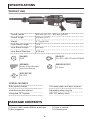
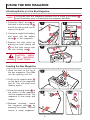
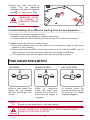
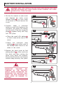
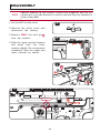
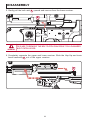
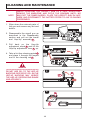
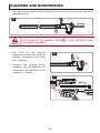
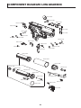
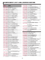
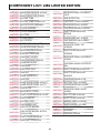
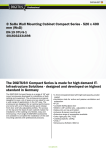
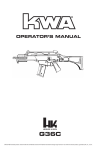
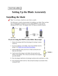
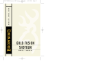
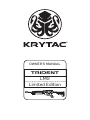
®
OWNER’S MANUAL
TRIDENT
LMG
Limited Edition
SEMI
SAFE
AUTO
TABLE OF CONTENTS
Safety Rules ...................................................................................................... 2
Technical Specifications..................................................................................... 4
Package Contents.............................................................................................. 4
Using the Magazine............................................................................................ 5
Fire Selector Switch........................................................................................... 6
Battery Installation.............................................................................................. 7
Hop-Up System.................................................................................................. 8
Clearing Jammed BBs........................................................................................ 9
Disassembly..................................................................................................... 10
Assembly.......................................................................................................... 12
Cleaning and Maintenance............................................................................... 13
Operating Under Harsh Conditions.................................................................. 15
Contact Information.......................................................................................... 15
Trouble Shooting Guide.................................................................................... 16
Component Diagrams and Lists....................................................................... 17
1
SAFETY RULES
Please read the entire KRYTAC manual before operating the airsoft gun. This manual
covers important safety, operational, and maintenance topics. It is important that the
user reads and understands the manual in order to safely handle and operate the airsoft gun. Failure to follow the safety guidelines and/or operational instructions in this
manual may result in serious personal injury or damage to the airsoft gun.
Safety Guidelines
EYE PROTECTION
Always wear eye protection while shooting, operating, and maintaining your airsoft guns.
FIREARM SAFETY RULES
Always assume that the airsoft gun is loaded. Never assume the chamber is
empty based on memory or from someone else’s word. An airsoft gun can still fire
with the magazine removed.
KEEP YOUR FINGER OFF THE TRIGGER
Remove your finger from the inside of the trigger guard until your sights are aligned
on target and you are ready to fire.
MUZZLE CONTROL
Always keep the muzzle of the airsoft gun pointed in a safe direction. Never point the
airsoft gun towards anything you do not intend to shoot.
KNOW YOUR TARGET AND ITS SURROUNDINGS (SAFETY DISTANCE)
Take note of objects in front of and beyond your target. Airsoft guns can shoot up
to and beyond 150 feet and may travel further than intended without an adequate
backstop. Never shoot an airsoft gun directly at targets such as rocks, glass, water,
or other hard surfaces that may ricochet BBs in unpredictable directions.
SAFETY IS YOUR RESPONSIBILITY
WARNING
The KRYTAC airsoft gun is designed and manufactured to KRYTAC’s high standards.
It was carefully inspected before it was packaged and shipped from our factory. It is
the sole responsibility of the user for its safe use and handling. This airsoft gun is safe
unless handled irresponsibly or misused.
BEWARE OF BARREL OBSTRUCTIONS
Ensure that the barrel of your airsoft gun is free and clear of any obstructions prior to
firing the airsoft gun. Failure to do so may cause a malfunction, and in some cases
damage the airsoft gun.
KEEP THE SAFETY ON
Keep the fire selector set to safe until your sights are aligned on target and you are
ready to fire.
2
SAFETY RULES
FAILURE TO FIRE
If the airsoft gun fails to fire, misfires, or malfunctions, do not look into/down the
barrel of the airsoft gun. BBs can jam in the chamber and can launch suddenly while
under pressure causing serious injury.
MAINTAIN YOUR AIRSOFT GUN PROPERLY
Maintaining your airsoft gun as outlined in the manual ensures that your airsoft
gun will be safe to shoot and perform to its designed specifications. Alterations,
modifications, or adjustments may damage your airsoft gun, making it unsafe to
shoot and/or voiding all warranty claims.
STORAGE AND TRANSPORT
Keep the fire selector on the airsoft gun set to safe, with the magazine and battery
removed when storing your airsoft gun. Always store your airsoft gun in a safe place
and out of the reach of children. When transporting your airsoft gun make sure that it
is in a designated airsoft gun case. Never brandish your airsoft gun in public.
WARNING
IT IS YOUR RESPONSIBILITY TO SAFELY STORE AND
TRANSPORT YOUR AIRSOFT GUN.
ORANGE TIP
Any alteration of the coloration or markings required by state and/or federal law may
be deemed illegal in a court of law. All risks and responsibility of any alteration to the
product will be assumed by the operators, owners and/or user of the product.
WARNING
THE ORANGE TIP DOES NOT DISTINGUISH YOUR AIRSOFT
GUN AS A TOY, ALWAYS TREAT YOUR AIRSOFT GUN AS IF IT
IS A REAL FIREARM.
HAZARDS OF BEING MISTAKEN FOR A REAL FIREARM
Due to the nature and design of some airsoft guns, they may be mistaken as a real
firearm. It is strongly advised to operate an airsoft gun in the safety and privacy of
your own home, or at a legally sanctioned location or game field. Police, Peace
Officers, and Law Enforcement Officers are trained to treat objects that resemble
a firearm as one. In the event that you are approached by a Law Enforcement
Official, completely comply with their instructions. Never point an airsoft gun at a
Law Enforcement Official. Confrontation with a Law Enforcement Official may result
in serious injury or death.
ALCOHOL, MEDICATIONS AND DRUGS
Do not handle or operate your airsoft gun while under the influence of alcohol,
medication, or drugs that may impair judgment.
3
SPECIFICATIONS
TRIDENT LMG
Overall Length
855 mm (31.70”) - 935 mm (36.80”)
Overall Height
200 mm (7.87”)
Weight
3.7 kg (8.2 lb)
Outer Barrel Length
14.5”
Inner Barrel Length
416 mm
Inner Barrel Diameter
6.05 mm
CALIBER
6 MM
VELOCITY
115+ MPS / 380+ FPS with 0.20g BB
MECHBOX
Krytac Trident Mechbox
with 8 mm Bearing
ENERGY OUTPUT
1.3 Joules
RATE OF FIRE
20+ RPS
SPECIAL FEATURES
Easy spring change
Full metal upper and lower receiver
Ambidextrous fire selector
Adjustable rotary Hop-Up
Integrated FET system
KRYTAC battery stock
PACKAGE CONTENTS
[1] Trident LMG Limited Edition airsoft gun
[1] Box magazine
4
[1] User’s manual
[1] Cleaning rod
USING THE BOX MAGAZINE
Attaching Battery to the Box Magazine
NOTE
The Krytac LMG Box Magazine operates from a single 9 volt battery A .
Install the battery prior to loading the box magazine with BBs.
1.Follow the “Open” arrow B on
the back to the locking tab C
and lift the tab up and over to
remove the panel.
1
2
9V
2.Connect a single 9 volt battery
and place into the battery
cavity D in the magazine.
3.
Replace the side panel by
placing the front locking tab
E on first then secure with
the last locking tab F .
A
C
D
B
3
E
F
DISCONNECT THE
BATTERY WHEN
THE MAGAZINE
WARNING
IS NOT IN USE
Loading the Box Magazine
1.Open the door on the top of
the box magazine. Pour BBs
into the opening until full.
1
2.Push up the reserve latch A
on the back of the magazine
and tilt. This will allow more
loading space
OP
EN
3.Press the loading button B at
the bottom of the magazine
until the magazine clicks. The
magazine is now ready and
loaded.
2
OP
EN
4.
Between shooting, rewind
the magazine spring C by
pressing the button. This will
ensure a ready magazine.
A
3-4
B
C
5
5.
When the main reservoir is
empty, turn the magazine
sideways and open the reserve
latch D to load more BBs.
5
D
WARNING
OP
E
N
ALWAYS UNLOAD
MAGAZINE PRIOR
TO STORAGE TO
PRESERVE SPRING
LIFE.
Troubleshooting: If no BBs are feeding from the box magazine
OP
EN
1.No noise from the box magazine motor.
a.Check to see that the battery is properly connected.
b.Check to ensure that the battery still has power. If not replace the battery.
2.Makes a noise but does not seem to feed.
a.Press the winding button on the bottom of the magazine again to add more
tension to the follower.
b.Ensure that there are BB’s in the main reservoir. If not, load more BB’s into the
main reservoir from the secondary reservoir or through the BB door.
c.The magazine may have an obstruction and will require servicing.
FIRE SELECTOR SWITCH
SAFE MODE
SEMI-AUTO MODE
SEMI
SAFE
SEMI
AUTO
When in safe mode, the
trigger will not engage
and the airsoft gun will
not fire.
SAFETY
TIP
WARNING
FULL-AUTO MODE
SAFE
SEMI
AUTO
While
in
semi-auto
mode, the airsoft gun
will only fire one shot for
each time the trigger is
engaged.
SAFE
AUTO
In full-auto mode, the
gun will continuously fire
as long as the trigger
remains engaged.
It is advised when you are not ready to fire, keep the fire selector
switch on the airsoft gun in the safe position.
DO NOT ENGAGE THE TRIGGER WHILE SWITCHING BETWEEN
MODES ON THE FIRE SELECTOR.
6
BATTERY INSTALLATION
WARNING
ENSURE THAT THE STOCK IS IN THE FULLY COLLAPSED POSITION
BEFORE OPENING THE STOCK COVER. DO NOT REMOVE THE STOCK
COMPLETELY FROM THE GUN.
1
1.Set the fire selector to safe mode
and depress the stock cover
release button A on both sides
of the stock to lift and remove the
cover.
SEMI
SAFE
AUTO
A
2.
Connect either a nunchuck
battery or small LiPo battery to the
connector and place the battery
into the stock. Push the connector
plugs B together firmly until they
lock into place.
2
B
a.Place the small LiPo battery C
so that it rests at the rear of the
stock.
2a
b.
Place the nunchuck style
batteries D down either side of
the battery tubes found on the
sides of the stock.
C
3.Replace the stock cover by first
placing the tab E of the cover into
the stock and then rocking the
stock cover down into position.
Ensure that the stock cover release
buttons snap securely into place.
2b
D
3
WARNING
EXCESSIVE
PULLING
OR
TUGGING OF THE BATTERY
WIRES WHEN INSERTING OR
REMOVING THE BATTERY CAN
CAUSE THE FUSE HOUSING TO
COME LOOSE OR DAMAGE TO
THE GUN.
SEMI
SAFE
AUTO
7
E
HOP-UP SYSTEM
The advanced KRYTAC rotary Hop-Up unit is a standard feature in the Trident series
AEGs. Proper adjustment of the Hop-Up will allow the AEGs to fire in a variety of
shooting environments to obtain optimal BB trajectory.
Hop-Up Adjustment
1.
Pull the charging handle A
downward then rearward. Hold
charging handle in position to
access the Hop-Up adjustment
dial B .
1
2.Turn the dial up or down, an
audible click will confirm each
adjustment.
A
3.Increasing the number on the
dial will increase the amount of
Hop-Up on the BB. Decreasing
the number will lower the amount
of Hop-Up on the BB.
B
2
MANUFACTURED IN TAIWAN
FOR TRAINING USE ONLY
MANUFACTURED IN TAIWAN
FOR TRAINING USE ONLY
8
HOP-UP SYSTEM
Excessive Hop-Up
Airsoft BB travels in an extreme upward trajectory. Decrease the Hop-Up.
Ideal Hop-Up
Airsoft BB travels in a long, horizontal flight path.
Insufficient Hop-Up
Airsoft BB travels a short distance in a downward trajectory. Increase the Hop-Up.
Excessive
Ideal
Insufficient
CLEARING JAMMED BBS
1.Disassemble the airsoft gun and remove the inner barrel assembly A . (see pg11
for disassembly instruction).
2.Lift the Hop-up lever B from the inner barrel assembly (refer to step 3 of pg13).
3.Take the cleaning rod C and insert the unjamming side from the front of the barrel
through to the rear to clear out the jammed BB.
4.Look through the barrel to ensure that it is cleared.
5.Reassemble the airsoft gun. (see pg12 for assembly instruction).
C
A
NOTE
B
C
Jammed BB
It is important to remember that all KRYTAC airsoft guns are made with
high quality precision barrels, use only new, quality airsoft BBs. Never
use recycled or low quality airsoft BBs, doing so may cause excessive
jamming. In most cases, it can severely damage the internal gearbox
and/or Hop-Up and inner barrel.
9
DISASSEMBLY
NOTE
Before opening up the receiver, remove the magazine and fire the
airsoft gun in a safe direction to ensure that the Hop-Up chamber is
clear of any BBs.
1.Set the AEG to safe mode.
1
SEMI
2.
Remove the stock cover and
disconnect the battery.
SAFE
3.Remove ONLY the front pin A
from the receiver.
AUTO
2
4.Slide the upper receiver forward
and away from the lower
receiver slightly. Do not seperate
completely. Align the upper and
lower receiver as shown.
3
A
A
4
Align here
SEMI
TM
SAFE
TM
10
AUTO
DISASSEMBLY
5.Gently pull the bolt catch B upward and remove from the lower receiver.
5
B
SEMI
TM
SAFE
AUTO
TM
WARNING
FAILURE TO REMOVE THE BOLT CATCH CAN RESULT IN A DAMAGED
BOLT CATCH LEVER.
6.Completely seperate the upper and lower receiver. Slide the Hop-Up and inner
barrel assembly C out of the upper receiver.
6
C
SEMI
TM
SAFE
TM
11
AUTO
ASSEMBLY
1.Insert the Hop-Up and inner barrel
assembly into the upper receiver.
1
2.Slide the upper receiver back onto
the lower receiver. Stop when
receivers are aligned as shown.
3.Insert bolt catch A into the lower
receiver and press firmly into place.
2
4.Carefully slide the upper receiver
fully onto the lower receiver.
Align here
5.Reinstall and secure the front body
pin.
SEMI
TM
SAFE
AUTO
TM
3
A
S
SAFE
4
SEMI
SAFE
5
12
AUTO
CLEANING AND MAINTENANCE
NOTE
WHILE POINTING THE AIRSOFT GUN IN A SAFE DIRECTION,
REMOVE THE MAGAZINE AND CYCLE THE GEARBOX UNTIL NO
BBS EXIT THE INNER BARREL. PLACE THE AIRSOFT GUN IN SAFE
MODE AND DISCONNECT THE BATTERY PRIOR TO ANY CLEANING
PROCEDURES.
1. Wipe down the external parts of
the gun and remove any dirt and
debris.
1
2. Disassemble the airsoft gun as
described in the Disassembly
section and pull out the barrel
and Hop-Up assembly A .
SEMI
TM
SAFE
AUTO
TM
3.Pull back on the Hop-Up
adjustment wheel B and lift the
Hop-Up adjustment lever C up.
2
A
4. Take a lint-free cleaning patch D
and place it through the looped
end of the cleaning rod E .
SEMI
TM
SAFE
AUTO
TM
WARNING
3
DO NOT ADD OIL TO THE HOP-UP
BUCKING. EXCESSIVE OIL ON THE
HOP-UP BUCKING MAY NEGATE
THE HOP-UP, DECREASING RANGE
AND ACCURACY.
C
4
E
D
13
B
CLEANING AND MAINTENANCE
5. Run the cleaning rod through the barrel from back to front (in the same direction
that BBs travel).
5
F
WARNING
KEEP TRACK OF THE BARREL SPRING F , IT CAN SEPARATE FROM
THE BARREL ASSEMBLY.
6.
Pull back on the Hop-Up
adjustment wheel and lower the
Hop-Up adjustment lever back
into position.
6
7.Reinsert the Hop-Up barrel
assembly into the receiver and
reassemble as described in the
Assembly section.
7
SEMI
TM
SAFE
TM
14
AUTO
OPERATING UNDER HARSH CONDITIONS
When operating under harsh conditions, special maintenance may be required to
match the climate conditions of a specific operational area.
Dust and Sand
In harsh dusty or sandy environments, excessive debris can cause malfunctions and/
or excessive wear on parts. Keep the gun covered and protected while not in use.
When performing maintenance, use lubrication sparingly as it tends to attract dirt
and other particles. After use in a dusty or sandy area, always field strip the gun, as
outlined in the Disassembly section, cleaning all the areas that can be reached with
a soft, clean, lint-free cloth.
Heavy Rain
Never submerge or expose your gun to extremely wet environments. Exposure to
such conditions may cause electrical failure and fluid to build-up inside the gearbox.
Dry completely with a clean, lint-free cloth and clean inner barrel when necessary.
CONTACT INFORMATION
For additional troubleshooting, information, or questions regarding KRYTAC
customer service:
Call M-F 07:30-16:30 Pacific Standard Time at: 1 855 KRISS US (574-7787)
Submit a contact form at: www.krytac.com
Email us at: [email protected]
15
TROUBLE SHOOTING GUIDE
WARNING
WHEN TROUBLESHOOTING, FOLLOW THE SAFETY MEASURES
DESCRIBED IN THIS MANUAL.
SYMPTOMS
CAUSE
SOLUTIONS
Safety is engaged
Change selector to Semi Auto or Full
Automatic Mode
Low power or dead battery
Charge and replace battery
Blown out fuse
Replace with new fuse
Loose connection
Contact customer service for
professional care
Inspect magazine
Check if magazine is properly loaded
into the gun
Ensure magazine is loaded with
ammunition
Ensure the hi-cap magazine is
properly wound
Damaged battery
Inspect and/or replace battery
Loose connection terminal
Contact customer service for
professional care
Semi-Auto feature not
functioning properly
Battery voltage or discharge is
too high
Condition or replace battery
Semi-Auto feature not
working at all
Disconnector is not engaged
properly
Reset the disconnector by setting the
selector to safe, then to automatic,
then to semi
Firing cycle slowing down
Battery is low on power
Charge or replace battery
High pitch or grinding
noise
Motor level is not adjusted
properly
Contact customer service for
professional care
BB travels upward
Hop-Up adjusted too high
Dial down the Hop-Up adjustment
BB travels downward
Hop-Up adjusted too low
Dial up the Hop-Up adjustment
Excessive grease or oil in the
hopup chamber
Fire at least 200 rounds to eliminate
excessive grease from the chamber
Clean Hop-Up unit with supplied
cleaning rod
Hop-Up unit is turned off
Turn Hop-Up unit on
Hop-Up adjustment arm is not
set properly
Reset Hop-Up adjustment arm
See page 13, sect. 6 for reassembly
Use of recycled or low quality
BBs
Use only KRYTAC branded or other
high quality BBs
Inner Barrel is contaminated
with BBs or debris
Clear and/or clean inner barrel with
supplied cleaning rod (See page 10
for clearing jam section and page 14
for cleaning and maintenance section)
Magazine has not been wound
Wind wheel underneath magazine
BBs are lodged inside the
magazine
Shake or tap magazine to clear the
jam
Internal obstruction
Contact customer service for
professional care
Not firing/No sound
Motor is running but not
firing
Motor or battery is hot
after short use
BB double feeding or
rolling out of the barrel
Hop-Up unit can’t be
adjusted
Inner barrel is jammed or
jamming
Hi-Cap magazine not
feeding
16
COMPONENT DIAGRAM:
LMG :LIMITED
EDITION EDIT
COMPONENT
DIAGRAM
LMG LIMITED
KA012-08U
KA012-06U
KA012-39U
KA012-05U
KA012-09U
KA012-29U
KA012-36U
KA012-17U
KA012-34U
KA012-03U
KA012-44U
KA012-44U
KA012-44U
KA012-07U
KA012-44U
KA012-23U
KA012-28U
KA012-27U
KA012-27U
KA012-30U
KA012-38U
KA012-37U
KA012-34U
KA012-41U
KA012-01U
KA012-40U
KA012-40U
KA012-02U
KA012-33U
KA012-33U
KA003-00U
KA012-25U
KA012-16U
KA012-43U
KA012-33U
KA012-42U
KA012-24U
KA012-25U
KA012-35U
KA001-00U
KA002-36U
KA002-54U
KA001-56U
KA002-55U
KA012-04U
KA002-10U
KA002-32A
KA002-30U
KA002-02U
KA003-02U
KA002-37U
KA002-17U
KA002-39U
KA002-58A
KA002-39U
KA002-33U
KA002-37U
KA002-06U
KA002-03U
KA002-53U
KA002-44U
KA002-27U
KA002-59U
KA002-28U
KA002-05U
KA002-46U
KA002-44U
KA002-29A
17
TION COMPONENT DIAGRAM: LMG LIMITED EDITION
®
R.2014.11.25
KA012-08U
KA012-18U
KA012-32U
KA012-32U
KA012-45U
KA012-21U
KA012-32U
KA012-45U
KA012-20U
KA012-19U
KA012-40U
KA012-40U
KA012-22U
KA012-11U
KA012-31U
KA012-40U
KA012-40U
KA002-24U
KA008-01U
KA012-12U
KA012-15U
KA018-00U
KA012-10U
KA012-26U
KA002-60U
KA008-02U
KA018-07U
KA012-46U
L=416mm
KA018-10U
KA012-13A
KA012-14U
KA012-13U
18
COMPONENT
DIAGRAM
COMPONENT DIAGRAM:
LMG: GEARBOX
GEARBOX (LMG)
KA001-60A
KA001-71U
KA001-04A
KA001-37U
KA001-35U
KA001-35U
KA001-37U
KA001-35U
KA001-35U
KA001-03A
KA001-37U
KA001-37U
KA001-35U
KA001-05A
KA001-35U
KA001-37U
KA001-44U
KA001-87U
KA001-81U
KA001-87U
KA001-87U
KA001-87U
KA001-56U
KA001-85U
KA001-55U
KA001-86U
KA001-86U
KA001-86U
KA001-37U
KA001-86U
KA001-86U
KA001-86U
19
®
COMPONENT DIAGRAM:
LMG GEARBOX
R.2014.12.03
KA001-53U
KA001-54U
KA001-72U
KA001-01A
KA001-80U
KA001-19U
KA001-49U
KA001-10U
KA001-68U
KA001-95U
KA001-45U
KA001-39U
KA001-23U
KA001-33U
KA001-52U
KA001-70U
KA001-69U
KA001-22U
KA001-84U
KA001-84U
KA001-50U
KA001-31A
KA001-59U
KA001-26A
KA001-57U
KA001-21U
KA001-15U
KA001-31U
KA001-32U
KA001-17U
KA001-40U
KA001-18U
KA001-88U
KA001-16U
KA001-74U
KA001-73U
KA001-27A
20
COMPONENT LIST: LMG LIMITED EDITION
PART #
NAME
KA001-59U CYLINDER
KA001-00U GEARBOX
KA001-60A SPRING GUIDE ASSEMBLY
KA001-01A MOSFET ASSEMBLY
KA001-68U ANTI-REVERSE LATCH SPRING
KA001-03A SECTOR GEAR
KA001-69U SAFETY BLOCK SPRING
KA001-04A SPUR GEAR
KA001-70U TRIGGER SPRING
KA001-05A BEVEL GEAR
KA001-71U MAIN SPRING
KA001-10U CONTACT (SELECTOR)
KA001-72U DISCONNECT SPRING
KA001-16U PISTON HEAD O-RING
KA001-73U SWITCH SPRING
KA001-17U PISTON HEAD SHIM
KA001-74U TAPPET PLATE SPRING
KA001-18U TAPPET PLATE
KA001-84U FLAT MICRO SCREW (2)
KA001-19U SELECTOR PLATE
KA001-21U AIR NOZZLE
KA001-22U SAFETY BLOCK
KA001-23U SAFETY BLOCK LEVER
KA001-26A CYLINDER HEAD ASSEMBLY
KA001-27A SWITCH ASSEMBLY
KA001-31A PISTON ASSEMBLY
KA001-31U PISTON BODY
KA001-32U PISTON HEAD
KA001-33U WIRING COVER
KA001-35U SHIM (6)
KA001-37U BEARING
KA001-39U ANTI-REVERSE LATCH
KA001-40U PISTON TOOTH RACK
KA001-44U GEARBOX SHELL (RIGHT)
KA001-45U GEARBOX SHELL (LEFT)
KA001-49U ANTI-REVERSE LATCH PIN
KA001-50U TRIGGER
KA001-52U DISCONNECT LEVER
KA001-53U SELECTOR GEAR (LEFT)
SELECTOR TRANSFER AXIS
KA001-54U
GEAR
KA001-55U
SELECTOR TRANSFER CAP
GEAR
KA001-56U SELECTOR GEAR (RIGHT)
KA001-57U PISTON HEAD NUT
KA001-85U
SELECTOR TRANSFER GEAR
SCREW
KA001-86U
GEARBOX SHELL SCREW
(LONG)(6)
KA001-87U
GEARBOX SHELL SCREW
(SHORT)(4)
KA001-88U PISTON HEAD SCREW
ANTI-RELEASE LATCH
KA001-95U
BUSHING
KA002-02U LOWER RECEIVER
KA002-03U GEARBOX PIN
KA002-05U FRONT RECEIVER PIN
KA002-06U REAR RECEIVER PIN
KA002-10U CASTLE NUT
KA002-17U MAGAZINE RELEASE SPRING
KA002-24U CRUSH WASHER O-RING
KA002-27U MAGAZINE RELEASE
KA002-28U MAGAZINE RELEASE BUTTON
KA002-29A TRIGGER GUARD ASSEMBLY
KA002-30U SLING PLATE
KA002-32A LEFT SELECTOR ASSEMBLY
KA002-33U RIGHT SELECTOR
KA002-36U BUFFER TUBE SCREW
KA002-37U RECEIVER PIN SCREW CAP (2)
KA002-39U PISTOL GRIP SCREW
KA002-44U MOTOR PLATE SCREW
21
COMPONENT LIST: LMG LIMITED EDITION
KA002-46U MAGAZINE RELEASE SCREW
KA012-25U
KA002-53U RIGHT SELECTOR SCREW
RECEIVER PANEL CROSSBOLT
CAPS
KA002-54U BUFFER TUBE
KA012-26U GAS BLOCK PINS
KA002-55U BUFFER TUBE SCREW CAP
KA012-27U LMG DUST COVER SPRING
KA002-58A MOTOR PLATE ASSEMBLY
KA012-28U CHARGING SLIDE SPRING
KA002-60U CRUSH WASHER
KA012-29U CHARGING HANDLE SPRING
KA003-00U STOCK ASSEMBLY
KA012-30U
KA003-02U BUTTPAD
DUST COVER RELEASE
SPRING
KA008-01U FLASH HIDER
KA012-31U HANDGUARD NUT SCREW
KA008-02U SET SCREW
KA012-32U LMG SHROUD RAIL SCREW
KA012-01U RECEIVER PANEL (LEFT)
KA012-02U RECEIVER PANEL (RIGHT)
KA012-03U MOCK RELEASE LEVER
KA012-04U LMG BOLT RELEASE
KA012-05U LMG DUST COVER
KA012-06U LMG CHARGING HANDLE
KA012-07U CHARGING SLIDE
KA012-08U LMG RAILS
KA012-09U LMG FEED TRAY
KA012-33U
RECEIVER PANEL TOP
SCREWS
KA012-34U
DUST COVER RELEASE
SCREWS
KA012-35U
RECEIVER PANEL CROSSBOLT
SCREW
KA012-36U
CHARGING HANDLE DETENTE
BALL
KA012-37U DUST COVER RELEASE CLIP
KA012-10U GAS NUT
KA012-38U
KA012-11U HAND GUARD NUT
DUST COVER RELEASE
WASHER
KA012-12U GAS ROD
KA012-39U CHARGING HANDLE PIN
KA012-13U HAND GUARD PANEL (RIGHT)
KA012-40U BATTERY TRAY SCREWS
KA012-14U HAND GUARD PANEL (LEFT)
KA012-41U CHARGING SPRING GUIDE
KA012-15U GAS BLOCK
KA012-42U
KA012-16U MOCK BOLT COVER
RECEIVER PANEL SHORT
SCREW
KA012-17U DUST COVER RELEASE PLATE
KA012-43U BOLT COVER SCREWS
KA012-18U HEAT SHROUD
KA012-44U DUST COVER SCREWS
KA012-19U BATTERY TRAY
KA012-45U BARREL INDEX SCREWS
KA012-20U LMG BARREL NUT
KA012-46U INNER BARREL (416 MM)
KA012-21U LMG OUTER BARREL
KA018-00U HOP-UP ASSEMBLY
KA012-22U
KA018-07U BUCKING
LMG OUTER BARREL EXTENSION (LONG)
KA018-10U TENSION SPRING
KA012-23U DUST COVER RELEASE
KA012-24U LMG DUST COVER PIN
22
www.krytac.com
© Copyright 2014 KRISS USA
Subject to change
R.2014.12.05