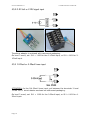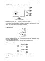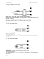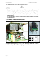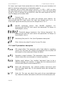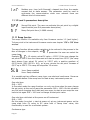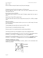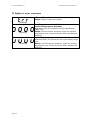
1
USER’S MANUAL
PROCESS CONTROLLER
CH SERIES
ManCH-UK Vers 1.3 May’09
ITALCOPPIE SENSORI s.r.l.
CH SERIES PROCESS CONTROLLER
WARNING
•
If failure or error of this instrument could result in a critical accident of the
system, install an external protection circuit to prevent such an accident
•
Do not turn on the power supply untill all of the wiring is completed.
Otherwise electric shock, fire or malfunction may result.
•
Use this instrument within the scope of specifications. Otherwise fire or
malfunction my result.
•
Do not use this instrument in the place subject to flammable or explosive
gas.
•
Do not touch high-voltage blocks such as power supply terminals, etc.
otherwise electric shock my result.
•
Never disassemble, repair or modify the instrument. This may cause electric
shock, fire or malfunction.
•
Over-temperature protection: Any control system design should take into
account that any part of the system has the potential to fail. For
temperature control systems, continued heating should be considered the
most dangerous condition, and the machine should be designed to
automatically stop heating if unregulated due to the failure of the control
unit or for any other reason. The following are the most likely causes of
unwanted continued heating:
o Controller failure with heating output coinstantly on
o Disengagement of the temperature sensor from the system
o A short circuit in the thermocouple wiring
o A valve or switch contact point outside the system is locked to keep
the heat switched on.
In any application where physical injury or destruction of equipment might
occur, we recommend the installation of independent safety equipment, with
a separate temperature sensor, to disable the hetaing circuit in case of
overheating.
The control alarm signal is not designed to function as a protective measure
in case of controller failure.
•
This is a Class A instrument. In a domestic environment this instrument may
cause radio interference, in wich case the user is required to take adequate
measures.
•
This instrument is protected from electric shock by reinforced insulation. So
please arrange reinforced insulation to the wire for input signals against the
wire for instrument power supply, source of power and load as far as
possible.
CAUTION
Pag. 2
ITALCOPPIE SENSORI s.r.l.
CH SERIES PROCESS CONTROLLER
•
This instrument is manifacured on the assumption that it is used in the
condition of being mounted on the instrumentation panel. Therefore, take
the necessary measures on the equipement side mounted with this
instrument so that the operator personnel are not accessible to high-voltage
blocks in this instrument such as power supply terminals.
•
Always observe precautions described in this manual. Otherwise serious
injury or accident may result.
•
Conduct all of the wiring in accordance with the local codes and regulations.
•
Install a protection device as fuse, etc. in the power supply, input or output
line if necessary.
•
Do not allow metal fragments or lead wire scraps to fall inside this
instrument. This may cause electric shock, fire or malfunction.
•
Firmly tighten each terminal screw at the specified torque. Otherwise electric
shock or fire my result.
•
Do not place any obstacle around this instrument in order not to impede
radiation of heat. And do not close ventilation holes.
•
Do not connect wires to unused terminals.
•
Please apply appropiate power source to instrument according to rated
power show on label over instrument: a wrong power supply could damage
the instrument and my cause short circuit or burn out.
•
Before cleaning the instrument, always turn off the power supply.
•
Remove stains from this instrument using a soft, dry cloth. Do not use a
volatile solvent such as thinner in order to avoid deformation or
decoloration.
•
Do not rub not strike the display unit of this instrument with a hard object.
This controller has been designed with compliance to ‘Regulations on electrical
apparatus (appliance, systems and installations) according to the European
Community directive 73/23/EEC amended by the European Comunity directive
93/68/EEC and the Regulations on the essential protection requirements in electrical
apparatus EN61010- 1 : 93 + A2:95.
It is important to understand that it’s responsibility of the installer to ensure
the compliance of the regulations on safety requirements and EMC.
The products meet the requirements for the European WEEE.
Note:Information in this user’s manual is subject to change without notice. No part of this pubblication my be
reproduced, transmitted, transcribed or stored in a retrieval system, or translated into any language in any form
by any means without the written permission of the Italcoppie sensori s.r.l.
Pag. 3
ITALCOPPIE SENSORI s.r.l.
CH SERIES PROCESS CONTROLLER
1 Ordering code
Note:
Universal input: Thermocouple / Thermoresistence (Pt100 / Pt1000), Volt
linear input (0-1/5 o 0-2/10 with an external adapter), mA linear input (04/20 with shunt external resistor).
RS485 serial interface: galvanic isolation, with Modbus RTU communication.
Multi-function digital input: galvanic isolation, enabled by an external
contact like relay contact, switch, etc..
Power supply for 2 wires transmitter: 24Vcc max. 25mA, with short circuit
protection.
Pag. 4
ITALCOPPIE SENSORI s.r.l.
CH SERIES PROCESS CONTROLLER
2 Installation
Installation must only be carried out by qualified personnel.
To prevent hands or metal touching parts that may be electrically live, the
controllers must be installed in an enclosure and/or in a cubicle.
2.1 CH102 dimensions (measures on mm)
CH102 panel cut-out (measures on mm)
Note: The front of the instrument waterproof, conforms to IP65 with the
instrument mounted on the control panel. In order to assure the
waterproof, check that there is no dislocation of the packing nor clearance
between the instrument and mounting frame with the instrument mounted.
Pag. 5
ITALCOPPIE SENSORI s.r.l.
CH SERIES PROCESS CONTROLLER
2.2 CH402 dimensions (measures on mm)
CH402 panel cut-out (measures on mm)
Note: The front of the instrument waterproof, conforms to IP65 with the
instrument mounted on the control panel. In order to assure the
waterproof, check that there is no dislocation of the packing nor clearance
between the instrument and mounting frame with the instrument mounted.
Pag. 6
ITALCOPPIE SENSORI s.r.l.
CH SERIES PROCESS CONTROLLER
2.3 Mounting procedures
1) Make a rectangular/square holes corresponding to the number of
instruments to be mounted through the panel by reffering to panel
cutout dimensiions.
2) Insert the instrument into the panel from the panel cutout
3) Insert the mounting bracket into the mounting groove of the instrument
(Fig.1)
4) Push the mounting bracket into the instrument until the instrument is
firmly fixed to the panel (Fig. 2)
2.3 Instrument unplugging
-To prevent electric shock or instrument failure, only qualified personnel
should be allowed to pull the internal assembly.
Pag. 7
ITALCOPPIE SENSORI s.r.l.
CH SERIES PROCESS CONTROLLER
-To prevent electrical shock or instrument failure, always turn off the power
before pulling out the internal assembly.
- Electrostatic discharges can damage the instrument; before removing the
instrument from the shell, the operator must discarge himself to ground.
-To prevent injury or instrument failure, do not touch the insternal printed
circuit board
2.3.1 How to pull out the internal assembly
CAUTION: Don’t force to unlock to protect the frame against possible
damage.
Note: Recommended tool: Minus-headed screwdriver (Recommended head
widht:6mm)
3 Environmental ratings
Operating conditions
Temperature
Relative humidity non-condensing
0…50°C
45%...85%
FORBIDDEN Conditions
Corrosive atmosphere
Explosive atmosphere
3.1 Mounting cautions
This instrument is intended to be used under the following environmental
conditions: Overvoltage category II , Pollution degree 2.
Avoid the following when selecting the mounting location:
•
Pag. 8
Ambient temperature of less than 0°C or more than 50°C
ITALCOPPIE SENSORI s.r.l.
•
•
•
•
•
•
•
•
•
•
CH SERIES PROCESS CONTROLLER
Ambient humidity of less than 45% or more than 85% RH
Rapid change in ambient temperature wich may cause condensation
Corrosive or inflammable gases
Direct vibration or shock to the mainframe
Water, oil, chemicals, vapor or steam splashes
Excessive dust, salt or iron particles
Excessive induction noise, static electricity, magnetic fileds or noise
Direct airflow from an air conditioner
Should be used indoord where the system is not exposed to direct
sunlight
Heat to be accumulated radiation heat.
4 Wiring
Despite the fact that the instrument has been designed to work in an harsh
and noisy environmental, it is strongly recommended to follow the following
suggestions.
All the wiring must comply with the local regulations.
¤ The supply wiring should be routed away from the power cables.
¤ Avoid to use electromagnetic contactors, power relays and high power
motors nearby.
¤ Avoid power units nearby, especially if controlled in phase angle
¤ Keep the low level sensor input wires away from the power lines and the
output cables.
¤ If this is not achievable, use shielded cables on the sensor input, with
the shield connected to earth.
¤ Make sure that the power supply voltage is the same indicated on the
instrument.
¤ Switch on the power supply only after that all the electrical connections have
been completed.
¤ Conduct instrument power wiring so as not to be influenced by noise from
the electric equipment power. If the instrument may be affected by external
noise, a noise filter should be used; install the noise filter on the panel wich is
always grounded and minimize the wiring distance between the noise filter
output side and the instrument power terminals.
¤ In accordance with the safety regulations, the power supply switch shall
bring the identification of the relevant instrument. The power supply switch
shall be easily accessible from the operator. To protect the instrument internal
circuits use a 1 Amper 250V fuse:
Pag. 9
ITALCOPPIE SENSORI s.r.l.
4.1 CH102 terminal configuration (MODEL S):
4.2 CH402 terminal configuration (MODEL S):
Pag. 10
CH SERIES PROCESS CONTROLLER
ITALCOPPIE SENSORI s.r.l.
CH SERIES PROCESS CONTROLLER
4.3 Thermocouple input
-
Connect the wires with the polarity as shown
Use always compensation cable of the correct type for the therocouple
used
The shield, if present, must be connected to a proper earth
See programmation instrument chapter to understand how to set the
right type of thermocouple.
4.4 Resistance termometer input (Pt100 IEC – Pt1000 IEC)
-
If a 3 wire system is used, use always cables of the same size (1mm²
min.). Line 10Ω/lead maximum resistance.
When using a 2 wires system, use always cables of the same size
(1,5mm² min.) and put a jumper between terminals 11 and 12.
Over terminals 10-11-12, can be plugged either PT100 or Pt1000
resistance termometer. The Pt100/Pt1000 selection have to be made
by an internal jumper over instrument board, and by SL1 parameter
setting.
4.4.1 Input probe Setting Pt100 or Pt1000
CAUTION:
1) To prevent electric shock or instrument failure, only qualified personnel
should be allowed to pull the internal assembly;to prevent electrical shock
or instrument failure, always turn off the power before pulling out the
internal assembly. Electrostatic discharges can damage the instrument;
before removing the instrument from the shell, the operator must discarge
himself to ground.
Pull out the internal assembly (please refer to chapter ‘How to pull out the
internal assembly’)
2) Set the jumper for Pt100 or Pt1000 accordling your sensor as following:
Pag. 11
ITALCOPPIE SENSORI s.r.l.
CH SERIES PROCESS CONTROLLER
PT100 (Series CH102)
PT1000 (Series CH102)
PT100 (Series CH402)
Pag. 12
ITALCOPPIE SENSORI s.r.l.
CH SERIES PROCESS CONTROLLER
PT1000 (Series CH402)
ATTENTION: The jumper factory default setting is Pt100
3) Pull in the insternal assembly and power on the instrument.
4) On menù level 3 set the parameter SL1 = 1000 (Pt100/Pt1000). (Please
see instrument programmation chapter for more infromations).
4.4.2 Wiring RTD accordling IEC751
4.5 Linear input signals
4.5.1 0-5 Volt or 1-5V signal input
On level 3 menù, set SL1 = 1100 for the 0-5Volt input, or SL1 =1101 for 15Volt input.
Pag. 13
ITALCOPPIE SENSORI s.r.l.
CH SERIES PROCESS CONTROLLER
4.5.2 0-10 Volt or 2-10V signal input
The above adaptor is enclosed with instrument packaging.
On level 3 menù, set SL1 = 1100 for the 0-10Volt input, or SL1 =1101 for 210Volt input.
4.5.3 0-20mA or 4-20mA linear input
ATTENTION: for the 0/4-20mA linear input, put between the terminals 11 and
12 the 250 Ω shunt resistor enclosed on instrument packaging.
On level 3 menù, set SL1 = 1100 for the 0-20mA input, or SL1 =1101 for 420mA input.
Pag. 14
ITALCOPPIE SENSORI s.r.l.
CH SERIES PROCESS CONTROLLER
4.6 4-20mA linear input for 2 wires transmitters
On level 3 menù, set SL1 = 1101 for 4-20mA input sensor.
ATTENTION: The power supply for 2-wires transmitter is 24Vcc±15% max.
25mA. This power supply is short circuit protected.
4.7 Relay output
Note: to increase the relay life, it’s well advised to set the parameter ‘Cycle
time’ higher than 10 seconds.
If you use a load higher than 5°, you must use an external relay.
4.8 Servovalve output
The 2 SPST relay are inter-blocked: only one relay a time will be active.
Maximum load for any relay: 3A @250Vac.
Note: The valve control will be available from next firmware version
Pag. 15
ITALCOPPIE SENSORI s.r.l.
CH SERIES PROCESS CONTROLLER
4.9 Logic output for static relay
Output 15Vcc ±20% max. 35mA* for static relay command.
Note: to have a best regulation, it’s well advised to set the parameter ‘Cycle
time’ like 1 second.
The Logic output (terminals 5 and 6) is shor circuit protected.
*Note: for the hardware version 1_0 the maximum supply current is 12mA
4.10 mA continuous output
Maximum load: 500 Ω
Short circuit protected
The offset selection (0 or 4 / 20mA) have to be made by SL6 parameter on
menù level 3.
4.11 Volt continuous output
ATTENTION: Minimum load: 1KΩ (Max. current 10mA).
Short circuit protection
The offset selection (0 or 2 / 10V) have to be made by SL6 parameter on
menù level 3.
Pag. 16
ITALCOPPIE SENSORI s.r.l.
CH SERIES PROCESS CONTROLLER
4.12 Selection from Volt or mA continuous output
CAUTION:
To prevent electric shock or instrument failure, only qualified personnel
should be allowed to pull the internal assembly;to prevent electrical shock
or instrument failure, always turn off the power before pulling out the
internal assembly. Electrostatic discharges can damage the instrument;
before removing the instrument from the shell, the operator must discarge
himself to ground.
Pull out the internal assembly (please refer to chapter ‘How to pull out the
internal assembly’)
4.12.1 Jumper for Volt continuous output
VOLT CONTINUOUS OUTPUT
For output offset selection (0-10V or 2-10V) set the SL6 parameter on menù
Level 3 (see chapter ’Level 3 description parameters’)
Pag. 17
ITALCOPPIE SENSORI s.r.l.
CH SERIES PROCESS CONTROLLER
4.12.2 Jumper for mA continuous output
CONTINUOUS mA OUTPUT
For output offset selection (0-20mA or 4-20mA) set the SL6 parameter on
menù Level 3 (see chapter ’Level 3 description parameters’)
ATTENTION: The default factory setting is 4-20 mA ouput (only for
instrument with continuous output)
Pag. 18
ITALCOPPIE SENSORI s.r.l.
CH SERIES PROCESS CONTROLLER
5 RS485 serial interface (accordly to EIA RS485 standard)
Use only twisted shield cable.
On last instrument network put a 120Ω resistor between the RS485 lines A and
B (terminal 14 and 15)
To test the serial interface it’s available the CH-SET kit (code SOFT002): the
kint include a RS232/RS485 serial converter, and the Windows® software
Conf-CH to see and set all instrument parameters (it is possible a free
download of Conf-CH software from web site www.italcoppie.it)
The serial interface is galvanic isolated (2,5Kvolt).
Pag. 19
ITALCOPPIE SENSORI s.r.l.
CH SERIES PROCESS CONTROLLER
6 Digital input
ATTENTION: The digital input is galvanic isolated. DON’T wire any supply at
the terminal 16 and 17: this operation may broke the digital input. At the
terminal 16 and 17, wire a free power contact like mechanical switch and relay
contact. For all the digital input functions, see SLA parameter on menù Level 3.
Pag. 20
ITALCOPPIE SENSORI s.r.l.
CH SERIES PROCESS CONTROLLER
8 Front panel description
PV
Green display: Process Value
SV
Orange display: Setting value or Main regulation Output %
OUT1
Green Led: Main regulation Output status
AL1
Red Led: Alarm 1 status
AL2
Red Led: Alarm 2 status
AT
SER
RP
Orange Led: autotuning status (blinking when active)
Green led: serial communicatzion (blinking when active)
Decimal point: Set point ramp (blinking when active)
Key: Store parameter or change mode
Key: switch Auto/Man or shift digit on setting parameter
Keys: changing parameter value
Pag. 21
ITALCOPPIE SENSORI s.r.l.
CH SERIES PROCESS CONTROLLER
9 Operating environment
If any keys are pressed for a time higher 1 minuts, the display automaticly will
show the process value (PV) on upper display, and the Set point (SV) on down
display.
Pag. 22
ITALCOPPIE SENSORI s.r.l.
CH SERIES PROCESS CONTROLLER
9.1 Input type and input range display
At the power the display instrument will show the input type the range and the
measuring unit.
Example: for a controller with the K thermocouple input type and range from 0
to 1372°C:
Table A
* For Pt100/Pt1000 or 0-5V / 0-10V selection see chapter ‘Wiring’.
Pag. 23
ITALCOPPIE SENSORI s.r.l.
CH SERIES PROCESS CONTROLLER
9.2 Parameter setting procedure
Setting Set Value (SV).
Example: following is an example of set value (SV) to 200°C:
Step by step:
1) Press SET key to enter the SV setting mode. The digit wich light brightly
is settable.
2) Press the <A/M key to shift the digit wich light brightly up to the
hundreds digit.
3) Press the UP key to set “2”. Pressing the UP key increase numerals, and
pressing the DOWN key decrease numerals.
4) After finishing the setting, press the SET key. All of the set value digits
light brightly and as a result the instrument returns to the PS/SV display
mode.
Setting parameters other than set value (SV)
L’impostazione dei parametri di programmazione deve essere eseguita nella
stessa modalità sopra riportata, seguendo i passi da 1 a 4.
The setting procedure are the same as those of example (2) to (4) in the
above “Setting set value (SV)”. Pressing the SET key after the setting end
shifts to the next parameter. When no parameter setting is required, return
the instrument to the PV/SV display mode.
Key operational cautions:
• Even if the displayed value is changed, it is not registred. To register it,
press the SET key.
• If the key is not operated for more than 1 minute, the present mode
return to the PV/SV display mode.
Pag. 24
ITALCOPPIE SENSORI s.r.l.
CH SERIES PROCESS CONTROLLER
9.3 AUTO/MAN and MAN/AUTO REGULATION SWITCH
If SL8 parameter (menù level 3) is enabled (xx1x), the instrument can run
either on manual mode (the user make themself a manual regulation setting
the main regulation output) or in automatic mode (the instrument calculate
automaticly the right regulation output to achieve the Setting value )
The switch form Auto. to Man. or Man. to Auto. have to be made as following:
For safety, any time the user switch from Automatic to Manual
regulation, automaticly the regulation output will be set to 0% (OFF).
Next, by UP / DOWN keys will be possible set the desired vaule: the output
actuation will be immediate, without the SET key confirmation.
Note: It’s not possible the AUTO/MAN switch by ‘<M/A’ key if the same
function is enabled on digital input function (Parameter SLA = 0010 on menù
level 3).
Pag. 25
ITALCOPPIE SENSORI s.r.l.
10 Setting parameter Menù
Pag. 26
CH SERIES PROCESS CONTROLLER
ITALCOPPIE SENSORI s.r.l.
Pag. 27
CH SERIES PROCESS CONTROLLER
ITALCOPPIE SENSORI s.r.l.
CH SERIES PROCESS CONTROLLER
11 Programmation parameters table
LEVEL 2 MENU’
Access: Push the SET key for 3 seconds
Display
Description
Setting range
Default value
AL1 Threshold SPH-SPL
10°C
AL2 Threshold SPH-SPL
10°C
Add:5
Add:6
Auto Tuning
0:Disabled
1:Enabled
Proportional
Band
0: ON-OFF Regulation
SPH-SPL
30°C
Integral Time
0:Integral time exclusion
1-3600 seconds
240 seconds
Derivative
time
0:Derivative time exclusion
1-3600 seconds
60 seconds
Add:7
Add:8
Add:9
Add:10
Add:11
0
Disabled
Integral time 100%: No limitation
limitation
1-99%
100%
Cycle time
1-100 seconds
1 sec. (Logic Out.)
20 sec. (Relay Out.)
Offset PV
-1999/+1999
0°
Lock Function
See Table B
-
Lock code
See Setting parameter menù
-
Add:12
Add:16
Add:17
Add:18
LIVEL 3 MENU’
Access:from Livel 2, set Lock =
=
Display
then push SET + <A/M keys togheter
Description
Input sensor
selection
Pag. 28
and
Setting Range
0000
0001
0010
K
J
E
0011
0100
0101
N
R
S
0110
0111
B
T
1000
Pt100/Pt1000
Default value
0001
Thermocouple j
See Note 1
Note:
*The 0-10V or 2-10V input,
need the enclosed adaptor.
(see chapter ‘wiring’).
**For current input signal,
ITALCOPPIE SENSORI s.r.l.
CH SERIES PROCESS CONTROLLER
1001
Cu50
1010
1011
1100
0-5V*
1-5V*
0-20mA**
1101
4-20mA**
connect the enclosed 500Ω
shunt resistor (see chapter
‘wirement’)
Add:19
Add:20
Unit of
Temperature
xxx0
xxx1
Reserved
Alarm 1
setting
Add:22
Alarm 2
setting
Add:23
Action and
offset
selection (the
Add:24
last one only for
continuous output)
0000 (°C)
-
-
x000
x001
x010
Disabled
Deviation high
Deviation high/low
x011
x101
Process high
Deviation low
x110
x111
Band
Process low
0xxx
Without suppressing
1xxx
x000
x001
x010
With suppressing
Disabled
Deviation high
Deviation high/low
x011
x101
Process high
Deviation low
x110
x111
Band
Process low
0xxx
Without suppressing
1xxx
xxx0
xxx1
X0xx
x11x
x10x
xxx0
xxx1
With suppressing
Direct action
Reverse action
Relay or Logic output
0-20mA | 0-10V output
4-20mA | 2-10V output
xx0x
xx1x
Power on
manual out.
0xxx
1xxx
Man. out = 0%
Last man. out set
Regulation
Selection
xx0x
xx1x
Automatic Reg.
Selection Auto/Man
Add:25
NOàNC
NCàNO
NOàNC
NCàNO
0001
Deviation high
Without suppressing alarm
at the power on
0101
Deviation low
Without suppressing alarm
at the power on
0101:for instruments
with continuous output
Trigger
Trigger
Trigger
Trigger
Alarm relay
trigger type
Pag. 29
°C
°F
AL1
AL2
0001:For instruments
with Relay or logic output
0000
AL1:Trigger NoàNc
AL2:Trigger NoàNc
0110
Man. Power on = 0%
Regulation Auto/Man
Serial interface enabled
ITALCOPPIE SENSORI s.r.l.
CH SERIES PROCESS CONTROLLER
Serial
interface
Add:26
x0xx
x1xx
Reserved
Disabled
Enabled
Don’t change the default value
Digital input
0000
0001
0000
No function
0011
No function
Switch from
SP<->SP2
Swithc from
AUTO<->MAN
Keyboard lock
1xxx
0xxx
Ramp enabled
Ramp disabled
0000
Disabled
0010
Add:28
Add:29
Set point
ramp
1111
LEVEL 4 MENU’
Access:from Level 2, set Lock =
=
Display
and
then push the SET key
Description
Setting Range
Set Point High See Table C
limit setting* *High linearization value for
linear input Volt/mA
Default value
1200°C
See Note 1
Add:30
Set Point Low
limit setting*
See Table C
* Low linearization value for
linear input Volt/mA
Decimal point
0-3
0
Add:31
0
No decimal point
Add:32
On-OFF control 0-100.0
Hysteresis
1.0°C
Add:33
Add:34
Add:35
Add:36
Alarm 1
Hystersis
0-100.0
1.0°C
Alarm 2
Hystersis
0-100.0
1.0°C
% Autotuning
Set point
0-100%
80%
Filter
Add:37
0:Disabled
1:Enabled
1
Filter enabled
MENU’ LEVEL 5
Access:from Level 2, set Lock =
=
Pag. 30
and
then push the SET key
ITALCOPPIE SENSORI s.r.l.
Display
CH SERIES PROCESS CONTROLLER
Description
Setting range
Output Offset
0.0-100.0%
Regulation
output power
limit
Serial address
0.0 – 100.0%
Default value
0.0%
Add:38
Add:39
100.0%
0: Disabled
1-255
Baud rate
0:
2400bps
1:
4800bps
2:
9600bps
3:
19200bps
Code Bit
Parity
Communication
0
8
None
parameters
1
8
odd
2
8
Even
Modbus delay 0-2000mS
LEVEL 6 MENU’
Access:from Level 2, set Lock =
=
Display
Add:2
Add:40
1
2
9600bps
Stop bit
1
1
1
0000
No parity:N-8-1
0mS
and
then push the SET key
Description
Second Set
Point
Setting range
Default value
SPH-SPL
20°C
Set point ramp 1-900 minutes
time
1 minute
Note 1: for the software version 1_1 the default sensor is thermocouple K and the set point
limit is 1372°C.
Input probes range
Input probe
Range
Range SPL Range SPH
K
0÷1372°C
0°C
1372°C
J
0÷1200°C
0°C
1200°C
R*
0÷1769°C
0°C
1769°C
S*
0÷1769°C
0°C
1769°C
B*
0÷1820°C
400°C
1820°C
E
0÷1000°C
0°C
1000°C
N
0÷1300°C
0°C
1300°C
T
0.0÷400.0°C
0.0°C
400.0°C
Pt100/Pt1000
-199.9÷649.0°C
-199.9°C
649.0°C
0/4-20mA
-1999÷+1999
-1999 u.i.
+1999 u.i.
0/1-5V 0/2-10V
-1999÷+1999
-1999 u.i.
+1999 u.i.
Table C
*Input accuracy is not guarantee from 0 to 399°C.
Pag. 31
ITALCOPPIE SENSORI s.r.l.
CH SERIES PROCESS CONTROLLER
11.1 Alarms description
The following graphical representations are referred to SL7 parameter = xx00
NOàNC. For more information over SL7 parameter, see next chapter.
SV:Set Point value
AL: Threshold Alarm (AL1 / AL2)
PV: Process value
DEVIATION HIGH (code x001):
HYS
SV
ON
SV+AL
PV
SV
PV
DEVIATION LOW (code x101):
HYS
ON
SV-AL
DEVIATION HIGH/LOW (code x010):
HYS
ON
SV-AL
HYS
ON
SV
SV+AL
ON
HYS
PV
BAND (code x110):
HYS
SV-AL
SV
SV+AL
PV
PROCESS HIGH (code x011):
HYS
SV
ON
AL
PV
PROCESS LOW (code x111):
HYS
ON
AL
Pag. 32
SV
PV
ITALCOPPIE SENSORI s.r.l.
CH SERIES PROCESS CONTROLLER
The black ‘ON’ area indicate the relay status alarm: ON = Relay contact closed.
11.2 Alarm trigger
:
Alarm relay trigger type
Example with Alarm 1 as deviation high:
If SL7 = xxx0 so the trigger is NOàNC (black area ON: realy closed contact):
If SL7 = xxx1 so the trigger is NCàNO (black area ON: realy closed contact):
11.3 Alarm Hysteresis
On menù Level 4, it is possible set the alarms Hysteresis by AH1 and AH2
parameters.
:
:
Alarm 1 hysteresis (for thermocouple and RTD sensor this value
it’s always on tenth of degree)
Alarm 2 hysteresis (for thermocouple and RTD sensor this value it’s
always on tenth of degree)
Hysteresis example over Alarm 1:
= 50°C
= 5.0°C
= 001 (deviation high)
SV = 100°C
Pag. 33
ITALCOPPIE SENSORI s.r.l.
CH SERIES PROCESS CONTROLLER
11.4 Alarm suppressing at power on
The ‘alarm suppressing at power on’ function can be enabled by setting the
most significant bit of SL4 parameter for Alarm 1 (SL4 = 1xxx) and SL5
parameter for alarm 2 (SL5 = 1xxx).
This function suppress the alarm at the power on ; instrument alarm often
occurs immediatly after power on or set point change. Take electrical furnace
temperature control (heating control) as an example;the actual temperature is
far below target set point at power on. If lower alarm is configured, then the
alarm condition may satisfied at power on; but in fact the control system my
not have problem. If an alarm condition is satisfied again after it is cleared,
then the alarm function is started up.
The alarm suppressing will start at the instrument power on and also at any
Set point (SV) changing.
11.5 Level 2 parameters description
:
Alarm 1 threshold
:
Alarm 2 threshold
For alarms functionality see chapter ‘Alarms description’
:
Auto-tuning
1: Auto-tuning enabled (orange AT led blinking)
0: Auto-tuning disabled (orange AT led off)
The autotuning functionality check the process and automaicly calculate the
main P.I.D. paramaters (proportional band, integral time, derivative time) to
achieve the best regulation without over or undershoot.
The autotuning can NOT be activated on the following situations:
- The input sensor is under or over range;
- The input sensor is broke
- The instrument is on Manual regulation
The autotuning STOP at the following situations:
- If input sensor broke or go under or over-range
- The user change the regulation from automatic to manual
- The user change Set point (including the situation ‘switch Set Point’
from digital input)
- The user set the proportional band = = 0 (ON-OFF control).
The autotuning is made by an ON-OFF control over a % set point defined on a
parameter (menù Level 4).
Pag. 34
ITALCOPPIE SENSORI s.r.l.
CH SERIES PROCESS CONTROLLER
= 100% then the tuning will be made over the same Set point
If
showed on instrument orange display: on the other case, (when Atp < 100%)
the tuning Set point will be automaticly calculated with % of Atp parameter.
Example: If Set point = 150°C and the
= 80%, then the tuning will be
made over Set Point = 120°C.
The tuning will check the process by an ON-OFF regulation: over this step,a big
dangerous overshoot should be reach: so, before start the autotuning
procedure, set the
parameter accordly to your system requred. At the
end of autotuning process, the instrument will calculate the main PID
parameters and il will start to regulate with right Set Point (with reference to
above example, the autotuning will be made over SP=120°C, but at the end of
autotuning procedure the regulation will be made automaticly to SP = 150°C
with new PID calculated parameters).
:
Proportional band (on°C or °F or engineering units).
Is the action wich the control output varies in proportion to the deviation
between the setting vale (SV) and the processing temperature (PV).
Example:
following:
= 50°C, SV = 250°C. The proportional band could be draw as
I the proportional band is narrowed, even if the output changes by a slight
variation of the processing temperature, better control results can be obtained
as the offset decreases.
However, if the proportional band is narrowed too much, even slight
disturbances my cause variation in the processing temperature, control action
changes to ON/OFF action and so hunting phenomenon occurs.
11.6 ON-OFF regulation
If the proportional band = 0, then the kind of control is ON-OFF.
When the controller is configured to work in ON / OFF mode, the output of the
controller only takes two values, 0% or 100%. For example, in a temperature
control process, the output takes the value of 100% when the process is under
the setpoint and 0% when the process is above the consignment. The following
graph shows the “saw tooth” shape with which the process reacts under this
kind of control.
Pag. 35
ITALCOPPIE SENSORI s.r.l.
CH SERIES PROCESS CONTROLLER
In this control mode, the user may programme a hysteresis between the
connections and the disconnections
:
ON-OFF Hysteresis (menù level 4) (for thermocouple and RTD
sensors this value is on tenth/degree)
If the instrument work on manual mode, the user can set only 2 values ON
(permanent output) and OFF (no output). The lower display will show:
Output ON
Output OFF
:
Integral time (0-3600 seconds)
Integral action is used to eliminate offset. When the integral time is short, the
returning speed to the setting point is accelerated; however, the cycle of
oscillation is also accelerated and the control becomes unstable.
It is possible exclude the integral time by setting the value = 0.
:
Derivative time (0-3600 seconds)
Derivative action is used to restore the change in the processing temperature
according to the rate of change. It reduces the amplitude of overshoot and
undershoot widht.
If the derivative time is shortened, restoring value becomes small, and if the
derivative time is made longer, an excessive returning phenomenon my occur
and the control system my be oscilleted.
Pag. 36
ITALCOPPIE SENSORI s.r.l.
CH SERIES PROCESS CONTROLLER
: Integral time limitation
This parameter can limitate the integral action. If = 100% NO integral time
limitation occour.
IMPORTANT: Generally, a proportion must be maintained between integral
time(Ti) and derivative time (Td) so that Td takes the value of a quarter of the
value of Ti. In other words. Td = Ti / 4 (example: Ti=240, Td=60).
Therefore, the controller output will vary between 0% and 100% as a result of
the sum of the Proportional, Integral and Derivative actions.
:
Cycle time (1-100 seconds)
A controller with a modulated output doses the amount of power supplied to
the process between 0% and 100%. As a modulated output there might be:
Output modulated by pulses: When it is a question of dosing the power
supplied to the process with a device such as a relay or a solid status relay, it
is achieved by varying a connection time on a fixed cycle which in the
controller is configured by this parameter
.
For example, with a 30-second output cycle, the power delivered to the
process can be dosed between 0% and 100% in fractions of 0.3 seconds (30
sec. / 100). See the following table supposing a cycle of 30 seconds:
To give the
process…
the output must
be active for …
...10% power
... 25% power
... 50% power
... 80% power
3 seconds
7.5 seconds
15 seconds
24 seconds
… and
deactivated
for …
27 seconds
22.5 seconds
15 seconds
6 seconds
Total cycle
(seconds)
3+27=30”
7,5+22,5=30”
15+15=30”
24+6=30”
... 100% power
30 seconds
0 seconds
30+0=30”
(there is no
disconnection of
the output)
This means that every 30 seconds the controller activates the output, but
depending on the percentage that it should deliver to the process, it will take
more or less time to carry out the disconnection.
The cycle time it’s a valid parameter only for the relay or logic output; for relay
output we suggest to set values high than 20 seconds (to increase the contact
relay life); for logic output, we suggest to set this parameter = 1 seconds to
achieve best regulation.
:
Deviation of the indication with respect to the read value of the
variable. For instance, if the instrument takes a reading of 200 and
20, the value of the measurement will be 220 (200 + 20).
Pag. 37
=
ITALCOPPIE SENSORI s.r.l.
CH SERIES PROCESS CONTROLLER
Details of lock levels
0000
0001
0010
0011
0100
0101
0110
0111
1000
No lock
Only SV and alarms can be set
Only setting parameters other than alarms can be set
Only SV can be set
Only setting parameters other than SV can be set
Only alarms can be set
Only setting parameters other than SV ans alarms ca be set
Lock of all parameters
With
parameter can
programmation
parameter
parameters table’)
enable the access to any
level
(see
‘Programmation
Table B
Note:also when Lock is > 0 all parameters can be showed: the lock it’s relative
only to setting values.
11.7 Level 3 parameters description
Input sensor selection (see ‘Programmation parameters table)
:
:
Unit
of
temperature
parameters table’)
:
,
:
measurement
(see
‘Programmation
Reserved parameter
,
: Alarms parameters (see ‘Alarm description’)
Direct/reverse action selection; analog output offset selection (see
‘Programmation parameters table’).
SL6 = xxx0 à Direct action
SL6 = xxx1 à Reverse action
Pag. 38
ITALCOPPIE SENSORI s.r.l.
CH SERIES PROCESS CONTROLLER
Ofsset output selection:
SL6 = 011x à Regulation output 0-20mA | 0-10Volt
SL6 = 010x à Regulation output 4-20mA | 2-10Volt
Type of output (read only):
SL6 = x0xx à Regulation output: relay or logic 0-15Vcc
SL6 = x1xx à Regulation output: continuous Volt o mA
:
Manual regulation selection / Enable serial interface
SL8 = 0xxx :When
output
SL8 = 1xxx :When
output
off.
the instrument
at the power-on
the instrument
at the power on
can switch on manual mode, the manual
is always 0%.
can switch on manual mode, the manual
is the last manual output set before power-
SL8 = xx0x : The instrument regulation it’s only automatic
SL8 = xx1x : The user can select by <M/A key either regulation: manual or
automatic. On manual mode will be the user to set the right output
to achieve the set point. For more infromation see ‘Auto/Man and
Man/Auto regulation swicth’.
SL8 = x0xx : Serial communication disabled
SL8 = x1xx : Serial communication enabled: the instrument can be integrate in
a modbus network
:
Digital input functions selection
SLA = 0000: No function liked to digital input
SLA = 0001: Swich from SV and SP2. Contact close: the second set point
(SP2) is active. Contact open: the main SV is active.
SLA = 0010: Automatic / manual regulation switch. Contact closed: manual
regulation with start output = 0%. Contact open: automatic
regulation. This functionality it’s valid only when the parameter SL8
= xx1x.
SLA = 0011: Keyboard lock. Contact close: keyboard lock. Contact open: the
user can change the parameters by keyboard
:
Enable Ramp set point
SLB = 1xxx
Set point ramp enabled
SLB = 0xxx
Set point ramp disabled
See also Chapter 11.11
11.8 Level 4 parameters description
,
: For thermocouple and RTD input sensor, these parameters
are the higher (SPH) and lower (SPL) set point limitation.
Pag. 39
ITALCOPPIE SENSORI s.r.l.
CH SERIES PROCESS CONTROLLER
For linear input signal these parameters are either the set point limitation but
also the maximum and minimum linearization values.
For example: with 0-10Volt input sensor and SPL = 0, SPH = 1000, so when
the input signal will be 0 over PV display will be show 0; when the input signal
will be 5V, over PV display will be show 500; when the input signal will be 10V,
over PV display will be show 1000.
:
Decimal point
With this parameter the user can select the decimal point position. For
thermocouple and RTD input sensor the value can change from 0 to 1; fro
linear input signal the decimal point can be changed from 0 to 3.
ON-OFF Hysteresis control. See ‘ON-OFF regulation’. For
thermocouple and RTD input sensor this parameter it’s always on
tenth/degree (xxx.x).
:
: Threshold alarms hysteresis. See ‘Alarms description’. For
thermocouple and RTD input sensor this parameter it’s always on
tenth/degree (xxx.x).
,
:
:
Autotuning Set point %. See ‘Level 2 parameter description’
Filter. Active only when PV value it’s near SV value.
11.9 Level 5 parameters description
Pag. 40
:
PID output offset. This parameter add a fixed offset to regulation
output. Any time the user change this parameter have to power off
then power on the instrument to see the effect.
:
Regulation output limitation. This parameter clamp the maximum
output value either on automatic or manual regulation.
:
Modbus serial address. Any modbus instrument have to be a
different address over network; 0 means that the instrument don’t
communicate (Serial communication OFF).
:
Baud rate (bit/seconds). Any network modbus instrument could
have the same baud rate. For the possible baud rate see table on
‘Menu level 5’
:
Parity bit. The user can select from parity bit as none/odd/even.
Any network modbus instrument could have to the same parity bit.
ITALCOPPIE SENSORI s.r.l.
:
CH SERIES PROCESS CONTROLLER
Modbus sync. time (milli-Seconds): elapsed time from the master
request end to slave answer. This parameter could be used to
syncronize the communication when over network there are
different kind of instruments.
11.10 Level 6 parameters description
:
:
Second Set point. The user can activate this set point by a digital
input function (see SLA parameter description).
Ramp Set point time (1-9999 minuts)
11.11 Ramp function
The ramp function it’s available only from firmware version 1.2 (and higher).
To know wich is the instrument firmware version see chapter ‘HW e SW show
version’.
The ramp function allows sudden variations to be reduced in the process in the
face of changes in the setpoint; with
ramp slope.
parameter the user can select the
= 15 minuts, actual PV value = 150°C. If the user change the
Example:
set point to 250°C then the instrument will start a ramp from 150°C (the ramp
start always from actual PV value) to 250°C with a positive gradient of
6,6°C/minut (250-150/15= 6,6); so at any minuts the set point increase of
6,6°C up to 250°C. The ramp will stop after 15 minuts.
:
1xxx: Ramp enabled
0xxx: Ramp disabled
It is possible set two different ramp type: one-shot and continuous. Moreover
it’s possible define if the ramp have to start at any instrument power on.
One-shot type
SLB = 1001
In One-shot mode the ramp function run only one time when the user change
the set point; at the end of ramp the parameter SLB = 1000. On this situation
any Set point changing don’t start any new ramp; to start a new ramp the user
have to set again SLB = 1001 and re-change the set point value.
One-shot type with start at the power on off instrument
SLB = 1100
On this mode (one-shot + start at power on) at any instrument power on the
ramp start from PV value to SV value with a ‘Ramp time’ value; this
functionality is used for a soft-start system.
Continuous type
Pag. 41
ITALCOPPIE SENSORI s.r.l.
CH SERIES PROCESS CONTROLLER
SLB = 1010
On this mode the ramp will start at any Set point changing.
Continuous type with start at the power on off instrument
On this mode the ramp will start at any Set point changing and at any
instrument power on.
Active Ramp function indication
The decimal point blinking on first right SV display means that the ramp is
active.
Switch from SP and SP2 by digital input
The ramp start also when the user change the set point (SV<->SP2) by digital
input.
Ramp & exceptions
If during ramp mode the sensor broke or go on over or under range, the ramp
stop immmediatly.
To stop/disable the ramp the user have to set SLB = 0000.
During tuning it’s not possible activate a ramp.
During a ramp it’s not possible start the autotuning procedure.
The ramp can start only if the gradient is lower than 10digits/seconds.
Example:ST=1minut(60seconds), PV=12.0°C, SV=50.0°C. The gradient will be
SV-PV/ST = 500-120/60 = 6,3digits/second, so the ramp CAN start.
Example:ST=1minut(60seconds), PV=12.0°C, SV=74.0°C. The gradient will be
SV-PV/ST = 740-120/60 = 10,3digits/second, so the ramp CAN NOT start.
12 HW and SW show version
To see the Hardware and software version, power on the instrument with
DOWN key pressed.
Pag. 42
ITALCOPPIE SENSORI s.r.l.
CH SERIES PROCESS CONTROLLER
13 Display at error occurrence
EEprom failure (incorrect set data write, ecc..)
Action: Please contac your reseller
(blinking)
(blinking)
(blinking)
Pag. 43
OverRange/sensor broke/Not wired
sensor/wrong sensor wirement
Measured value (PV) exceeds the high input display
range limit.
Action:Chek the sensor wirement, check the process
temperature, and check the sensor with a professional
calibrator.
UnderRange/ wrong sensor wirement
Measured value (PV) exceed the low input display range
limit.
Azione: Chek the sensor wirement, check the process
temperature, and check the sensor with a professional
calibrator
ITALCOPPIE SENSORI s.r.l.
CH SERIES PROCESS CONTROLLER
14 RS485 serial interface with MODBUS-RTU protocol communication
The MODBUS (RTU or ASCII) protocol is a very popular standard for field bus
applications: it is ideal for reliably and efficiently handling large data flows with
numerous variables. Thanks to this standard, the Evo Ser series can be hooked
up directly to the majority of commercially available PLC’s and SCADA
packages, with the option to connect these modules together with other
devices (PLC’s, operator panels, CNC equipment, etc...) over a single network.
CH series devices are equipped with an RS-485 serial port with 2 wire
connection; please see relative chapter for wirement.
The RS485 serial interface is galvanically isolated (2,5KVolt): if the master unit
is equipped with an RS232 serial interface, we recommend using an isolated
converter. If the master unit is equipped with an RS485 port, we recommend
using an RS485 galvanic separator.
14.1 Communication cable layout
To prevent external interference with the serial signal and obtain the highest
efficiency between the master and the CH series devices, a number of small
precautions must be observed.
The most important (and simplest) is to physically separate the power and
communications cables and route them as far as possible from contactors,
electromagnets, powerful motors, etc.
The type of cable used is essential to the operation of the system as a whole.
The most important specification is capacitance per metre (pF/m); the lower
the capacitance of the cable the longer the line may be. In this regard, the
power cable and generic ducting cables are absolutely to be avoided inasmuch
as they have a very high capacitance per metre. Furthermore, to obtain high
resistance to disturbances, the cables must be twisted together and equipped
with a metal shield connected to a good ground plant (at one end only), with
a characteristic impedance of around 120 ohm.
If these simple precautions are observed, the line will operate at its highest
possible speed over a distance of up to 1,200 metres.
The two devices (master and last slave) at each end of the line must be
terminated; star type connections are not allowed, since each wire would be
terminated, thus significantly lowering the impedance of the line and blocking
communications completely.
14.2 Guide to RS-485 network
The RS485 serial interface is based on a balanced differential communications
line with typical impedance of 120 ohm. The maximum cable run is not
defined, but depends on the speed of communications, the signal noise ratio
and the quality of the cable used. The line is generally guaranteed to operate
up to 1,200 m.
The cable can be unshielded if the run is of a few metres in an electrically only
slightly noisy area. For distances from 15 to 100 m, you can use a shielded
Pag. 44
ITALCOPPIE SENSORI s.r.l.
CH SERIES PROCESS CONTROLLER
and twisted cable without special characteristics, while for connections over
100 metres, we recommend using a category 5 cable.
The ends of the line must be terminated in parallel with a 120 ohm resistance.
The shield of the cable must be connected to pin Nr.13 (SG) on the CH
connector, and grounded at one end only; if the other end must be grounded
to reduce disturbance, fit a 10nF capacitor.
14.3 Capacitive load of the line
With very long cables, the capacitance of the cable starts to be the dominant
factor in power consumption. For this reason, it is not usually possible to
achieve maximum cable run and highest transmission speed in a single
installation.
The following table is a rough guide to the compromise between distance and
speed
Baud Rate
2.400
4.800
9.600
19.200
Total max.
capacitance of cable
(pF)
200.000
100.000
50.000
25.000
The capacitance of the cable (in pF/m) can be obtained from the manufacturer,
and is typically between 50pF/m (for high quality cables, e.g. category 5) and
100pF/m.
Naturally, the resistance and inductance of the cable, which may be neglected
for short cable runs, influence the signal level if the cable run is very long. It is
hard to give general rules, since he minimum section depends on the line
termination, number of connected devices and spacing between them. In case
of doubt, always choose the larger section cable.
14.4 Line polarity
As per the RS485/422 standard, the line connections are indicated as A and B:
the line may however be marked differently, for example HI/LO or +/-. It is
usually assumed that A/B correspond respectively to HI/LO, or +/-, but this is
not always the case. In case of malfunction, try swapping the connections even
if everything seems to be OK.
Pag. 45
ITALCOPPIE SENSORI s.r.l.
CH SERIES PROCESS CONTROLLER
15 Modbus RTU
15.1 Preliminary notes
MODBUS was used primarily in industrial applications, thanks to the
dominating presence of Modicon in the PLC market, which developed the
standard for its own equipment.
When the specifications became public and open, the Modbus protocol was
adopted in numerous automation applications and subsequently in all sectors.
For many years it has been a de facto standard, and the Modbus protocol can
be found on any “intelligent” equipment (IFD - Intelligent Field Device):
programmable controllers, NC, drivers, man/machine terminals, measurement
equipment, etc.
15.2 Communication model
The connection is made over an RS-485 multipoint network, typically by means
of a twisted two-wire cable with shielding.
The communications technique is of the Master-Slave type, multipoint halfduplex, in which only the Master (typically a Host PC) can initiate
communications with a request (“Query”), while the Slaves respond with a
message (“Response”) only to the queries addressed directly to themselves.
One master can control up to 247 slaves on a single line; note that this is a
logical limit of the protocol, however the physical interface may further limit
the number of devices, for example, the standard RS-485 interface supports a
maximum of 31 slaves on a single line. If we replace the last device on the line
with a bridge or repeater, a further 31 slaves can be installed, an so on up to
the logical limit.
The Modbus protocol establishes the format of the query, which contains the
address of the slave being queried, a function code for the requested action,
various fields for exchanging data (registries, coils, etc...), and a field to check
for communications errors (CRC).
The slaves respond with messages which are structured in the same way; if a
slave is unable to complete the requested action, it sends an error code in the
response.
15.3 Transmission
The CH series devices employ the RTU Modbus protocol; the serial mode and
setup must be the same for all devices on the Modbus network.
In RTU (Remote Terminal Unit) mode, the messages, which are composed of
single bytes, are sent in the form of two 4 bit hexadecimal characters. The
advantage of this is that the quality of data exchange is better than that
provided by the
ASCII mode for a given transmission speed. Each
communications packet must be transmitted in a continuous cycle.
Pag. 46
ITALCOPPIE SENSORI s.r.l.
CH SERIES PROCESS CONTROLLER
The format for each RTU mode byte is:
Coding system: 8 binary bits, from 00 to FF
Two hexadecimal characters are contained in each 8 bit field of the message.
Each 8 bit character of the message corresponds to one data byte.
Character format:
1 start bit ,
8 data bits,
the 1st bit is the least significant,
no parity bit (None),
1 stop bit.
Address: Modbus transactions always involve the master, which controls the
line, and one slave at a time (except for broadcast messages, but these are
not implemented in the Ch series firmware). To identify the target of the
query, the first byte contains the numerical address of the desired slave. Each
slave has a unique address number which uniquely identifies it. Legal
addresses run from 1 to 247, while 0, which cannot be assigned to a slave, at
the head of a message identifies the message as “broadcast”, directed at all
slaves at the same time. Only messages which do not require a response to
complete may be transmitted as broadcast, in other words, only assignments.
Function code:
The second character of the message identifies the function to be executed, to
which the slave responds with the same code to indicate that the function has
been executed. The Evo Ser system implements a subset of Modbus functions,
including:
Modbus function code
01
02
03
04
05
06
07
Function
Read Coil status
Read Input Status
Read Holding register
Read Input register
Force single Coil
Preset single register
Read Status
In the CH series devices, functions 01 and 02 are operatively identical and
interchangeable, as are functions 03 and 04.
15.4 CRC16
The CRC field is the last in the section and allows the master and the devices
to detect transmission errors. Occasionally, due to electrical noise or
interferences of another kind, some modification may be caused in the
message while it is being transmitted. CRC control of errors ensures that the
receiver devices or the master will not perform incorrect actions due to an
accidental modification of the message.
Pag. 47
ITALCOPPIE SENSORI s.r.l.
CH SERIES PROCESS CONTROLLER
The CH controller does NOT send any reply when it detects a CRC error in the
section received.Stop bits and parity bits are not considered in calculating the
CRC. Only the data bits.
The sequence for the CRC calculation is described in the following:
1. Load a 16 bit register at 1’s.
2. Perform an exclusive OR of the first 8 bits received with the high byte of the
register, saving the result in the register.
3. Move the register one bit to the right.
4. a) If the displaced bit is a 1, carry out an exclusive OR of the value of 1010
0000 0000 0001 with the content of the register and save it in the register.
4. b) If the displaced bit is a 0, return to step 3.
5. Repeat steps 3 and 4 to 8 bit displacements.
6. Carry out an exclusive OR of the following byte of the section with the 16 bit
register.
7. Repeat steps 3 to 6 until all of the bytes of the section have been
processed.
8. The content of the 16 bit register is the CRC, which is added to the message
with the most significant bit first.
15.4.1 CRC16 Visual Basic example
Function CRC16(Stringa As String) As String
Dim N As Integer, I As Integer, NByte As Integer
Dim CRC As Long, a As Byte
Dim Buffer As String
NByte = Len(Stringa)
CRC = 65535
For i = 1 To NByte
a = Asc(Mid$(Stringa, I, 1)) ‘C(I)
CRC = (CRC Xor a) And &HFFFF
For N = 0 To 7
If CRC And 1 Then
CRC = (CRC \ 2)
CRC = (CRC Xor 40961)
Else
CRC = CRC \ 2
End if
Next
Next
Buffer = Right$(“0000” + Hex$(CRC And &HFFFF), 4)
CRC16 = Chr$ (“&H”+ Right$(Buffer, 2)) + Chr$(“&H” + Left$(Buffer,2))
End Function
Pag. 48
ITALCOPPIE SENSORI s.r.l.
15.5 CRC16 calculation flow chart
Pag. 49
CH SERIES PROCESS CONTROLLER
ITALCOPPIE SENSORI s.r.l.
CH SERIES PROCESS CONTROLLER
15.6 Message synchronisation
The message between the transmitter and receiver is synchronised by inserting
a pause between messages of at least 3.5 times the time it takes to transmit a
character; this pause therefore depends on the baud rate.
If the receiver does not receive for a period of 3.5 characters, it assumes the
previous message to be complete and considers the subsequent byte to be the
first of a new message, and thus an address.
The network devices constantly monitor the bus, including the silent pause.
The admissible characters transmitted for all fields are 8 bit numbers, hence in
the range 0 to 255.
The first transmitted field is the address of the device.
When the first field (address) has been received, each device decodes it to
determine whether the message is addressed to itself.
After the last transmitted character, an interval of 3.5 characters follows to
indicate the end of the current message. A new message can start immediately
after expiry of this delay. The entire message frame must be transmitted
continuously.
If a new message starts before the delay of 3.5 characters has expired, the
receiver will consider it to be the continuation of the previous message; this
generates an error, since the value of the last field (CRC) will not be valid for
the combined messages.
START
ADDRESS
FUNCTION
DATA
T1-T2-T3-T4
1 CHAR
(8 bits)
1 CHAR
(8 bits)
N CHARS
(n x 8 bits)
CRC
CHECK
2 CHARS
(16 bits)
END
T1-T2-T3-T4
16 Modbus functions
We describe in detail the modbus functions implemented on CH series devices.
16.1 Read N Bit (function code 01 or 02)
This function allows the user to obtain the logical values (ON / OFF) of the bits
of the addressed device. The reply data are packed in bytes in such a way that
the first bit requested occupies the bit of least weight of the first data byte.
The following carry on so that if they are not a number that is a multiple of 8,
the last byte is completed with zeros.
Master-device section:
Device
address
1 byte
Pag. 50
Function
code
(01 o 02)
1 byte
Address of
the first bit
MSB
LSB
Number of bit to
be read (max 255)
MSB
LSB
CRC
MSB
LSB
ITALCOPPIE SENSORI s.r.l.
CH SERIES PROCESS CONTROLLER
Device-master section:
Device
address
Function
code
1 byte
1 byte
Number
of bytes
read
1 byte
First ...........
data
byte
1 byte ...........
Last
data
byte
1 byte
CRC
MSB
LSB
Example: Read 2 bits from the bit with address 2 (AL1 and AL2 status), of
the controller with the address 2.
Master-device section:
Device
address
02
Function
code
01
Address of
the first bit
00
02
Number of bit to
be read (max 16)
00
02
Number of
bytes read
01
First data byte
CRC
1C
38
Device-master section:
Device
address
02
Function
code
01
11
CRC
91
C0
The reply tell us that the coil with address 2 is active (value = 1) so the AL1
= ON and the coil with address 3 is NOT active (value = 0) so the AL2 = OFF.
Excluding the first 2 bits the others bit are not importants.
It is possible read up to 16 bit togheters.
16.2 Read N registers (function code 03 or 04)
This function enables the user to obtain the vaues of the registers of the
addressed device.
These registers store the numerical values of the
parameters and variables of the controller.
Master–device section:
Device
address
1 byte
Function
code
(03 / 04)
1 byte
Address of
Number of
first register register to be read
( max 16)
MSB
LSB
MSB
LSB
CRC
MSB
LSB
Device–master section:
Device
address
Function
code
1 byte
1 byte
Pag. 51
Number
of byte
read
1 byte
Value of .....
first
register
MSB LSB .....
Value of
CRC
last
register
MSB LSB MSB LSB
ITALCOPPIE SENSORI s.r.l.
CH SERIES PROCESS CONTROLLER
Example: Read 2 register from the register with address 0 (Process value
and Set Value), of the instrument address 1.
Master–device section:
Device
address
Function
code
01
03
Address of first
register
00
Number of
register to
be read
00
02
00
CRC
C4
0B
Device-master section:
Device
address
Function
code
01
03
Number
of bytes
read
04
Value of
first
register
00
61
Value of
last
register
00
50
CRC
AB
D1
The reply tell us that the register 0 and 1 have respectively the hexadecimal
value 0x0061 (PV = 97°C) and 0x0050 (SV = 80°C).
The maximum number of regester to be read is 16; a request of an
higher number than 16, will make a frame error.
16.3 Assign a bit (Function code 05)
This function allows the user to assign the logical values (ON / OFF) of the bits
of the addressed device. To deactivate the bit, 00h should be sent, and to
activate it 01h or FFh. This value must be written in the most significant
byte.
Master-device section:
Device
address
1 byte
Function code
(05)
1 byte
Bit address
MSB
LSB
Bit value
MSB
LSB
CRC
MSB
LSB
Device-master section:
Device
address
1 byte
Function
code
(05)
1 byte
Bit address
MSB
LSB
Bit value
MSB
LSB
CRC
MSB
LSB
Example: Assign the activation status to the bit with address 5 (switch
Auto/Man), of the instrument with address 1.
Pag. 52
ITALCOPPIE SENSORI s.r.l.
CH SERIES PROCESS CONTROLLER
Master–device section:
Device
address
01
Function
code
05
Bit address
Bit value
00
FF
05
00
CRC
9C
3B
Device–master section:
Device
address
01
Function
code
05
Bit address
Bit value
00
FF
05
00
CRC
9C
3B
The reply indicates that the bit 5 has been activated, so the instrument is on
manual control.
16.4 Assigning a register (Function code 06)
This function enables the user to modify the content of the parameters of the
addressed device.
Master–device section:
Device
address
1 byte
Function
code
(06)
1 byte
Register
address
MSB
LSB
Register value
MSB
LSB
CRC
MSB
LSB
Device-master section:
Device
address
1 byte
Function
code
(06)
1 byte
Register
address
MSB
LSB
Register value
MSB
LSB
CRC
MSB
LSB
Example: Assign the value 15 (000Fh) to address register with address 01
(Set Point), of CH instrumet with address 2.
Master-device section:
Device
address
02
Pag. 53
Function
code
06
Register
address
00
01
CRC
Register value
00
0F
98
3D
ITALCOPPIE SENSORI s.r.l.
CH SERIES PROCESS CONTROLLER
Device-master section:
Device
address
02
Function
code
06
Register
address
00
01
Register value
00
0F
CRC
98
3D
The reply tell us that register 1 (Set Point) has received the value of 15
(15°C).
16.6 Modbus error codes
Commonly, the errors that appear during the device access and programming
operations are related to the data not valid in the section. When a device
detects an error of this kind, the reply to the master consists of the address of
the device, the code of the function, the error code and the CRC. To indicate
that the reply is an error notification, the bit with greatest weight in the
function code is activated to 1.
Error code
01
02
03
Name
ILLEGAL FUNCTION
ILLEGAL DATA
ADDRESS
ILLEGAL DATA
VALUE
Description
Function not valid
Data address field not valid
Data field not valid
16.7 Communication times
From master request to slave answer it’s possible set a delay with a range
from 0 to 2000 milliseconds; this is possible by
parameter.
17 Registers table
All the data shared by a module communicating with the Modbus protocol are
mapped into tables, in which each datum is given an address.
Each datum can be of two types:
- “COIL”, composed of a single bit: in the CH series implementation, these bits
are logical states.
- “REGISTER”, composed of 2 bytes (16 bit): the variables and parameters are
coded as signed integers (notation in complement of 2) without decimal point
(for example: a Process Value displayed as “25.0” is transmitted as 250).
Assignment is only possible to the field admitted for each parameter; if you
attempt to assign a value outside the admitted field, the CH series device will
return an error message with exception code 3 and will not execute the
assignment.
Assigning word values with functions 06 and 16 is only allowed for addresses in
which this is possible (parameters marked “R/W” in the table).
Pag. 54
ITALCOPPIE SENSORI s.r.l.
CH SERIES PROCESS CONTROLLER
Modbus
address
Parameter
symbol
Parameter description
Range
Access type
0[0x00]
1[0x01]
2[0x02]
3[0x03]
-
PV (Process vale)
SV(Set Point)
Second Set Point
Regulation output ‰
Rif. Tab. C
SPH-SPL
SPH-SPL
0-OpL
Read only
Read/Write
Read/Write
4[0x04]
5[0x05]
6[0x06]
7[0x07]
8[0x08]
9[0x09]
10[0x0A]
11[0x0B]
12[0x0C]
13[0x0D]
14[0x0E]
15[0x0F]
16[0x10]
17[0x11]
18[0x12]
19[0x13]
20[0x14]
21[0x15]
22[0x16]
23[0x17]
24[0x18]
25[0x19]
26[0x1A]
27[0x1B]
28[0x1C]
29[0x1D]
30[0x1E]
31[0x1F]
32[0x20]
33[0x21]
34[0x22]
35[0x23]
36[0x24]
37[0x25]
38[0x26]
-
Active Set Point
Threshold Alarm 1
Threshold Alarm 2
Auto Tuning
Proportional band
Integral time
Derivative time
Integral time limitation
Cycle time
Reserved
Reserved
Reserved
Process value offset
Access reserved levels
Code reserved levels
Sensor type selection
Measure unit
Reserved
AL1 setting
AL2 setting
Offset and out. Action
AL1 and AL2 Trigger
Auto/Man regulation
Reserved
Digital input setting
Ramp set point setting
Set point High limit
Set point low limit
Decimal point
ON-OFF Hystersis
AL1 Hystersis
AL2 Hystersis
% autotuining SP
Filter enable
Output Offset
1999÷+1999
1999÷+1999
0-1
0-1000
0-3600
0-3600
0-100
1-100
1999÷+1999
0-15
0-15
0-15
0-15
0-15
0-15
0-15
0-15
0-15
0-15
0-3
0-15
1998÷+9999
1998÷+9999
0-3
0-1000
0-1000
0-1000
0-100
0-1
0-1000
Pag. 55
-
-
MAN: Read/Write
Auto:Read only
Read only
Read/Write
Read/Write
Read/Write
Read/Write
Read/Write
Read/Write
Read/Write
Read/Write
Read/Write
Read/Write
Read/Write
Read/Write
Read/Write
Read/Write
Read/Write
Read/Write
Read/Write
Read/Write
Read/Write
Read/Write
Read/Write
Read/Write
Read/Write
Read/Write
Read/Write
Read/Write
Read/Write
Read/Write
Read/Write
Read/Write
ITALCOPPIE SENSORI s.r.l.
39[0x27]
40[0x28]
41[0x29]
42[0x2A]
43[0x2B]
44[0x2C]
45[0x2D]
CH SERIES PROCESS CONTROLLER
-
Output Limitation
Ramp time
SW Version
HW Version
Reserved
Reserved
Cold junction temperature
0-1000
1-900
-
Read/Write
Read/Write
Read only
Read only
Read only
17.1 Coils table
Modbus address
Parameter name
0[0x00]
1[0x01]
2[0x02]
3[0x03]
4[0x04]
5[0x05]
6[0x06]
7[0x07]
8[0X08]
Over range sensor
Under range sensor
AL1 Status
AL2 Status
Autotuning status
Auto/Man Status
Direct/reverse action
Impostazione Unità
Digital input status
9[0x09]
10[0x0A]
11[0x0B]
Reserved
Reserved
SET key status
12[0x0C]
<A/M key status
13[0x0D]
DOWN key status
14[0x0E]
UP key status
Range
0=OK 1= Overrange
0=OK 1= Underange
0=OFF 1=ON
0=OFF 1=ON
0=OFF 1=ON
0=Auto 1=Man
0=Direct 1=Reverse
0=°C 1=°F
0= open contact
1= closed contact
0:Not pressed key
1:Key pressed
0: Not pressed key
1: Key pressed
0: Not pressed key
1: Key pressed
0: Not pressed key
1: Key pressed
Access
type
Read only
Read only
Read only
Read only
Read/Write
Read/Write
Read/Write
Read/Write
Read only
Read only
Read only
Read only
Read only
18 Modbus exceptions
-It’s not possible read more than 16 registers/time
-It’s not possible read more than 16 coils/time
-If the master ask for an address out of table, the slave will reply with the
modbus error ‘ILLEGAL DATA ADDRESS’
-If the master ask to write a data out of range, the slave will reply with a
modbus error ‘ILLEGAL DATA VALUE’
-If the master ask to write a data of a register out of modbus table, the slave
will reply with a modbus error ‘ILLEGAL DATA VALUE’
-If the instrument is on ON-OFF control (proportional band = 0) a write 0 will
set the output disactive (OFF), a write of a value different from 0, will set the
output active (ON)
-If the master try to write a only read parameter, the salve will reply with a
modbus error ‘ILLEGAL DATA ADDRESS’
Pag. 56
ITALCOPPIE SENSORI s.r.l.
CH SERIES PROCESS CONTROLLER
19 SLx parameters code
On ‘Parameters programmation table’ the parameters from SL1 to SLB are
showed in a binary way.
The binary code should be showed as follwoing:
Example: change the input sensor to 1-5 Volt (SL1 parameter with modbus
address 19). The 1-5Volt code is 1011 (see programmation parameter table):
To change the input sensor as 1-5Volt it should be send the value 11 at the
address 19.
Example: set the action as reverse and the regulation output as 4-20mA (SL6
parameter, modbus address 24). As show on programmation parameter table
the reverse action have the code xxx1, the 4-20mA output have the code
x10x, the the value to set will be 0101:
Pag. 57
ITALCOPPIE SENSORI s.r.l.
CH SERIES PROCESS CONTROLLER
20 Technical data
Power supply
Power
consumation
Operating
conditions
Relative Humidity
Switching 100÷240Vca 50-60Hz
Switching 21-48Vca/dc
7W (100Vca) / 10W(240Vca)
4W (21Vca/dc) / 5W(48Vca/dc)
0÷50°C
45%÷85% non-condensing
Altitude
Max. 2000m.
Frontal protection
IP65
Overvoltage
category
Pollution degree
II
AD converter
accuracy
Sample time
14 bit
II
5 time/seconds (any 250mS)
Measure accuracy 0,2% F.S. for RTD input and Volt / mA linear input,
@25°C
2% F.S. ±2°C for thermocouple input (automatic cold
junction compensation)
Type
Range
Ref.
Input
Input
Normative impedence
K
0-1372°C
IEC584
2,2MΩ
J
R
0-1200°C
0-1769°C
IEC584
IEC584
2,2MΩ
2,2MΩ
S
B
E
N
0-1769°C
0-1820°C
0-1000°C
0-1300°C
IEC584
IEC584
IEC584
IEC584
2,2MΩ
2,2MΩ
2,2MΩ
2,2MΩ
T
Pt100-Pt1000
Volt
mA
0.0-400.0°C
-199.9-649.0°C
0-5 / 0-10 V
0-20 mA
IEC584
IEC751
-
2,2MΩ
1,3KΩ
1MΩ
30Ω
Regulation Output Relay SPDT
Logic 15Vcc
Servovalve
regulation
Alarms
Digital input
Pag. 58
Continuous
Volt
Continuous
mA
2 Relay SPST
Max. Load: 5A@ 250Vca
6A@125Vca
0-15Vcc ±20% max. 35 mA
(See Note 2)
Resolution:10bit. Min. load 1KΩ
Short circuit protection
Resolution:10bit. Max. load 500Ω
Short circuit protection
Max. Load: 3A@250Vca
3A@30Vdc
Relay SPST
Max load: 3A@250Vca
3A@30Vdc
2,5Kvolt galv.insul.Active jumping the terminals 16-17
ITALCOPPIE SENSORI s.r.l.
CH SERIES PROCESS CONTROLLER
Power supply for
24Vcc ±10% max. 25mA.
2-wire transmitter Short circuit protection
Serial interface
RS485 2,5Kvolt galvanic insulation
Max. Baud rate 19200bps
Max. devive on RS485 network:247
Protocol: Modbus RTU-slave
Memory
All instrument parameters are stored in a non-volatile
memory (EEprom)
Control Type
P, P.I. , P.I.D., ON-OFF (The user can exclude the
derivative and integral action)
Servovalve control
Regulation
Heating or Cooling regulation
Certification
CE, Rohs
Note 2: on Hardare version 1_0 the maximum supply current is 12mA
Pag. 59
ITALCOPPIE SENSORI s.r.l.
1 Warning
1.1 Ordering code
CH SERIES PROCESS CONTROLLER
CONTENTS
pag.2
pag.4
2 Installation
2.1 CH102 Dimensions and cut-out
2.2 CH402 Dimensions and cut-out
2.2 Mounting procedures
2.3 Instrument unplugging
pag.5
pag.5
pag.6
pag.7
pag.7
3 Environmental ratings
3.1 Mounting cautions
pag.8
pag.8
4 Wiring
4.1 CH102 terminal configuration (MODEL S)
4.2 CH402 terminal configuration (MODEL S)
4.3 Thermocouple input
4.4 Resistance termometer input
4.4.1 Input probe setting Pt100/Pt1000
4.4.2 Wiring RTD according IEC751
4.5 Linear input signals
4.5.1 0/1-5Volt signal Input
4.5.2 0/2-10Volt signal Input
4.5.3 0/4-20mA linear Input
4.6 4-20mA linear input for 2 wires transmitters
4.7 Relay output
4.8 Servovalve output
4.9 Logic output for static relay
4.10 mA continuous output
4.11 Volt continuous output
4.12 Selection from Volt or mA continuous output
4.12.1 Jumper for Volt continuous output
4.12.2 Jumper for mA continuous output
pag.9
pag.10
pag.10
pag.11
pag.11
pag.11
pag.13
pag.13
pag.13
pag.14
pag.14
pag.15
pag.15
pag.15
pag.16
pag.16
pag.16
pag.17
pag.17
pag.18
5 RS485 serial interface
pag.19
6 Digital input
pag.20
7 Connectors 19 to 24 on CH402
pag.20
8 Front panel description
pag.21
9 Operating environment
9.1 Input type and input range display
9.2 Parameter setting procedure
9.3 AUTO/MAN and MAN/AUTO regulation switch
pag.22
pag.23
pag.24
pag.25
10 Setting parameter menù (flow chart)
pag.26
Pag. 60
ITALCOPPIE SENSORI s.r.l.
CH SERIES PROCESS CONTROLLER
11 Programmation parameters table
11.1 Alarms description
11.2 Alarm Trigger
11.3 Alarm Hysteresis
11.4 Alarm suppressing at power on
11.5 Level 2 parameters description
11.6 ON-OFF regulation
11.7 Level 3 parameters description
11.8 Level 4 parameters description
11.9 Level 5 parameters decription
11.10 Level 6 parameters description
11.11 Ramp function
pag.28
pag.32
pag.33
pag.33
pag.34
pag.34
pag.35
pag.38
pag.39
pag.40
pag.41
pag.41
12 HW and SW show version
pag.42
13 Display at error occourrence
pag.43
14 RS485 serial interface with Modbus-rtu protocol comm.
14.1 Communication cable layout
14.2 Guide to RS-485 network
14.3 Capacitive load of the line
14.4 Line polarity
pag.44
pag.44
pag.44
pag.45
pag.45
15 Modbus RTU
15.1 Preliminary notes
15.2 Communication model
15.3 Transmission
15.4 CRC16
15.4.1 CRC16 Visual Basic example
15.5 CRC16 calculation flow chart
15.6 Message syncronisation
pag.46
pag.46
pag.46
pag.46
pag.47
pag.48
pag.49
pag.50
16 Modbus functions
16.1 Read N bit (FC 01 o 02)
16.2 Read N register (FC 03 o 04)
16.3 Assigning a bit (FC 05)
16.4 Assigning a register (FC 06)
16.6 Modbus error codes
16.7 Communication time
pag.50
pag.50
pag.51
pag.52
pag.53
pag.54
pag.54
17 Registers table
17.1 Coils table
pag.54
pag.56
18 Modbus exceptions
pag.56
19 SLx parameters code
pag.57
20 Technical data
pag.58
Pag. 61
ITALCOPPIE SENSORI s.r.l.
CH SERIES PROCESS CONTROLLER
2009 ITALCOPPIE sensori s.r.l.
IS AN
MARK
ITALCOPPIE SENSORI s.r.l.
Via A. Tonani, 10
26030 Malagnino (Cremona) Italy
Tel. +39 0372-441220
Fax. +39 0372-441238
http:www.italcoppie.it
email:[email protected]
Warranty: We warrant that the products will be free from defects in material
and workmanship for 2 years. The warranty above shall not apply for any
failure caused by the use of the product not in line with the instructions
reported on this manual.
Product return: the instrument can be returned under warranty only after
Italcoppie sensori authorization.
ITALCOPPIE sensori s.r.l. reserves the right to modify this manual and/or product described
herein withouth further notice. Nothing in this manual, nor in any of the data sheets and other
supporting documentation, shall be interpreted as conveying an express or implied warranty,
representation, or guarantee regarding the suitability of the product for any particular purpose.
ITALCOPPIE sensori s.r.l. does not assume any liability or obbligation for damages, actual or
otherwise of any kind arising out of the application, use of the products or manuals.
The product described in this manual are not designed, intended, or authorized for use as
components in systems intended to support sustan life, or any other application in wich failure
of the product could create a situation where personal injury or death may occur.
ManCH-UK Vers 1.3 May ‘09
Pag. 62