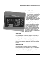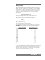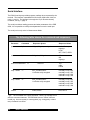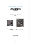
1
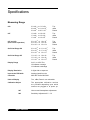
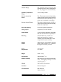
PDR 9000
OPERATION AND
MAINTENANCE MANUAL
Please Note:
MKS Instruments provides these documents as the latest version for the revision indicated.
The material is subject to change without notice, and should be verified if used in a critical
application.
PDR 9000
March 1999
PART #100010303 REV. A
HPSTM PDR 9000
Part # PDR9000X
__ __
Serial # __ __ __ __ __ __
Please fill in these numbers and
have them readily available when calling
for service or additional information.
(The part number can be found on
your packing slip, and both the part
number and serial number are located on
the bottom side of the housing.)
For more information or literature, contact:
Vacuum Products Group of MKS Instruments, Inc.
5330 Sterling Drive
Boulder, CO 80301 USA
Phone:
FAX:
303-449-9861
800-345-1967
303-442-6880
© 1999 by Vacuum Products Group of MKS Instruments, Inc. All rights reserved.
ALCONOX is a registered trademark of Alconox, Inc.
IgniTorr is a trademark of MKSTM Instruments of HPSTM, Inc.
Inconel is a registered trademark of Inco Alloys International, Inc.
Scotch-Brite is a trademark of 3M.
SensaVac is a registered trademark of MKS Instruments, Inc.
HPSTM PDR 9000
Table of Contents
Package Contents ..................................................................... 1
Symbols Used in this Manual .................................................... 1
Safety Precautions .................................................................... 2
Specifications ............................................................................ 4
Feature and Control Locations .................................................. 6
Make Accessory Connection ..................................................... 7
Controls and Indicators ............................................................. 9
Typical Applications for the PDR 9000 .................................... 10
About the HPSTM PDR 9000 .................................................... 11
Installing the PDR 9000 .......................................................... 12
Unpack the Controller .............................................................................. 12
Mount the Controller ................................................................................ 12
Connect the Vacuum Gauge .................................................................... 12
Attach the Cable ..................................................................................... 13
Check Supply Voltage ............................................................................. 13
Attach the Power Cord ............................................................................ 13
Operating the PDR 9000 ......................................................... 14
Turn Power On ........................................................................................ 14
Error Indicators ....................................................................................... 14
Restarting ............................................................................................... 14
Front Panel Controls ................................................................................ 14
CCG Gauge On/Off ................................................................................. 15
Hi Voltage LED ........................................................................................ 15
Autorange ............................................................................................... 15
Set Pt 1 .................................................................................................. 16
Set Pt 2 .................................................................................................. 16
Units ....................................................................................................... 17
Protect .................................................................................................... 17
Reset of Stored Values ........................................................................... 17
Reading Pressure ................................................................................... 18
Analog Output ......................................................................................... 19
Serial Interface ....................................................................................... 20
Using the PDR 9000 with Other Gases ................................... 21
Calibrate ................................................................................................. 21
Maintaining the PDR 9000 ...................................................... 22
Troubleshooting ....................................................................................... 22
Accessories/Part Replacement ............................................... 23
Product Warranty ..................................................................... 24
HPSTM PDR 9000
HPSTM PDR 9000
Package Contents
Before unpacking your PDR 9000 Controller, check all surfaces of the
packing material for shipping damage.
Please be sure your PDR 9000 package includes these items:
t Mounting Clips
t PDR 9000 Controller unit
t D-sub 15 accessory connector
t PDR 9000 User manual
t PDR 9000 Controller AC power cord
Inspect the PDR 9000 for visible damage. If it has been damaged in
shipping, notify the carrier immediately. Keep all shipping materials and
packaging for claim verification. Do not return the product to HPS
Vacuum Gauges
The 907 Convection Enhanced Pirani and the 903 Inverted
Magnetron transducer may be purchase from
MKS Instruments, Inc.
Vacuum Products Group
5330 Sterling Dr.
Boulder, CO. 80301
USA
(303) 449-9861
( Telephone
Toll-Free (800) 345-1967 (USA only)
Facsimile (303) 449-2003
Symbols Used in this Manual
The first two symbols below, that may be located on your PDR 9000,
identify critical safety concerns. They are used throughout this manual to
further define the safety concerns associated with the product.
The last two symbols identify other information in this manual that is
essential or useful in achieving optimal performance from the PDR 9000.
CAUTION: Refer to manual. Failure to heed message
could result in personal injury or serious damage to the
equipment or both.
Failure to heed message could result in damage
to the equipment.
F
Calls attention to important procedures, practices,
or conditions.
HPSTM PDR 9000
1
Safety Precautions
Safety Procedures and Precautions
The following general safety precautions must be observed during all phases of
operation of this instrument. Failure to comply with these precautions or with
specific warnings elsewhere in this manual violates safety standards of intended
use of the instrument and may impair the protection provided by the equipment.
MKS Instruments, Inc. assumes no liability for the customer’s failure to comply with
these requirements.
Properly ground the Controller.
This product is grounded through the grounding conductor of the
power cord. To avoid electrical shock, plug the power cord into a
properly wired receptacle before connecting it to the product input or output
terminals. A protective ground connection by way of the grounding
conductor in the power cord is essential for safe operation.
Upon loss of the protective-ground connection, all accessible conductive
parts (including knobs and controls that may appear to be insulating) can
render an electrical shock.
Do not substitute parts or modify instrument.
Do not install substitute parts or perform any unauthorized
modification to the instrument. Return the instrument to an MKS
Calibration and Service Center for service and repair to ensure that all
safety features are maintained.
Use proper electrical fittings.
Dangerous voltages are contained within this instrument. All
electrical fittings and cables must be of the type specified,
and in good condition. All electrical fittings must be properly
connected and grounded.
Use the proper power source.
This product is intended to operate from a power source that
applies a voltage between the supply conductors, or between
either of the supply conductors and ground, not more than that specified
in the manual.
22
HPSTM PDR 9000
Use the proper fuse.
Use only a fuse of the correct type, voltage rating, and current
rating, as specified for your product.
Do not operate in explosive environments.
To avoid explosion, do not operate this product in an explosive
environment unless it has been specifically certified for such operation.
Service by qualified personnel only.
Operating personnel must not remove instrument covers.
Component replacement and internal adjustments must be made by
qualified service personnel only.
Use the proper power cord.
Use only a power cord that is in good condition and which meets
the input power requirements specified in the manual.
Use only a detachable cord set with conductors that have a cross-sectional
area equal to or greater than 0.75 mm2. The power cable should be
approved by a qualified agency such as VDE, Semko, or SEV.
HPSTM PDR 9000
3
Specifications
Measuring Range
903
3.0 x10⁻¹⁰ to 5.0 x10⁻³
3.9 x10⁻¹⁰ to 6.4 x 10⁻³
3.9 x10⁻⁸ to 6.5 x 10⁻¹
Torr
mBar
Pascal
907
1.0 x10⁻³ to 1.0 x10³
1.3 x10⁻³ to 1.3 x10³
1.3 x10⁻¹ to 1.3 x10⁵
Torr
mBar
Pascal
907 and 903
(dual sensor operation)
3.0 x 10⁻¹⁰ to 1.0 x 10³
3.9 x 10⁻¹⁰ to 1.3 x 10³
3.9 x 10⁻⁸ to 1.3 x 10⁵
Torr
mBar
Pascal
Set Point Range 903
3.0 x 10⁻¹⁰ to 1.0 x 10⁻³
3.9 x 10⁻¹⁰ to 1.3 x 10⁻³
3.9 x 10⁻⁸ to 1.3 x 10⁻¹
Torr
mBar
Pascal
Set Point Range 907
1.0 x 10⁻² to 1.0 x 10³
1.5 x 10⁻² to 1.3 x 10³
1.5 x 10-0 to 1.3 x 10⁵
Torr
mBar
Pascal
Display Range
3x10⁻¹⁰ to 1000 Torr,
HI indicates overange
LO indicates underange
Display Resolution
2 digits with an exponent
Input to the PDR 9000
Controller
Analog signals from the
MKS 907 and/or MKS 903
Units of Display
Torr, mBar, Pascal: user selectable
Calibration Adjust
The appropriate calibration routines
are provided depending upon which
sensors are plugged in at power up.
44
907
Vacuum and Atmosphere adjustments
903
Sensitivity Adjustment 0.5 - 2.0
HPSTM PDR 9000
Vacuum Gauge
The controller can be used to read
pressure from a 907, a 903, or both gauges
can be plugged in simultaneously.
Operating Temperature
Range
+5 to +40 deg. Celsius
Process Control Set
Points
Two. These relays may be independently
assigned to either gauge when used with
both the 907 and 903. Alternatively, both
relays may be assigned to one gauge.
Process Control Relays
Two relays; contacts rated at 60 VDC or
30 VAC at 2 amp; the relays are internally
fused with 2 amp fuses.
Nonvolatile Memory
For all user specified parameters
Analog Output
Logarithmic, 0.5 volts / decade
Output Power
+15 at 0.35 amp, sufficient to operate the
MKS 907 and 903 RS-232 Input/Output
Mounting
The PDR 9000 may be used as a
bench-top instrument or it may be
mounted in an instrument panel. Clips
are provided for panel mounting.
RS-232
Output
Allows user to read pressure and set
points; 9600 baud, 8-N-1; available
through the accessory connector
Power
Requirement
90 - 265 VAC
47 - 65 HZ
Weight
0.9 lb. /0.4 kg
Repeatability
Approximately +- 5 %
Relative Humidity
80% maximum for temperatures less than
31 0 C, decreasing linearly to 50%
maximum at 400C
Altitude
2000 m (6561 ft) maximum
Insulation
Pollution Degree 2
CE Certification
EMC Directive
Safety Directive
HPSTM PDR 9000
5
Feature and Control Locations
3
l
4
l
5
l
6
l
1
l
2
l
3
l
4
l
5
l
6
l
7
l
66
CC Gauge On/Off (Setpoint Select) button
SELECT button
Pirani (Raise) button
CCG (Lower) button
Digital Display
Display Indicators
Mode Indicator
HPSTM PDR 9000
1
l
7
l
2
l
Make Accessory Connection
9 Pin Transducer Connector
15 Pin Accessory Connector
Power Connector
Fuses
The 15-pin D-sub Accessory Connector is on the rear panel of the PDR
9000 , see fig. 2, page 6. The connector has female pins; the mating
connector must have male pins. Mating D-sub 15 connectors are available
from many of the normal electronic sources. If you need help identifying a
source, please contact us
The following is the pin assignments for the 15 Pin Accessory Connector:
15-pin Accessory Connector
pin 1
pin 2
pin 3
pin 4
pin 5
pin 6
pin 7
pin 8
pin 9
pin 10
pin 11
pin 12
pin 13
pin 14
pin 15
set point #1 relay, normally closed
set point #1 relay, common
set point #1 relay, normally open
set point #2 relay, normally closed
set point #2 relay, common
set point #2 relay, normally open
Tx, RS-232; 9600-N-8-1
Rx, RS-232
ground, RS-232 and processed analog ground
Channel 2 buffered analog ground
Channel 2 buffered analog signal; 1K output
Channel 1 buffered analog ground
Processed analog output, 1K output, 0.5 volts/decade
High Voltage Disable (903) - low disables High Voltage
Channel 1 buffered analog signal; 1K output
Additional pin descriptions:
HPSTM PDR 9000
7
Pins 11 and 15 are the buffered analog output signals from the transducer
modules.
Pin 13 is the processed analog output signal that corresponds the to PDR
9000 display.
Pin 14 can be used to remotely disable high voltage to the CC sensor in
non Autorange mode. If the high voltage has been enabled with the front
panel push button, grounding this pin will remove the high voltage from the
CC. As soon as the ground signal is removed, high voltage returns.
The following is the pin assignments for the 9 pin transducer-connector:
pin 1
pin 2
pin 3
pin 4
pin 5
pin 6
pin 7
pin 8
pin 9
Analog input voltage (+) from transducer, Channel 1
Analog input voltage (+) from transducer, Channel 2
Analog input voltage (-) from transducer, Channel 2
HV Enable, Channel 2
+15 Volt Power supply (+) to both transducer modules
HV Enable, Channel 1
No Connection
Analog input voltage (-) from transducer, Channel 1
+15 Volt Power supply (-) to both transducer, modules
Note:
+15 volts can supply approximately 0.35 amp maximum
HV Enable (pins 4 & 6) only effective for the cold cathode module
88
HPSTM PDR 9000
Controls and Indicators
Normal Text describes Measurement
Mode operation. Italicized Text
indicates Setup Mode operation.
CC Gauge On/Off
(Setpoint Select) button
Turns On and Off the High Voltage to
the 903.
Allows user to assign set points to
either gauge in Setup Mode when used
with the 907 and the 903.
SELECT button
Places the controller in setup mode.
Allows the user to scroll through the
setup parameters that can be
adjusted, e.g. Set Points.
Pirani (Raise)
Selects the pressure from the MKS 907
to be displayed when the controller is
used with both sensors. Increments
parameter values in the Setup Mode.
CCG (Lower)
Selects the pressure from the MKS 903
to be displayed when the controller is
used with both sensors. Decrements
parameter values in the Setup Mode.
Digital Display
Display Indicators
MSD, LSD and sign with exponent
using 7-segment bright red LED, 10
mm high. The display is steady state
when indicating pressure
measurements. The display flashes
on and off with parameter values in
Setup Mode.
Bright red individual LEDS for
miscellaneous indicators
HPSTM PDR 9000
9
Typical Applications for the
PDR 9000
vv
vv
A cost-effective power supply and display unit for Series 903 and
Series 907 vacuum transducers.
Controlling transducers throughout a process pressure range, from
atmosphere through high vacuum.
vv
Starting and stopping system processes using relay set points.
vv
Controlling system pressure using the analog output as input to an
automatic pressure controller.
vv
vv
10
10
Digital readout of system process pressures.
Smooth linear pressure reading across overlap range of medium
and high vacuum gauges.
HPSTM PDR 9000
About the HPSTM PDR 9000
General Description
The MKS PDR 9000 Vacuum Gauge
Controller displays pressure from
3x10⁻¹⁰ to 1000 Torr, as measured from
the MKS 907 Convection Enhanced
Pirani and the MKS 903 Inverted
Magnetron Cold Cathode Gauge. The
PDR 9000 allows operation with either a
MKS 907, a MKS 903 or both gauges
may be used to provide continuous
measurement over 14 decades with
autoranging. The PDR 9000 precisely
measures the analog signal from either
transducer to determine pressure. When
autoranging, the PDR 9000 automatically
smooths the pressure reading over the
range of over lapping pressures. The
controller automatically determines which
sensors are plugged in at power up. The
PDR 9000 is housed in a 1/8 DIN enclosure
and is simple to operate. The PDR 9000
operates in two modes, a Set-Up Mode and a
Measurement Mode.
Set-Up Mode
In Set-Up mode, the user configures the operation of the controller. For
example, in Set-Up Mode the user assigns set point values, calibrates the
unit for specific gasses or selects autoranging for dual transducers. The
user cycles through the set up parameters by pressing the Select button.
The user adjusts the parameter values by pressing the Raise and Lower
buttons. The parameter values flash on and off on the digital display,
indicating the controller is in the set up mode. WHITE silk screening
identifies the Set-Up parameter indicators and controls on the PDR 9000
front panel.
Measurement Mode
In Measurement Mode, the controller displays the current pressure
measurement as a steady state (non-flashing) value on the digital display.
When two non-autoranging transducers are being controlled, the user can
select which transducer pressure reading is displayed be pressing the
Pirani or CCG button. YELLOW silk screening indicates the Measurement
Mode indicators and controls on the PDR 9000 front panel.
HPSTM PDR 9000
11
Installing the PDR 9000
Unpack the Controller
Carefully unpack the PDR 9000 Controller. The shipment includes these
components:
controller unit
s
s
power cord
s
mounting clips
s
D-sub 15 accessory connector
this instruction manual
s
If your controller does not have all of these items, contact MKS Instruments.
If anything appears to have been damaged in shipment, contact the
shipper. Transducers and cables are sold separately.
F
Do not plug the power cord in yet.
Mount the Controller
You can rest the controller unit on a bench, table top, or shelf, or you can
mount it in a rack or cabinet. The controller unit is housed in a standard
1/8 DIN box. If you are mounting the unit in a panel, the cutout dimensions
are 1.78 inch by 3.60 inch (45.2 mm by 91.4 mm), see fig. 3, page 7. One
mounting clip attaches to each of the sides of the controller unit. To attach
the clip, slide the beveled surfaces of the clip under the cutout on the side
of the box and push the clip toward the back of the unit.
Be sure to leave enough clearance at the back of the controller unit for easy
access to cable connections.
Connect the Vacuum Gauge
Make sure the transducer is securely connected to the vacuum system,
using good vacuum practice. The set point adjustments on the transducer
should be set to the minimum possible value. If necessary, refer to the 907
or 903 User's manual.
12
12
HPSTM PDR 9000
Attach the Cable
The cable has a 9-pin D-sub connector on one end, which plugs into
the PDR 9000.
Connect the 9-pin D-sub plug of the gauge cable to the 9-pin connector on
the back of the PDR 9000 controller unit. Push the plug onto the connector
until it is firmly in place. Tighten the retaining screws to make certain the
connector remains in place. Loose connections can cause faulty readings.
Check Supply Voltage
The PDR 9000 incorporates a universal power supply. This allows
the controller to operate on any input voltage from 90 VAC to 265 VAC ,
47 to 65 Hz.
Attach the Power Cord
Plug the power cord into the receptacle in the power module on the rear of
the PDR 9000 .
HPSTM PDR 9000
13
Operating the PDR 9000
Turn Power On
Plug the AC power end of the power cord into an electrical outlet. The
loudspeaker will “beep” and test all indicators while the controller executes
its self test. After being turned on, the instrument will go through the
following sequence:
s
s
s
s
s
“beeper”
indicators for TORR, MBAR, PASCAL ,PROTECT, VAC, ATM
9 LED indicators for set points and other functions
all digits will light, including decimal points
display shows the model number of the instrument, Pdr
display shows software version, e.g. 1.00
The PDR 9000 will go into normal operation and begin measuring
pressure.
Error Indicators
If neither transducer is connected, the display will show E01. The PDR
9000 can not operate two transducers of the same type. The display will
show E02 indicating two tranducers of the same type are pluged in.
Restarting
The PDR 9000 can be restarted with power applied by holding down the
Select button while simultaneously pressing both the Raise and Lower
buttons while the device is in Measurement Mode. This operation saves all
the current set up parameters, such as Set Points and the Protect voltage.
Front Panel Controls
The PDR 9000 allows flexible configuration of operation using simple
entry from the front panel buttons labeled SELECT, RAISE and LOWER.
Parameters which you may adjust are selected by scrolling through a list.
Only the parameters applicable to the transducers installed will be
displayed. Each time the SELECT button is pushed, the LED indicator
advances to the next parameter. The LED indicators will be lit to indicate
which parameter is being adjusted, and the digital display will flash to
indicate the value of the parameter being adjusted. Each push of a button
will give a short “beep” from the loudspeaker to confirm the button was
pushed. If you have reached the limit of adjustment or if the button push is
not allowed, the loudspeaker will give a long “beep”. Following is detail
description of the parameter selection and adjustment:
14
14
HPSTM PDR 9000
CC Gauge On/Off
This button allows the user to turn the CCG on and off from the front panel.
This is the only way to turn on high voltage to the cold cathode transducer
when not in autorange mode.
Hi Voltage LED
The Hi Volt LED is lit when the 903 high voltage is on. When the sensor is
off, OFF is displayed and the Hi Volt LED is extinguished.
Autorange
This parameter is available only when the MKS 907 and MKS 903 are both
installed.
When Autorange is turned OFF (default value), the transducers operate
independently and the pressure from either transducer is displayed by
pressing either the PIRANI or CCG push-button.
When Autorange is turned ON, the pressure display is automatically ranged
between the two transducers. A special smoothing algorithm is used in the
overlap region to allow continues measurement from 3x10⁻¹⁰ to 1000 Torr.
The smoothing algorithm operates between the pressures of 1X10⁻² to
8.5X10⁻⁵ Torr. The digital display always indicates the smoothed pressure.
The smoothed pressure reading is only valid for an Air/Nitrogen gas species
and if both transducers are monitoring the same pressure.
In Autorange mode, the cold cathode gauge is controlled by the pressure
measured by the pirani. The high voltage is applied to the CCG when the
pressure drops below 1X10⁻². High voltage is removed when pressure rises
above 1X10⁻². The user programmed protect voltage is not applicable in
Autorange mode.
The Autorange operation is intended for those applications that require
automatic on/off switching of the cold cathode transducer. Care must be
taken to ensure that the cold cathode is not exposed to a high pressure that
is not monitored by the pirani.
HPSTM PDR 9000
15
Set Pt 1
This sets the pressure at which the set point relay 1 will be energized. The
minimum value is OFF; this shuts the set point off. Use RAISE and LOWER to
set to the desired value.
Set point Range
903
907
3.0 x 10⁻¹⁰ to 1.0 x 10⁻³
3.9 x 10⁻¹⁰ to 1.3 x 10⁻³
3.9 x 10⁻⁸ to 1.3 x 10⁻¹
Torr
mBar
Pascal
1.0 x 10⁻² to 1.0 x 10³
1.3 x 10⁻² to 1.3 x 10³
1.3 x 10-0 to 1.3 x 10⁵
Torr
mBar
Pascal
Set points will not operate while the PDR 9000 is in Set-Up Mode.
Set Pt 2
This operates in the same manner as
SET PT
1 described above.
When operated with the 907 and 903, the set point can be
F
assigned to either sensor by using the Set Point select push-button while
the desired set point is selected. The selected transducer LED will light
indicating which transducer the set point is assigned. The unit can store up
to 4 set point assignments, one for each sensor for each set point. The set
point value used in Measurement Mode is the set point assigned to which
ever transducer (pirani or CCG) is selected when the Select button is
pressed to scroll to the next parameter setting.
16
16
HPSTM PDR 9000
Units
This allows selection of the displayed units. Press either the RAISE or LOWER
buttons scroll through Torr, mBar and Pascal. The indicators will be
alternately lit as the you scroll through the options. All numerics displayed
will be in the units selected. When the units are changed, the numeric
values will be changed leaving the actual pressure value unchanged.
Protect
This parameter adjusts the value at which the CCG will turn itself off. It
should be used to prevent the CCG from operating at pressures above
5x10⁻³ Torr. Operation above this pressure can result in false low pressure
readings due to roll back. The range for the parameter is between 1x10⁻⁵
Torr to 5x10⁻³ Torr. This function only works in non-autoranging mode.
F
Initial zero
When installing a transducer(s) for the first time, it is good practice to reset
the PDR 9000 internal settings. This will prevent errors in set up, e.g. if the
907 has not had its internal zero properly adjusted.
The 907 should be calibrated in accordance with the 907 User's manual
before corrections are made using the PDR9000 . The 903 has no user
adjustments.
Reset of Stored Values
This allows you to recover the factory settings for all stored values and
resets the set points and protect pressure to off. For a system that is far
out of calibration, the factory settings provide a good starting point for recalibrating or adjusting the gauge controller. To recover the factory
settings, power up the PDR 9000 while simultaneously pressing the Raise
and Lower push buttons. You will hear a few short ‘chirps’ from the
loudspeaker confirming the factory settings have been entered. The digital
display will show 'rST' to confirm the reset has been entered. After a reset,
the PDR 9000 is in the following state:
Set Points are OFF.
Protect Voltage is OFF.
Autorange is OFF.
Units set to Torr.
CCG calibration set to 1.0.
Pirani is uncorrected.
HPSTM PDR 9000
17
Reading Pressure
907
Display
Disconnect
or broken filament
<7x10⁻⁴ Torr
7x10⁻⁴ to 1100 Torr
>1100 Torr
OFF
903
< 3x10⁻¹⁰ Torr
not started, gauge not connected
3x10⁻¹⁰ to 5x10⁻³ Torr
>5x10⁻³ Torr
F
18
18
LO
MSD.LSDsignEXP
HI
Display
OP
MSD.LSDsignEXP
OFF
CCG turns itself off at pressures greater than 5x10⁻³ Torr or at the
user programmed protect voltage in non-autoranging mode. In
autoranging mode, the pirani turns the CCG on and off.
HPSTM PDR 9000
Analog Output
The Processed Analog Output is calculated from the value of the digital
display. The output is logarithmic, 0.5 volt/decade; the source impedance
for the output is 1 K ohm. The signal appears on pin 13 of the Accessory
Connector. It is only valid during Measurement Mode. In Setup Mode, it
remains at the last measured pressure value. The output voltage is
calculated from:
V=0.50*(log10(Pressure)+12)
where V is the Analog Output in volts; P is the pressure in Torr.
The pressure as a function of the Analog Output voltage is:
P=10(2V-12)
where P is pressure in Torr.
The units selected does not affect this output.
Some examples follow; because of normal tolerances in the electronics,
there may be minor differences in the values you observe compared to
those shown:
Display Information
OFF/OPEN/LO/EO1/EO2
1x10⁻¹⁰
1x10⁻⁹
1x10⁻⁸
1x10⁻⁷
1x10⁻⁶
1x10⁻⁵
1x10⁻⁴
1x10⁻³
1x10⁻²
1x10⁻¹
1x10 0
1x10+1
1x10+2
1x10+3
HI
Analog Output - volts
0.0
1.0
1.5
2.0
2.5
3.0
3.5
4.0
4.5
5.0
5.5
6.0
6.5
7.0
7.5
8.5
F
It two transducers are used and Autoranging is OFF, the processed
output will indicate the pressure from the same sensor that is currently
selected on the front panel display. If Autoranging is ON, the processed
output will provide a continues output from 1 to 7.5V.
HPSTM PDR 9000
19
Serial Interface
The RS-232 serial port provides pressure readings when requested by the
terminal. The interface is standard RS-232 format; 9600 baud, 8-bits, no
parity, 1 stop bit. The interface is through the 15-pin D-sub accessory
connector, see fig. 2, page 6.
The serial port allows reading pressure and other parameters of the PDR
9000; it is not possible to modify stored parameters over the serial port.
The serial port is only active in Measurement Mode.
The following table shows the command and responses
Parameter
Command
pressure
"p"
907_val,903_val,smooth_val<cr>
msd.lsdE+/-exp
nogauge
LO,HI
OFF, PROT, OPEN
sensor
"s"
CH1_xdcer,CH2_xdcer<cr>
907
903
nogauge
units of measurement
"u"
Response Syntax
Units<cr>
Torr
mBar
Pascal
relay 1 status
"1"
SP1_val,status,xdcer
1 indicates relay energized
msd.lsdE+/-exp,0,907
msd.lsdE+/-exp,1,907
msd.lsdE+/-exp,0,903
msd.lsdE+/-exp,1,903
relay 2 status
"2"
SP2_val,status,xdcer
1 indicates relay energized
msd.lsdE+/-exp,0,907
msd.lsdE+/-exp,1,907
msd.lsdE+/-exp,0,903
msd.lsdE+/-exp,1,903
version
"v"
model,version
PDR,verx.xx
F
The commands are a single character. There is no carriage return
after the command character. The PDR 9000 returns "%Error" when an
invalid (e.g. incorrect syntax) or unrecognized (e.g. wrong parity or baud
rate) command is received.
20
20
Response Values
HPSTM PDR 9000
Using the PDR 9000 with other
Gases
Calibrate
The parameters available will depend upon the transducers installed
Pirani
ATM
The PIRANI LED, CALIBRATE LED and ATM indicator will light. This parameter
allows the atmospheric reading of the 907 to be adjusted to a reference
pressure. Use RAISE and LOWER to set to the desired value.
Do not use the ATM adjustment on the 907 unless the controller is unable
to set the correct pressure. Refer to the 907 manual before making any
these adjustments.
to support the widest range of gases, the PDR 9000 does
F Innotorder
limit the upper range of atmospheric calibration.
Pirani
VAC
The PIRANI LED, CALIBRATE LED and VAC indicator will light.
This parameter allows the vacuum reading of 907 to be adjusted. The
adjustment should be made by pumping the tranducer to below 1x10⁻⁵ Torr
and adjusting the reading to 0.0x10⁻³ Torr . Use RAISE and LOWER to set to
the desired value.
Do not use the VAC adjustment on the 907 unless the controller is unable to
set the correct pressure. Refer to the 907 manual before making this
adjustment.
CCG
The CCG LED, AND CALIBRATE LED indicators will light. This parameter is a
multiplier between .5-2. Use RAISE and LOWER to set to the desired value. It
may be used to correct for small variations between sensors or changes in
sensitivity due to variations in the gas type.
HPSTM PDR 9000
21
Maintaining the PDR 9000
Trouble shooting
If the self-test fails, run the self-test again by turning the power off and
then on again. If it fails again, call MKS Instruments, Vacuum Products
Group in Boulder, CO.
If fuses burn out, check to see that the proper voltage has been supplied to
the power input module.
If fuses burn out repeatedly call MKS Instruments, Vacuum Products Group
in Boulder, CO.
If the digital display consistently shows LO, OFF or HI, it may be that one of
the internal power supply protection devices has removed power to the
transducer. You may check this by measuring the voltage at the connector
or cable for the unaffected gauge. Since power for both gauges use the
same protection device, either connector will show the power supply
voltages. Normal range for the voltages are 14.5 to 15.5 volts. +15 may be
measured on the red wire; power return is on the black wire. If the power
supply protection has shut the power off, you will typically measure less
than 4 volts on the affected supply.
If you verify that either power supply is shut off, remove power from the
transducer for a few minutes to allow the protection device to reset itself.
The protection device does not need to be replaced; it is a reusable
thermal fuse.
You may wish to determine the cause for the loss of power supply voltage
before applying power again. The PDR 9000 will protect itself if it finds
excessive power draw again.
It is normal for the PDR 9000 to feel warm to touch along the left side of
the case.
If the trouble appears to be related to either the MKS 907 Convection
Enhanced Pirani or MKS 903 Cold Cathode Gauge, please refer to the
appropriate users manual which is included with the transducer.
22
22
HPSTM PDR 9000
Accessories / Part Replacement
If you need to return the gauge controller to MKS Instruments for service,
first contact Customer Service at MKS Instruments Vacuum Products
Group to obtain an ERA number. Then pack the instrument securely and
place the ERA number on the outside of the package where it is easily
seen. Use the original packaging if it is available. If you do not have
appropriate packing materials, a commercial packing and shipping firm
can provide them.
Changing Fuses
The controller contains two fuses. Both fuses are held in the fuse assembly
that is part of the power module located on the back panel of the controller.
To change fuses, unplug the line cord from the power entry module at the
rear of the PDR 9000; locate the fuse block immediately below the line cord
socket. Press the tab of the fuse assembly and withdraw the fuse assembly
1
from the power module.
Turn the fuse assembly around so that the fuses are facing you. Check
both fuses; replace the burnt-out fuse with a fuse of the appropriate rating .
Reinsert the fuse assembly into the power module; push it in until the ears
click into place.
Replacement fuse type: 5 mm X 20 mm, Fast-blow 1 amp
Manufacturer
Bussman
Little fuse
Fuse Type
GDB-1A
217 001
Schematic Diagrams
Because of the proprietary nature of our products, we do not supply
schematic diagrams or software listings. If you have any problem with
operation or interface to any of our products, please contact us; we will do
everything we can to serve your needs.
HPSTM PDR 9000
23
Product Warranty
Extent of the Warranty
MKS Instruments, Inc. (MKS), warrants the HPSTM PDR 9000 and its accessories to be free from
defects in materials and workmanship for one (1) year from the date of shipment by HPSTM or authorized
representative to the original purchaser (PURCHASER). Any product or parts of the product repaired or
replaced by HPSTM under this warranty are warranted only for the remaining unexpired part of its one (1)
year original warranty period. After expiration of the applicable warranty period, the PURCHASER shall be
charged HPSTM’ current prices for parts and labor, plus any transportation for any repairs or replacement.
ALL EXPRESS AND IMPLIED WARRANTIES, INCLUDING THE IMPLIED WARRANTIES OF
MERCHANTABILITY AND FITNESS FOR A PARTICULAR PURPOSE, ARE LIMITED TO THE WARRANTY
PERIOD. NO WARRANTIES, EXPRESS OR IMPLIED, WILL APPLY AFTER THIS PERIOD.
Warranty Service
The obligations of HPSTM under this warranty shall be at its option: (1) to repair, replace, or adjust the
product so that it meets applicable product specifications published by HPSTM or (2) to refund the purchase
price.
What Is Not Covered
The product is subject to above terms only if located in the country of the seller from whom the product
was purchased. The above warranties do not apply to:
I. Damages or malfunctions due to failure to provide reasonable and necessary maintenance in
accordance with HPS operating instructions.
II. Damages or malfunctions due to chemical or electrolytic influences or use of the product in
working environments outside the specification.
III. Fuses and all expendable items which by their nature or limited lifetime may not function for a year. If
such items fail to give reasonable service for a reasonable period of time within the warranty period
of the product; they will, at the option of HPSTM, be repaired or replaced.
IV. Defects or damages caused by modifications and repairs effected by the original PURCHASER or
third parties not authorized in the manual.
Condition of Returned Products
HPSTM will not accept for repair, replacement, or credit any product which is asserted to be defective by
the PURCHASER, or any product for which paid or unpaid service is desired, if the product is contaminated
with potentially corrosive, reactive, harmful, or radioactive materials, gases, or chemicals.
When products are used with toxic chemicals, or in an atmosphere that is dangerous to the health of
humans, or is environmentally unsafe, it is the responsibility of the PURCHASER to have the product
cleaned by an independent agency skilled and approved in the handling and cleaning of contaminated
materials before the product will be accepted by HPSTM for repair and/or replacement.
In the course of implementing this policy, HPSTM Customer Service Personnel may inquire of the
PURCHASER whether the product has been contaminated with or exposed to potentially corrosive,
reactive, harmful, or radioactive materials, gases, or chemicals when the PURCHASER requests a return
authorization. Notwithstanding such inquiries, it is the responsibility of the PURCHASER to ensure that no
products are returned to HPS which have been contaminated in the aforementioned manner.
Other Rights and Remedies
I. These remedies are exclusive. HPSTM SHALL NOT BE LIABLE FOR CONSEQUENTIAL DAMAGES,
FOR ANTICIPATED OR LOST PROFITS, INCIDENTAL DAMAGES OR LOSS OF TIME, OR OTHER
LOSSES INCURRED BY THE PURCHASER OR BY ANY THIRD PARTY IN CONNECTION WITH
THE PRODUCT COVERED BY THIS WARRANTY, OR OTHERWISE. Some states do not allow
exclusion or limitation of incidental or consequential damage or do not allow the limitation on how
long an implied warranty lasts. If such laws apply, the limitations or exclusions expressed herein
may not apply to PURCHASER.
II. Unless otherwise explicitly agreed in writing, it is understood that these are the only written
warranties given by HPSTM. Any statements made by any persons, including representatives of
HPSTM, which are inconsistent or in conflict with the terms of the warranty shall not be binding on
HPSTM unless reduced to writing and approved by an authorized officer of HPSTM.
III. This warranty gives PURCHASER specific legal rights, and PURCHASER may also have other rights
which vary from state to state.
IV. For HPSTM products sold outside of the U.S., contact your MKSTM representative for warranty
information and service.
Warranty Performance
To obtain warranty satisfaction, contact the following: MKSTM Instruments HPSTM Products, Inc., 5330
Sterling Drive, Boulder, CO 80301, USA, at phone number (303) 449-9861. You may be required to present
proof of original purchase.
24
24
HPSTM PDR 9000
Notes
HPSTM PDR 9000
25
26
26
HPSTM PDR 9000
SensaVac® PDR 9000
SensaVac® PDR 9000