1
AVFL Vent Free Fireplace System
Installation & Operating Instructions
Models: AVFL42NTSC & AVFL42PTSC
WARNING: If the information in this
manual is not followed exactly, a fire or
explosion may result causing property
damage, personal injury or loss of life.
•
•
•
Do not store or use gasoline or other
flammable vapors and liquids in the
vicinity of this or any other appliance.
WHAT TO DO IF YOU SMELL GAS
– Do not try to light any appliance.
– Do not touch any electrical switch; do
not use any phone in your building.
– Leave the buildling immediately.
– Immediately call your gas supplier from
a neighbor's phone. Follow the gas
supplier's instructions.
– If you cannot reach your gas supplier,
call the fire department.
Installation and service must be performed
by a qualified installer, service agency or
the gas supplier.
This is an unvented gas-fired heater. It uses air
(oxygen) from the room in which it is installed.
Provisions for adequate combustion and ventilation air must be provided. Refer to Page 7.
INSTALLER: Leave this manual with the appliance.
CONSUMER: Retain this manual for future
reference.
20305467 5/14 Rev. 1
AVFL Vent Free Fireplace
CONTENTS
Thank you and congratulations on your purchase of an
Vermont Castings Group Fireplace.
PLEASE READ THE INSTALLATION AND OPERATION INSTRUCTIONS BEFORE USING THE APPLIANCE!
IMPORTANT: Read all instructions and warnings carefully before starting installation.
Failure to follow these instructions may result in a possible fire hazard and will void the warranty.
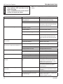
Important Safety Information .................................... 3
To Turn Off Gas to Appliance.................................. 18
Building Code Information ......................................... 4
Signature Command® System Operation ................ 19
Features ................................................................. 19
Battery Installation .................................................. 19
System Configuration/Setup ................................... 19
Cold Climate Option ............................................... 19
Functions/Operation ............................................... 21
Product Features ......................................................... 5
AVFL42 Controls ...................................................... 5
Gas Specifications & Orifice Size ............................. 5
Gas Pressures .......................................................... 5
Fireplace and Framing Dimensions .......................... 6
Pre-installation Information ........................................ 7
Getting Started ......................................................... 7
What You Will Need .................................................. 7
Planning the Installation ........................................... 7
Adequate Combustion and Ventilation Air ................ 7
Fireplace Location .................................................... 8
Clearances & Height Requirements ......................... 9
Fireplace Installation ................................................. 10
Secure Fireplace to Framing .................................. 10
Finishing Material ................................................... 10
Noncombustible Facing Installation...........................................10
Connect the Gas .................................................... 11
Check Gas Pressure .............................................. 12
Electrical Installation................................................. 13
Wiring Junction Box ............................................... 13
Signature Command® Wiring Diagram ................... 14
Final Installation ........................................................ 15
Installation of Air Deflection Glass .......................... 15
Glass Only Placement ............................................ 15
Glass & Optional Stone Kit Placement ................... 15
Placement of Optional Logs ................................... 16
Touch Screen Remote Control Operation ............... 22
Troubleshooting ...................................................... 27
Maintenance and Cleaning ....................................... 28
Flame Appearance ................................................. 28
Check the Pilot Flame ............................................ 28
Check Burner Flame Appearance .......................... 28
Cleaning and Servicing .......................................... 29
Operating Information ............................................. 29
Troubleshooting ........................................................ 30
Signature Command® System ................................ 31
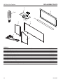
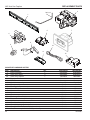
Replacement Parts .................................................... 32
Firebox ................................................................... 32
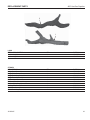
Logs ........................................................................ 33
Stones .................................................................... 33
Signature Command® System ................................ 34
Optional Accessories ................................................ 35
Limited Lifetime Warranty Policy ............................. 39
Operating Instructions .............................................. 17
For Your Safety Read Before Lighting .................... 17
Turning On Unit ...................................................... 18
2
20305467
AVFL Vent Free Fireplace
IMPORTANT SAFETY INFORMATION
OWNER
Please leave these instructions with the appliance.
Please retain these instructions for future reference.
WARNING
INSTALLER
• Any change to this heater or its controls can be dangerous.
• Improper installation or use of the heater can cause serious injury or death from fire, burns,
explosion or carbon monoxide poisoning.
• Do not allow fans to blow directly into the fireplace. Avoid any drafts that alter burner flame
patterns.
• Do not use a blower insert, heat exchanger insert or other accessory, not approved for use
with this heater where applicable.
1. Due to high temperatures, the appliance should be
located out of traffic and away from furniture and
draperies.
2. Children and adults should be alerted to the hazard
of high surface temperature and should stay away
to avoid burns or clothing ignition.
3. Young children should be carefully supervised when
they are in the same room with the appliance.
4. Do not place clothing or other flammable material
on or near the appliance.
5. Any safety screen or guard removed for servicing
an appliance, must be replaced prior to operating
the heater.
6. Installation and repair should be done by a qualified service person. To prevent malfunction and/or
sooting, an unvented gas heater should be cleaned
before use and at least annually by a professional
service person. More frequent cleaning may be
required due to excessive lint from carpeting,
bedding materials, etc. It is imperative that control
compartments, burners and circulating air passageways be kept clean.
7. WARNING: Any change to this heater or its controls
can be dangerous.
8. Unvented gas heaters are a supplemental zone
heater. They are not intended to be the primary
heating appliance.
9. CARBON MONOXIDE POISONING: Early signs of
carbon monoxide poisoning are similar to the flu with
headaches, dizziness and/or nausea. If you have these
signs, obtain fresh air immediately. Have the heater
serviced as it may not be operating properly.
10. The installation must conform with local codes or, in
the absence of local codes, with the National Fuel
Gas Code, ANSI Z223.l/NFPA54.
11. This unit complies with ANSI Z21.11.2 Unvented
Heaters, latest edition.
20305467
12. Do not install the heaters in a bathroom or bedroom.
13. Correct installation of the ceramic fiber logs, proper
location of the heater, and annual cleaning are necessary to avoid potential problems with sooting. Sooting,
resulting from improper installation or operation, can
settle on surfaces outside the fireplace. Refer to log
placement instructions for proper installation.
14. Avoid any drafts that alter burner flame patterns. Do not
allow fans to blow directly into fireplace. Do not place
a blower inside burn area of firebox. Ceiling fans may
create drafts that alter burner flame patterns. Sooting
and improper burning will occur.
15. Caution: Candles, incense, oil lamps, etc. produce
combustion byproducts including soot. Vent-free
appliances will not filter or clean soot produced by
these types of products. In addition, the smoke and/
or aromatics (scents) may be reburned in the vent-free
appliance which can produce odors. It is recommended
to minimize the use of candles, incense, etc. while the
vent-free appliance is in operation.
16. This is an unvented gas-fired heater. It uses air
(oxygen) from the room in which it is installed. Provisions for adequate combustion and ventilation air must
be provided. Refer to Page 7.
17. This heater shall not be installed in a room or space
unless the required volume of indoor combustion air is
provided by the method described in the National Fuel
Gas Code, ANSI Z223.1/NFPA 54, the International
Fuel Gas Code or applicable local codes.
18. Keep room area clear and free from combustible materials, gasoline and other flammable vapors and liquids.
19. Unvented gas heaters emit moisture into the living
area. In most homes of average construction, this
does not pose a problem. In houses of extremely
tight construction, additional mechanical ventilation is
recommended.
20. During manufacturing, fabricating and shipping, various
components of this appliance are treated with certain
oils, films or bonding agents. These chemicals are not
3
AVFL Vent Free Fireplace
21.
22.
23.
24.
25.
4
harmful but may produce annoying smoke and smells
as they are burned off during the initial operation of the
appliance; possibly causing headaches or eye or lung
irritation. This is a normal and temporary occurrence.
The initial break-in operation should last two to three
hours with the burner at the highest setting. Provide
maximum ventilation by opening windows or doors to
allow odors to dissipate. Any odors remaining after this
initial break-in period will be slight and will disappear
with continued use.
Input ratings are shown in BTU per hour and are for
elevations up to 2,000 feet. For elevations above 2,000
feet, input ratings should be reduced 4 percent for each
1,000 feet above sea level. Refer to the National Fuel
Gas Code.
The appliance and its appliance main gas valve must
be disconnected from the gas supply piping system
during any pressure testing of that system at test
pressures in excess of 1⁄2 psig (3.5 kPa).
The appliance must be isolated from gas supply piping
system by closing its equipment shutoff valve during
any pressure testing of the gas supply piping system at
test pressures equal to or less than 1⁄2 psig (3.5 kPa).
Do not use this room heater if any part has been under
water. Immediately call a qualified service technician
to inspect the room heater and to replace any part of
the control system and any gas control which has been
under water.
Never burn solid fuels in a fireplace where a unvented
room heater is installed.
IMPORTANT SAFETY INFORMATION
This appliance may be installed in an aftermarket, permanently located, manufactured
(mobile) home, where not prohibited by local
codes.
This appliance is only for use with the type of
gas indicated on the rating plate. This appliance
is not convertible for use with other gases.
BUILDING CODE INFORMATION
Adhere to all local codes or, in their absence, the latest
edition of THE NATIONAL FUEL GAS CODE ANSI Z223.1
or NFPA54 which can be obtained from:
American National Standards Institute, Inc.
1430 Broadway
New York, NY 10018
or
National Fire Protection Association, Inc.
Batterymarch Park
Quincy, MA 02269
20305467
AVFL Vent Free Fireplace
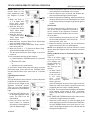
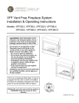
PRODUCT FEATURES
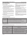
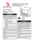
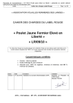
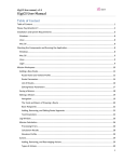
AVFL42 CONTROLS
GAS SPECIFICATIONS & ORIFICE SIZE
MODEL
FUEL
AVFL42NTSC
NAT.
AVFL42PTSC
LP.
MAX. INPUT
(BTU/h)
MIN. INPUT
(BTU/h)
ORIFICE
SIZE
37,000
24,500
2.20 mm
36,000
28,500
#55
NOTE: For LP models an external regulator is required
to reduce supply pressure to a maximum of 13" w.c.
GAS PRESSURES
Thermocouple
Module
Command Center
Control Board
FP3020
NATURAL
PROPANE (LP)
Inlet Minimum
5.0" w.c.
11.0" w.c.
Inlet Maximum
10.5" w.c.
13.0" w.c.
Regulator Pressure
Setting
3.5" w.c.
10" w.c.
Pilot Regulator
3.5" w.c.
—
AC Module
Figure 1 –
AVFL42 Controls (Control Access Door Shown Open)
20305467
5
AVFL Vent Free Fireplace
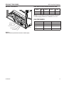
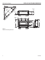
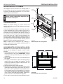
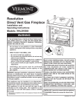
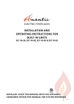
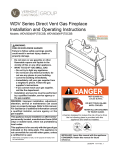
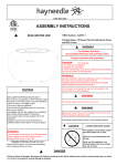
FIREPLACE AND FRAMING DIMENSIONS
Minimum
Rough
Depth
1/2" (13 mm)
or 5/8" (16 mm)
13"
(330 mm) 13 1/2"
(343 mm)
B\
zn
"(
17
51
m
m
)
(8 34Z
76 \x
m "
m
)
44" (1118 mm)
Rough Opening Width
68
Z
48C\v" (1238 mm)
48C\v" (1238 mm)
Minimum
Rough
Height
32"
(813 mm)
37 1/2" (953 mm)
28"
(711 mm)
15 3/16"
(386 mm)
13 1/4"
(337 mm)
32"
(813 mm)
6 1/16"
(154 mm)
39 3/4" (1010 mm)
Figure 2 –
Fireplace and Framing Dimensions
6
43" (1092 mm)
2 1/4"
(57 mm)
4 5/8"
(118 mm)
20305467
PRE-INSTALLATION INFORMATION
AVFL Vent Free Fireplace
GETTING STARTED
PLANNING THE INSTALLATION
Check your packing list to verify that all listed parts have
been received. You should have the following:
• Unvented gas heater
• Two (2) anchoring screws
• Installation/operating instructions
• 5" non-combustible board
• 2" x 32" deflector glass
• Two (2) bags fireglass
• Twelve (12) 20 watt bulbs
• One (1) 100 watt bulb
• TSFSC remote control
In planning the installation for the fireplace it is necessary
to determine where the unit is to be installed and whether
optional accessories are desired. Gas supply piping should
also be planned. The following steps represent the normal
sequence of installation. Each installation is unique, however, and might require a different sequence.
Carefully inspect the contents for shipping damage. If any
parts are missing or damaged, immediately inform the
dealer from whom you purchased the appliance. Do not
attempt to install any part of the appliance unless you
have all parts in good condition.
WHAT YOU WILL NEED
You must have the following items available before proceeding with installation:
• External regulator (for propane/LPG only)
• Manual shutoff valve
• Piping which complies with local codes
• Sediment trap
• Phillips head screwdriver
• Tee joint.
• Pipe sealant approved for use with propane/LPG
(Resistant to sulfur compounds)
• Pipe wrench
WARNING
• Where curtains, furniture, clothing, or
WARNING
Do not install the heater:
Gloves are recommended when handling
ceramic fiber logs to prevent skin irritation
from loose fibers. Logs are fragile — handle
with care.
other flammable objects are less than
36" from the front of the heater.
• In high traffic areas.
• In windy or drafty areas.
20305467
1. Position fireplace in desired location. Refer to the Fireplace Location (page 8, Figure 3) and Clearances and
Height Requirements (page 9, Figures 4 and 5) sections
and Fireplace and Framing Dimensions (page 6, Figure
2) illustration found in this manual.
NOTE: Be sure all packing material has been removed
from under the unit.
2. Install following the instructions found in this manual.
3. Field wire main power supply to junction box. Refer to
the Electrical Installation section (page 13). (Electrical
connections should only be performed by an experienced, licensed certified service person).
4. Plumb gas line. Refer to the Connect the Gas (page
11, Figure 7) section found in this manual. (Gas
connections should only be performed by an experienced, licensed/certified service person).
5. Complete finish wall material and/or surround.
ADEQUATE COMBUSTION AND VENTILATION AIR
This heater shall not be installed in a confined space or
unusually tight construction unless provisions are provided
for adequate combustion and ventilation air.
The National Fuel Gas Code, (ANSI Z223.1/NFPA54),
defines a confined space as a space whose volume is less
than 50 cubic feet per 1,000 BTU per hour (4.8m3 per kw) of
the aggregate input rating of all appliances installed in that
pace, and an unconfined space as a space whose volume
is not less than 50 cubic feet per 1,000 BTU per hour (4.8
m3 per kw) of the aggregate input rating of all appliances
installed in that space. Rooms communicating directly with
the space in which the appliances are installed, through
openings not furnished with doors, are considered a part
of a confined space.
Unusually tight construction is defined as construction
where:
a. walls and ceilings exposed to the outside atmosphere
have a continuous water vapor retarder with a rating of
1 perm (6 x 10¹¹ kg per pa/sec-m2) or less with openings
gasketed or sealed, and
b. weather stripping has been added on openable windows
and doors, and
7
AVFL Vent Free Fireplace
PRE-INSTALLATION INFORMATION
c. caulking or sealants are applied to areas such as joints
around window and door frames, between sole plates
and floors, between wall-ceiling joints, between wall
panels, at penetrations for plumbing, electrical and gas
lines and other openings.
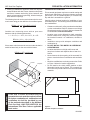
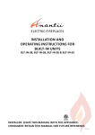
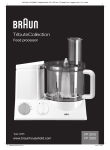
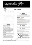
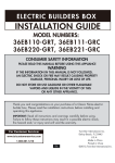
FIREPLACE LOCATION
The following formula can be used to determine the maximum heater rating per the definition of unconfined space:
Carefully select the best location for installation of your
unvented fireplace. The following factors should be taken
into consideration.
BTU/Hr = (L1 + L2) Ft x (W) Ft x (H) Ft
50
This unvented gas heater requires no outside venting and
burns cleanly and efficiency. As a zero-clearance unvented
gas heater, it can be installed against (or recessed into)
any wall that is accessible to a gas line.
•
Consider two connecting rooms with an open area
between, with the following dimensions:
•
L1 = 151/2 Ft., L2 = 12 Ft., W = 12 Ft., H = 8 Ft.
BTU/Hr = (151/2 + 12) x (12) x (8)
50
•
If there were a door between the two rooms the calculation
would be based only on the room with the heater.
•
•
BTU/Hr = (15 /2) x (12) x (8)
50
1
•
Counter
•
Fireplace
•
Clearance to side wall, ceiling, woodwork and window
or other combustibles. Refer to Clearance and Height
Requirements section on Page 9. Minimum clearances
to combustibles must be maintained.
Location must not be affected by drafts caused by
kitchen exhaust fans, ceiling fans, return air registers
for forced air furnaces / air conditioners, windows or
doors.
Installation must provide adequate ventilation and
combustion air.
DO NOT INSTALL THIS MODEL IN A BEDROOM
OR BATHROOM.
Location should be out of high traffic areas and
away from furniture and draperies due to heat from
firebox.
Never obstruct the front opening of the unvented fireplace or restrict the flow of combustion and ventilation
air.
Minimize modifications to existing construction. Refer
to Figure 3 below for location suggestions.
Do not install in the vicinity where gasoline or other
flammable liquids may be stored. The unvented firebox must be kept clear and free from the combustible
materials.
H
WARNING
W
8
If the area in which the heater may be
operated does not meet the required volume
for indoor combustion air, combustion and
ventilation air shall be provided by one
of the methods described in the National
Fuel Gas Code, ANSI Z223.1/NFPA 54, the
International Fuel Gas Code or applicable
local codes.
Figure 3 –
Possible Fireplace Locations
FP3029
20305467
AVFL Vent Free Fireplace
PRE-INSTALLATION INFORMATION
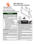
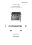
Ensure that minimum clearances shown in Figures 4 and
5 are maintained. Left and right clearances are determined
when facing the front of the firebox.
Follow these instructions carefully to ensure safe installation. Failure to follow these requirements may create a
fire hazard.
Sidewall Clearances — The clearance from the inside of
the appliance to any combustible adjacent wall should not
be less than 6". Figure 4
Ceiling Clearance — The ceiling or any other combustible
material must be at least 36" from the firebox opening.
Figure 4
Back Wall Clearance — The appliance may be placed
against a combustible back wall.
WARNING
CLEARANCES AND HEIGHT REQUIREMENTS
The dimensions shown in Figures 4 and
5 are minimum clearances to maintain
when installing this heater. Left and right
clearances are determined when facing the
front of the heater.
Follow these instructions carefully to
ensure safe installation. Failure to follow
instructions exactly can create a fire
hazard.
Floor Clearance — The fireplace may be installed directly
on a combustible floor or a raised platform of an appropriate
height. Do not place fireplace on carpeting, vinyl, tile or
other soft floor coverings. It may, however, be placed on flat
wood, plywood, particle board or other hard surfaces. Be
sure fireplace rests on a solid continuous floor or platform
with appropriate framing for support so that no cold air can
enter from under the firebox.
Mantel clearances — Must meet the clearance requirements detailed in Figures 4 and 5.
Wall
Stud
36" Minimum
From Opening
12" Max.
Depth
Insulation
Board
12"
Standoff
6"
21/2"
28"
21/2" Max
Depth
28" Min.
From Opening
23"
18"
Top of Fireplace
Opening
SIDE VIEW
6" Min.
FP3007
18" Min.
From Opening
FP3006
Figure 4 –
Sidewall and Ceiling Clearances
1"
Fireplace
Opening
156O"
356O"
256O"
456O"
3"
45°
5"
6"
TOP VIEW
FP3008
Figure 5 –
Mantel Clearances
20305467
9
AVFL Vent Free Fireplace
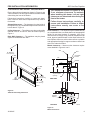
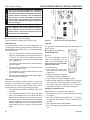
FIREPLACE INSTALLATION
SECURE FIREPLACE TO FRAMING
The fireplace must be secured to the framing studs as
shown in Figure 6. Use four (4) screws to attach fireplace
to framing. The side nailing flanges are 1⁄2" or 5⁄8" to accommodate different wall thickness.
Framing
Members
NOTE
Noncombustible Material
5”
Never install combustible materials over
front face of fireplace.
FINISHING MATERIAL
Nailing
Flange
Screws
NOTE: Any remote wiring (i.e. remote control, wall
switch), must be done prior to final finishing to avoid costly
reconstruction.
Only noncombustible materials (i.e. brick, tile, slate, steel,
or other materials with a UL fire rating of Zero) may be
used to cover the black painted face of the appliance. It is
permissible to bring combustible wall board to the top of
the standoffs on the top and to the wall board stand-offs
on the sides of the unit. A 300°F minimum adhesive may
be used to attach facing materials to the black surface. If
joints between the finished wall and the fireplace surround
are sealed, a 300°F minimum sealant material (General
Electric RTV103 or equivalent) must be used.
NOTE: Fireplace may be installed on top of framing or
platform constructed of combustible materials which do
not protrude beyond the face.
Nailing
Flange
Nailing
Flange
Screws
Figure 6 –
Secure Fireplace to Framing Studs
FP3009
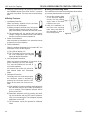
NONCOMBUSTIBLE FACING INSTALLATION
CAUTION: The noncombustible wall board supplied with
this unit can be damaged if dropped or struck. Handle
with care.
1. Using drywall screws secure noncombustible board to
the two brackets on top of unit. IMPORTANT: To avoid
cracking the board, pre-drill holes prior to securing to the
unit/framing.
2. Wipe any debris or dust from the noncombustible board
and drywall.
3. It is highly recommended to prime the facing using a
quality primer prior to taping and mudding. This will
ensure proper adhesion of both the tape and mud. The
supplied board is very porous.
4. Tape the seams using a mesh type tape.
5. Mud seams as normal. We recommend using a product
call Durabond high strength compound for the first coat.
This product can be purchased at any hardware store.
Follow manufacturer's recommendations for curing the
mud. NOTE: Depending upon the final finishing method,
use a minimum rated 300 degree sealant, drywall compound or thin set to seal the side and top joints.
6. Prime wall for a second time for proper adhesion of paint.
10
43"
MOUNTING POINTS
5"
32"
44"
Figure 6A –
Noncombustible facing installation
20305467
AVFL Vent Free Fireplace
FIREPLACE INSTALLATION
NOTICE: A qualified gas appliance installer must connect
the heater to the gas supply. Consult all local codes.
WARNING
This appliance is equipped for either natural or
propane gas. Field conversion is not permitted.
WARNING
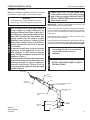
CONNECT THE GAS
CHECK GAS TYPE: The gas supply must
be the same as stated on the heater’s rating
plate. If the gas supply is different, DO NOT
INSTALL THE HEATER. Contact your dealer
for the correct model.
Always use an external regulator for all propane/LPG heaters only, to reduce the supply tank pressure to a maximum
of 13" w.c. This is in addition to the internal regulator in the
heater valve.
When tightening the joint to the valve, hold the valve
securely to prevent movement.
Test all gas joints from the gas meter to the heater valve for
leaks using a gas analyzer or soap and water solution after
completing connection. DO NOT USE AN OPEN FLAME.
WARNING
Use new black iron or steel pipe. Internally
tinned copper or copper tubing can be
used per National Fuel Code, section 2.6.3,
providing gas meets hydrogen sulfide limits,
and where permitted by local codes. Gas
piping system must be sized to provide
minimum inlet pressure (Listed on Data
Plate) at the maximum flow rate (BTU/hr).
Undue pressure loss will occur if the pipe
is too small.
A manual shutoff valve must be installed
upstream of the appliance. Union tee
and plugged 1⁄ 8" NPT pressure tapping
point should be installed upstream of the
appliance. Figure 7
A sediment trap should be installed upstream
to prevent moisture and contaminants from
passing through the pipe to appliance
controls and burners. Failure to do so
could prevent the appliance from operating
reliable. Figure 7
Connecting directly to an unregulated
propane/LP tank can cause an
explosion.
WARNING
WARNING
IMPORTANT: Loosen the pipe adapter on the flex tube
before installing to the system piping.
DO NOT USE OPEN FLAME TO CHECK
FOR GAS LEAKS.
To Fireplace
Pipe
Coupling
Pipe
Stainless
Flexible Tube
Locations Pressure Tapping
Point Installation
Gas Supply
Inlet
Manual Shutoff
Valve
Tee Joint
Sediment
Trap
Figure 7 –
Gas Connection
20305467
3" Min.
Pipe Nipple
Cap
FP2447
11
AVFL Vent Free Fireplace
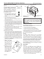
CHECK GAS PRESSURE
FIREPLACE INSTALLATION
Test Port 'A'
Figure 8
Check the gas pressure with the appliance burning and
the control set to HIGH.
Open control access door at bottom front of unit to find
valve and regulator referred to below.
The valve regulator controls the burner pressure which
should be checked at the pressure test point.
Turn captured screw counterclockwise two or three turns
and then place tubing to pressure gauge over test point.
Use test point “A” closest to gas inlet. After taking pressure
reading, be sure and turn captured screw clockwise firmly
to reseal. Do not over torque. Check for gas leaks.
FP3036
Figure 8 –
Pressure Test Point Location – Signature Command® Valve
12
20305467
AVFL Vent Free Fireplace
ELECTRICAL INSTALLATION
Label all wires prior to disconnection when
servicing controls. Wiring errors can cause
improper and dangerous operation. Verify
proper operation after servicing.
CAUTION
WARNING
1. Before installing, wire the receptacle into an electrical
circuit. This should be done before framing the fireplace. Wire with minimum 60° C wire in accordance
with prevailing codes.
2. Remove the external junction box cover by removing
the screw from the right side of the outside firebox wall.
Junction box was installed at the factory.
3. The junction box cover has a factory installed “romex”
style strain relief connector. After connecting the wires,
route the wire leads through this connector.
Electrical connections should only be performed
by a qualified licensed electrician. Main power
supply must be turned off before connecting to
the main electrical power supply or performing
service.
WARNING
WIRING JUNCTION BOX
Electrical Grounding Instructions:
This appliance is equipped with a three-prong
(grounding) plug for your protection against
shock hazard and should be plugged directly
into a properly grounded three prong receptacle.
IMPORTANT: Always check local building codes. This installation must comply with local regulations as well as
the National Electric Code.
For vent free SC System, the unit will continue to burn
during power loss to AC only with batteries installed.
Without power, the unit will shut down without batteries
installed but can be started with fresh batteries installed
from the Command Center.
120V AC
60Hz
Factory Supplied
Not Supplied
Junction Box
Figure 9 –
Junction Box Wiring Diagram
20305467
13
AVFL Vent Free Fireplace
ELECTRICAL INSTALLATION
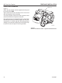
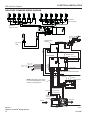
SIGNATURE COMMAND WIRING DIAGRAM
Front Row
20w x 6 Lamps
Back Row
20W x 6 Lamps
A/C MODULE
WHITE
BLACK
WHITE
Opt. Blower
WHITE
BLACK
BLACK
PLUG-IN
CONNECTOR
TO JUNCTION BOX
IN FIREPLACE
GREEN
Thermocouple
Module
Black
Thermocouple
Pilot
Yellow
Top Lamp
100w
Orange
RF Receiver
ON/OFF Button
Control Board
Black / Thermopile
Red / Thermopile
Sensor
{
Plug in
Connector
Optional
Blower
Hearth
Light { White
Black
White
Black
Top Light { White
Black
Ignitor / Sparker
Green
Plug-in Connector
Control Board to Command Center
Red
OFF/LO
NOTE: Wall switch wires must
be connected together if a wall
switch is not being used.
Ground
Plug-in Connector
Stepper Motor to
Control Board
LED
ON/HI
Master Switch
Command Center
DC Power/Green
Plug-in Connector
Control Board to
Solenoid
Gas Out
Gas In
Pilot Gas Tubing
Figure 9 –
Signature Command® Wiring Diagram
14
Valve
FP3010
20305467
AVFL Vent Free Fireplace
FINAL INSTALLATION
INSTALLATION OF AIR DEFLECTION
GLASS
NOTE: The 32" deflector glass must be installed prior
to placing any fireglass or stone media on the burner.
To install the air deflection glass simply place the tabs
located at the bottom of the glass into the slots at either
end of the burner floor, in front of the burner ports. The
glass should stand upright, neither leaning forward nor
backward.
GLASS ONLY PLACEMENT
NOTE: Two (2) bags of glass are supplied with the fireplace.
Both bags may be used to cover the entire floor and burner.
We advise against using additional glass as too much can
cut off the proper amount of air the burner needs to burn
cleanly. This may cause sooting.
Air Deflection Glass Placement (before)
Burner Surface
1. Spread glass evenly in one layer over the entire floor
and burner. It is important to not have the glass too thick
on ported area (single layer only).
2. Turn burner on and adjust glass over ported areas to
achieve an even, clean flame.
GLASS AND OPTIONAL STONE KIT PLACEMENT
1. For best results, spread glass evenly over the entire
floor and burner making sure the glass is not too thick
over the burner ports (single layer only). Figure 10A.
2. Place the stones randomly in front of and behind the
burner. CAUTION: Do not allow stones to sit directly
on burner or in flame. Figure 10A and 10B.
3. Turn burner on and adjust glass over the ported area
to achieve an even, clean flame. Page 28, Figure 29
Air Deflection Glass Placement (after)
Rear Vent
Examples of
Stone Placement
Figure 10A –
Air Deflection Glass and Stone Placement
20305467
15
AVFL Vent Free Fireplace
FINAL INSTALLATION
WARNING
The positioning of the logs is critical to
the safe and clean operation of this heater.
Sooting and other problems may result if the
logs are not properly and firmly positioned
in the appliance. Never add additional logs
or embellishments such as pine cones,
vermiculite or rock wool to the heater. Only
use the logs supplied with the optional log
kit (AVFL42DLS).
Failure to position the parts in accordance
with diagrams below or to use only
parts specifically approved for this
heater may result in property damage or
personal injury.
Figure 10B –
Stone Placement
PLACEMENT OF OPTIONAL LOGS
WARNING: Turn off fireplace and allow to cool completely before beginning installation.
Kit Contents:
• Two (2) ceramic fiber driftwood logs
• Four (4) log support pin brackets
• Eight (8) #8 bracket mounting screws
NOTE — Do not handle logs with your bare hands. Always
wear gloves to prevent skin irritation from ceramic fibers. After handling the logs, wash your hands with soap
and water to remove any traces of fibers.
NOTE: Prior to installing the log set, you must first install the
pin brackets on the burner. Fireglass and the air deflection
glass should only be installed after the pin brackets are in
place. The logs must then be placed in the unit after the
fireglass and air deflection glass. If the optional logs are
added after the air deflection glass and fireglass are in use,
move the fireglass away from the areas in Figure 11 and
install the support brackets, then arrange fireglass evenly
across burner again.
1. Mount the four log support
pin brackets using mounting holes and screws provided in locations indicated
in Figure 12. Note that the
front log can be mounted
in two different positions.
The pin brackets can be
moved to accommodate
the preferred log placement.
2. Place the large rear log
(#1) by aligning the holes
in the bottom of the log Figure 11 –
with the two pins at the Log Pin Assembly
back of the burner. Figure 13A.
Pin placement
Log #1 (Rear)
Figure 12 –
Alternative Log Placement
16
Pin placement
Log #2 (Front)
Option 1
Pin placement
Log #2 (Front)
Option 2
Air Deflection
Glass
20305467
AVFL Vent Free Fireplace
OPERATING INSTRUCTIONS
3. Place the front log (#2) by aligning the holes in the
bottom of the log with the two pins at the front of the
burner. The front log may be placed in one of two po-
Figure 13A–
Front Log Placement
sitions on the burner depending on which two pin set
locations are used.
Figure 13B –
Alternative Front Log Placement
WARNING
FOR YOUR SAFETY READ BEFORE LIGHTING
If you do not follow these instructions
exactly, a fire or explosion may result
causing property damage, personal
injury or loss of life.
A. This appliance is equipped with an ignition device which automatically lights the pilot. Refer
to the instructions.
B. BEFORE OPERATING smell all around the appliance area for gas. Be sure to smell next to
the floor because some gas is heavier than air and will settle on the floor.
WHAT TO DO IF YOU SMELL GAS:
• Do not attempt to light any appliance.
• Do not touch any electric switch; do not use any phone in your building.
• Immediately call your gas supplier from a neighbor's phone. Follow the gas supplier's
instructions.
• If you cannot reach your gas supplier, call the fire department.
C. Use only your finger to push in the master switch. Never use tools. If the switch will not function
by hand, do not try to repair it. Call a qualified service technician. Force or attempted repair
may result in a fire or explosion.
D. Do not use this appliance if any part of it has been under water. Immediately call a qualified
service technician to inspect the appliance and to replace any part of the control system and
any gas control that has been under water.
20305467
17
AVFL Vent Free Fireplace
OPERATING INSTRUCTIONS
TURNING ON UNIT
1. STOP! Read the safety information on Page 17.
2. This appliance is equipped with an ignition device which automatically lights the burner. Do not try
to light the burner by hand.
3. With five (5) minutes to clear out any gas. Then smell for gas, including near the floor. If you smell
gas, STOP! Follow "B" in the safety information on Page 17. If you do not smell gas, go to next
step.
4. Press the master switch to the "ON" (-) position. Within eight (8) seconds it will beep once. This
indicates the system is ready.
5. Press "ON " button. Sparker will spark and pilot flame will light.
6. Once pilot flame is established, the main burner flame will light automatically.
7. If the pilot will not stay lit after several tries, turn the master switch to "OFF" and call your service
technician or gas supplier.
OFF
OFF
ON
Master
Switch
ON
Command Center
Pilot
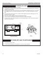
TO TURN OFF GAS TO APPLIANCE
1. Turn master switch to "OFF".
2. Turn off all electrical power to the appliance if service is to be performed.
18
20305467
AVFL Vent Free Fireplace
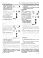
SIGNATURE COMMAND SYSTEM OPERATION
FEATURES
To Thermopile
RF Receiver
ON/OFF
Command Center
To Sensor
To Sparker
• Easy Access Function Operation and System Configuration
• Operation Confirmation/Fault Diagnostic Indications
(LED/Buzzer)
• ON/OFF/HI/Med/Low Operation
• Optional Wall Mounting
Control Board
• Electronic Ignition
• Pilot Lockout safety feature
• Electric Power Regeneration from Thermopile to save
•
•
•
•
•
•
battery
6-hour Automatic Shut Down Option
Standing Pilot/Intermittent pilot Conversion
Previous settings Restoration Ability (Memory Off)
Uninterrupted Operation During Power Outage (Automatic Battery Backup)
ON/OFF RF Remote Receiver
Optional Transmitter Learn Capability
AC Module (Requires TSFSC Remote)
• Easy Snap-on Design
• Embedded Compact 120 VAC Adapter with Auto Battery Back up Feature
• Remote Controlled 3-step Blower, Lighting, and On/
Off Auxiliary AC Outputs
Transmitter – TSFSC
•
•
•
•
•
•
•
•
Three Flame Height Settings
Low battery Indication for Transmitter
Child Proof Lock-out
LCD Backlight
Security Codes 16
Countdown 6 hr Timer
Standard Thermostatic Control Mode
Smart Mode® Thermostat (Auto Flame & Blower
Modulation)
• Three Brightness Settings for Lights
• On/Off Auxiliary
BATTERY INSTALLATION
The Command Center uses four (4) "AA" batteries as
back up for power outages. The system can operate for
approximately six (6) months on battery power.
To Install Batteries (not included):
1. Press down the battery door tabs and pull out to remove
battery door.
20305467
NG/LP
Conversion
To Command Center
CONTROL BOARD
ON
LED
To Stepper Motor
To Valve
Master Switch
OFF
AC Module
Battery Door
COMMAND CENTER
FP1917
Figure 14 –
Signature Command® System Components
2. Install the batteries as indicated on Command Center.
3. Close battery door by snapping in place.
4. When the four (4) batteries are installed the system will
operate without power.
5. The batteries should be replaced when the LED indicates low battery or at least once a year.
SYSTEM CONFIGURATION/SETUP
All System configuration/setup is done on the Command
Center.
NOTE: When using On/Off wall switch, the switch must be
in the ON position to perform all configuration set ups at
the command center.
COLD CLIMATE OPTION
Choose the Mode That Best Suits Your Needs
The Signature Command® System is designed to operate
in either Standing Pilot or Intermittent Pilot mode.
• The Standing Pilot Mode is best for colder climates
when the pilot must remain on continuously to prevent
condensation and ensure reliable operation.
• The Intermittent Pilot Mode is ideal for maximum efficiency, igniting the pilot only when needed to start your
fireplace, lowering fuel consumption and reducing your
carbon footprint.
Either mode benefits from the instantaneous battery backup, so you never have to worry about a power outage.
19
AVFL Vent Free Fireplace
SIGNATURE COMMAND SYSTEM OPERATION
NOTE: The Signature Command® System comes standard
in the Intermittent Pilot mode, so you must follow the instructions below to switch to Standing Pilot Mode if needed.
Intermittent/Standing Pilot Setup (Default intermittent)
1. Holding the ON button on the Command Center while
turning on the master switch will toggle between standing pilot and intermittent pilot.
2. After the above operation, one beep (for standing pilot) or two beeps (for intermittent pilot) will be given as
confirmation.
Six-hour Safety Shutdown Option (Default ON)
1. The system comes preset from the factory with a six
(6) hour shutdown from its last command of operation.
This is done to prevent the fireplace from continuing to
operate if unattended. You may disable this feature if
you wish.
NOTE: By disabling this feature, your fireplace may continue to operate unattended.
2. When the master switch is in the ON position (“-”), pressing the ON button and the OFF button on the Command
Center simultaneously will toggle between enabling and
disabling the six-hour shutdown option.
3. After the above operation, one beep (for enabling the
six-hour shutdown option) or two beeps (for disabling
the six-hour shutdown option) will be given as confirmation.
FUNCTION
Remote Transmitter Learn Function (Default OFF)
1. The RF receiver button located on the Control Board
must be in the on position before the learn function can
begin. Use paper clip to depress button. One beep for
RF receiver ON or two beeps for RF receiver OFF will be
given as confirmation. Refer to Figure 40 for location.
2. After the RF receiver is on, holding the OFF button on
the Command Center while turning on the master switch
will activate the learn function for the transmitter.
3. After the above operation, two beeps will be given and
the green LED on the Command Center will flash for
10 seconds.
4. During the 10 seconds, press the OFF button on a
transmitter to learn. Another two beeps will be given
to confirm a successful learning. Refer to transmitter
instructions for remote operations.
Shutting Off the Standing Pilot (Temporary Shut Off)
To shut off the standing pilot for service or summer shut
down, press and hold the ON button on the Command
Center for 3 seconds when the master switch is in the ON
position (“-”) and the main burner is off.
Note: Pilot will resume the next time system is turned
on.
Key Combinations for System Settings
NOTE: When On/Off wall switch is used, it must be in the
On position to perform all system setups.
OPERATION
Intermittent/Standing Pilot Hold the ON button while turning the master switch
Setup
(It will beep once for standing pilot, twice for intermittent pilot.)
Standing Pilot
Temperature Shutoff
Hold the ON button for 3 seconds (when the master switch on
the main burner is off.)
RF Remote Receiver
ON/OFF
Push the RF receiver ON/OFF button on the control board.
(It will beep once for On and twice for OFF.)
Learn Remote
Transmitter
Hold the OFF button while turning on the master switch
(Listen for two beeps, then press any button on the remote.)
6-Hour Safety
Shutdown Setup
20
Press the ON button and OFF button simultaneously
(It will beep once for ON, twice for OFF.)
DEFAULT SETTING
INTERMITTENT
PILOT
RF OFF
ON
20305467
AVFL Vent Free Fireplace
SIGNATURE COMMAND SYSTEM OPERATION
FUNCTIONS/OPERATION
(from the Command Center)
Turning on the fireplace
1. Turn on the master switch and wait for a beep.
2. Press the ON button on the Command Center or turn
on wall switch. Pilot will light and burner will come on
High setting or last memory setting (See Turning Off
Fireplace below). For memory feature.
Pilot Safety Lockout Function
1. If the pilot doesn’t light after sparking for 30 seconds, pilot
trial lockout happens. The LED on the Command Center
flashes Green once every 2 seconds, until reset.
2. If the pilot flame is lost during normal operation, the
system will try three (3) times to relight after three (3)
failures, flame loss lockout happens. The LED on the
Command Center flashes Red-Green once every 2
seconds, until reset.
3. Turning the master switch on the Command Center to
the off position, then ON again will reset the system.
Flame Height Control
1. Press the ON button (on the Command Center) once to
turn on the main burner with maximum flame height.
2. Press the OFF button to decrease flame height. The first
two presses will decrease the flame height to medium
and low.
3. The third press on OFF will turn off the main burner. In
standing pilot configuration, the pilot will stay; in intermittent pilot configuration, the pilot will be shut off.
Turning the Off Fireplace
There are three ways to turn off the fireplace.
1. Flip the master switch to the off (“O”) position. (This will
turn the entire system OFF.)
2. Press the OFF button to Medium, Low, then Off.
3. Hold the OFF button anytime for three seconds or by
turning off the wall switch. These two commands of
OFF are (Memory Off) the system will remember all last
settings before turning off. The next time the fireplace is
turned on, all settings will resume. To reset, change to
the desired settings and shut off by using the Memory
Off commands and the system will be reset to those
new settings.
NOTE: After turning off there may be up to a two (2)
minute delay before the burner can be relit. There will be
three (3) red flashes if the on button is pressed before
the safety control is automatically reset.
Command Center Operations:
The following functions are available on the Command Center.
FUNCTION
OPERATION
Power Up
Flip the master switch to ON ("_") position to power up the system.
Fireplace ON
Press the ON button on the Command Center or turn on wall switch.
Fireplace OFF
Flip the master switch to the OFF ("o") position OR press the OFF button 3
times OR for Memory Off, hold the OFF button 3 seconds, or turn off wall switch.
Flame Height Up
Flame Height Down
Press the ON button once to turn on the fireplace with maximum flame height.
Press the OFF button to lower the flame height to Medium and Low.
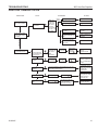
Self Diagnostics Chart:
The Command Center has a self-diagnostic LED enabling you to troubleshoot problems and potentially avoid a service
call. Please refer to the chart below for indicator reference.
FAULT
LED INDICATOR
Conversion Cover Missing
One RED (1 time)
Spark Fail
Two RED (1 time)
No Sensor Signal
Three RED (1 time)
Pilot Lockout – trial
One GREEN, every 2 seconds until manual reset
Pilot Lockout – flame loss
One RED-GREEN every 2 seconds until manual reset
Low Battery
One RED every 10 seconds continuously
No or Low Thermopile Power
Two RED every 10 seconds continuously
Learning
GREEN flashes every 1 second for 10 seconds
AC Power On
GREEN solid
Pressure Switch Failed (Power Vent only)
One RED every 2 seconds until manual reset
20305467
21
Menus
Logo
Bar
Function Areas of the LCD Display
Figure 15 shows the display of the TSFSC LCD.
Information Bar
The information bar shows the room temperature, the
“sending signal” radio icon, the low battery indication icon,
the child-proof icon, and the flame icon. This area doesn’t
have touch buttons.
• The room temperature will always be shown after
•
•
•
•
power-up. It displays the room temperature from 40
°F to 99 °F. “Lo” and “HI” will be displayed when the
room temperature is lower than 40°F or higher than
99°F, respectively.
The radio icon will be shown when the transmitter is
sending a signal.
The low battery indication icon will be shown when
the battery voltage is low.
The child-proof icon will be shown when the childproof mode is activated.
The flame icon indicates the current flame height –
Off, Low, Medium and High
Touch Area
The touch area contains all touch buttons to control the
transmitter. It consists of two categories: menus and adjustment arrows. The blue LED backlight lights up for 8
seconds when any of the touch buttons is pressed.
• The menus include TIMER, THERMO, LIGHT, FAN
•
22
and AUX.
The adjustment arrows include ON/up and OFF/
down. Their default function is to adjust the flame
height. When a button from the menu is pressed,
the ON/up and OFF/down buttons will temporarily
become adjustment controls for the selected item.
When the adjustment is done, the ON/up and OFF/
down buttons go back to flame height controller
again.
Adjustment
Controls
Turn appliance OFF (at the Master Switch) if
you are away from your house for an extended
period of time. Never leave anything on top of
the surface of the transmitter.
Touch Area
Due to the sensitive temperature monitoring
components in the transmitter, it is necessary
to allow the transmitter to stabilize to room temperature before accurate room temperatures
are displayed. If the transmitter is activated
from a severe cold condition, allow 15 minutes
for accurate temperature readings to appear on
the LCD display.
Information
Bar
NOTE
TOUCH SCREEN REMOTE CONTROL OPERATION
WARNING
AVFL Vent Free Fireplace
Figure 15
Function Areas of the LCD Display
Logo Bar
The Logo Bar contains the brand logo: Signature Command® System.
Initialization and Setting up
Installing Batteries:
Figure 16
The remote transmitter has two
battery compartments, one on
each end of the transmitter. Always change all four (4) batteries at the same time.
Battery
Door
Tabs
To install batteries,
1. Press down the battery door
tab and pull out to remove the
Figure 16
battery door.
2. Install the batteries as indicated inside the battery compartments.
3. Close the battery door by snapping in place.
4. When all four batteries are installed, the transmitter
will initialize for 5 seconds and then is ready for use.
5. The batteries should be replaced every 12 months or
when the low battery icon indicator is displayed.
Changing Temperature Unit
When batteries are installed in the transmitter,
1. All available icons on the LCD will be turned on then
be cleared.
2. The LCD will display temperature unit: °F. Use ON ∆
to toggle the units between °F and °C within the first 5
seconds.
3. The transmitter enters Manual Mode
4. The LCD displays room temperature with the chosen
unit.
20305467
AVFL Vent Free Fireplace
TOUCH SCREEN REMOTE CONTROL OPERATION
ON
Setting Privacy Code on Transmitter:
Figure 17
OFF
The remote transmitter privacy code
is preset in factory. In the event of
activation or interference from other
nearby transmissions, change the
code using the following procedures
(learn function must be performed after changing the code):
Performing Learn Function
1. The RF receiver button on the control board in the fireplace must be in the on position before the learn function can begin. Figure 16. With the Command Center
master switch in the ON position, use paper clip to depress the recessed button on Control Board, one beep
for RF receiver ON or two beeps for RF receiver OFF.
2. Holding the OFF button on the Command Center while
turning on the master switch will activate the learn
function for the transmitter.
3. After the above operation, two beeps
will sound and the
green LED on the
Command Center will
flash for 10 seconds.
4. During the 10 seconds, press the OFF
button on the transmitter to learn. Another two beeps will be
sound confirming a
successful learn function. Figure 19
Figure 18
20305467
FP2650
Battery Door
Figure 19 –
Command Center
WARNING
1. Press the ON/arrow button and
the TIMER button at the same
time to enter privacy code setup
models.
Figure 17
2. The setup display is shown in the
figure. The four digits on the top
stand for the privacy code. The default values of the
four digits will be all “0.”
3. The first digit will be flashing upon entering the setup
mode. Push the ON button to toggle its value between
“0” and “9,” and push the “OFF” button to jump to the
next digit. The next digit will then start flashing and the
first one stops flashing. Set up the four digits to your
choice between “0” and “9.”
4. After setting up all the four digits, push “OFF” to finish
the process and return to the previous mode.
5. The Signature Command® control board then needs to
re-learn the new setting.
Master Switch
LED
Front Panel Bezel
(Optional)
Do not use two (2) or more remote control systems in the same area with the same privacy
code setting, as they will communicate with
each other. This may cause the appliances to
malfunction.
Resetting the transmitter:
If the transmitter is not working properly, reinstall the batteries to reset the transmitter.
1. Pull out at least one of the batteries.
2. Press any key on the screen to discharge.
3. Wait for 10 seconds and reinstall the batteries.
Pushing and holding any key for more than 10 seconds
until the display refreshes will also reset the transmitter.
Functions and Operations
General:
The TSFSC Remote Control has four (4) operating
modes: Manual, Timer, Thermostatic and Smart Mode.
The control system can be set to temperature range between 45° F and 90° F. The flame height can be adjusted
in the manual, timer and thermostatic mode. The Smart
Mode will automatically adjust flame height according to
the difference between Set and Room temperatures.
The transmitter will operate the remote receiver from 1
foot to a maximum of 30 feet. The distance is reduced
when batteries are low.
Manual Mode
Figure 20
In this mode, the TIMER button and the THERMO button will only display “TIMER” and “THERMO,” respectively without showing the time and the SET temperature.
Pressing the ON/up and OFF/down buttons will change
the flame height if none of the menu buttons (TIMER,
THERMO, LIGHT, FAN, AUX) are pressed and flashing.
1. Press the ON/up button to turn on the fireplace. The
flame icon on the LCD displays High.
23
AVFL Vent Free Fireplace
TOUCH SCREEN REMOTE CONTROL OPERATION
2. Press the OFF/down button
to decrease the flame height
and turn off the fireplace.
When the OFF/down button
is pressed for three times,
the flame icon changes form
High to Medium, to Low,
then to Off.
3. If the OFF button is held for
more than 3 seconds at any
flame height, the fireplace
will be turned off and the
flame icon disappears.
4. Sliding up and down on the
arrow buttons can also turn
on or turn off the fireplace.
5. If the fireplace is shut off us- Figure 20
ing the above methods in 3
and 4, all the settings will be
remembered and will be resumed next time the fireplace is turned on (Memory Off).
Timer Mode
Figure 21
Press the TIMER button to enter timer mode. The fireplace
will stay on for a period of time
as specified by the timer and
then be shut off by the transmitter when the timer counts down
to zero.
1. When the TIMER button is
pressed, the Set Time appears in the frame of the button and flashes.
2. Use ON/up and OFF/down
to increase or decrease
the Set Time in 15 min. increments, between 0:00 to Figure 21
6:00. Sliding up and down
on the arrow buttons will increase or decrease the Set Time in 1 hour increments.
3. Push the TIMER button again to confirm the Set Time,
the transmitter sends an ON signal to turn on the fireplace.
4. The flashing stops and the ON/up and OFF/down buttons become flame height controller again. The flame
height will then stay as set up by the ON/up and OFF/
down buttons.
5. The TIMER button can be used when the transmitter
is in Manual Mode or in Thermostat Mode. In both
modes, the fireplace will be shut down completely
when the timer counts down to zero.
6. To exit Timer Mode:
24
a. Push and hold the TIMER button for 3 seconds or
b. Use the OFF/down buttons to decrease the Set
Time to zero or
c. Slide down on the arrow buttons to exit TIMER
mode and shut off the fireplace.
Thermostat Mode
Figure 20
Press the THERMO button to
set the transmitter in thermostat mode. The transmitter will
automatically turn on the fireplace when the room temperature is below the set temperature and turn off the appliance
when the room temperature
is above the set temperature
within one degree.
1. When the THERMO button
is pressed, the Set temperature appears in the frame of
the button and flashes.
2. Use ON/up and OFF/down
to increase or decrease the Figure 22
Set temperature in 1 degree
increments, between 45 degrees and 90 degrees.
Slide up and down on the arrow buttons will increase
or decrease the Set Temperature in 10 degrees increments.
3. Press the THERMO button again to confirm the Set
Temperature. The transmitter will send out an On
signal or an Off signal depending on the relationship
between the Set temperature and the Room temperature.
4. The flashing stops and the ON/up and OFF/down buttons become flame height controller again. The flame
height will then stay as set up by the ON/up and OFF/
down buttons.
5. To exit Thermostat Mode:
a. push and hold the THERMO buttons for 3 seconds
or
b. slide down on the arrow buttons to exit Thermostat
mode and shut off the fireplace.
Smart Mode Option for Thermostat Mode
Figure 23
Press and hold the THERMO button and the ON/UP button at the same time for 3 seconds to toggle between
Smart Mode and the regular Thermostat Mode. The icon
“Smart Mode” will appear under the Set Temperature. The
transmitter will automatically adjust the flame height according to the difference between the Set temperature
and the Room temperature. There is no manual flame
height adjustment. The fan speed will also automatically
adjust if turned on.
20305467
TOUCH SCREEN REMOTE CONTROL OPERATION
NOTE: there will a 10
second delay for the
flame adjustment when
the fireplace is turned
on.
Smart
Mode
Icon
1. When Set Temp. is
3° F or higher than
Room Temp., flame
height will be on High.
2. When Set Temp. is 2°
F higher than Room
Temp., flame height
will be on Medium.
3. When Set Temp. is 1°
F higher than Room
Figure 23
Temp., flame height
will be on Low.
4. When Set Temp. is equal to Room Temp., flame height
does not change (stays on low).
5. When Set Temp. is lower than Room Temp., the fireplace will be shut off.
6. When Set Temp. is 1° F higher than Room Temp.,
again the flame height will be on Low.
7. The fan speed follows the flame height, if the fan is
turned on.
To exit Smart Mode and shut off the fireplace;
a. push and hold the THERMO buttons for 3 seconds,
or
b. press the OFF button
or
c. slide down on the arrow buttons.
To shut off the Smart Mode option and return to regular
thermostat mode, press and hold the THERMO button
and the ON/UP button at the same time for 3 seconds
again.
Light Brightness Control
Figure 24
The light brightness control function is used to adjust the
brightness of the light bulbs connected to the AC module on the
Signature Command® System.
There are four light brightness
levels defined: Off, Low, Medium,
High
1. Press the LIGHT button to enter the light brightness control
mode. The LIGHT icon will
start flashing.
2. Press the On/up and OFF/
down buttons to increase/
decrease the light brightness
(Off-Low-Medium-High).
Figure 24
20305467
AVFL Vent Free Fireplace
3. Press the light button again to confirm the setting. The
new setting will be transmitted to the receiver.
4. After the signal is sent, the On/up and Off/down buttons become flame height controller again.
5. When the light button is flashing, slide up and down on
the arrow buttons will turn the light brightness to HIGH
or Off directly without pressing the light button again to
confirm.
AUX Control
The AUX control function is used to turn on or
turn off the auxiliary component connected to
the AC module of the Signature Command®
System. Press the AUX button to turn on or turn
off the auxiliary.
1. When the auxiliary is turned on, the icon will
become solid text and the “ON” icon will appear below the “AUX” icon.
2. When the auxiliary is turned off, the icon will become
hollow text and the “ON” icon will disappear.
NOTE: Some fireplaces use the AUX function to control
options within the fireplace. Refer to fireplace manual for
operation.
Setting up Blank Screen or Constant Display in Idle
Figure 23
There is an option
to set up how the
LCD displays and
functions when the
transmitter is in
idle. There are two
choices:
1. A) Mode. When
the transmitter is
in idle, the icons
in the “touch
area”
(timer,
Figure 25
thermostat,
blower, light and
AUX) will disappear, as shown in the figure on the left.
When any of the touch buttons is pressed, those icons
will appear and are ready to operate (default).
2. B) Mode. The transmitter always displays all available
icons showing current status of timer, thermostat,
blower, light and AUX as shown in the figure on the
right.
Press TIMER and THERMO buttons at the same time for
3 seconds to toggle between A) and B).
1. When the current setting is A), touch any place in the
touch area to bring up the icons then press TIMER button and THERMO button at the same time for 3 seconds. The backlight will flash once to indicate that the
setting has changed to B).
25
AVFL Vent Free Fireplace
TOUCH SCREEN REMOTE CONTROL OPERATION
2. When the current setting is B), pressing TIMER button
and THERMO button at the same time for 3 seconds
will switch to A) Mode. The touch area icons will disappear.
Safety Features
1. Low Battery Detection
When low battery condition occurs, the transmitter will turn off the fireplace.
A) Battery voltage is checked every one minute.
When the battery voltage is low, the LCD displays a low battery icon which will exist in all modes.
B) The transmitter will not operate with low battery
voltage. Change the batteries before the batteries
become too weak for normal operations.
2. Power On Initialization
After the power-on initialization, the transmitter sends
a signal to turn off the fireplace.
3. Thermal Shutdown
When the ambient temperature is more than 99°F, the
transmitter will turn off the fireplace.
A) The LCD will display “HI.”
B) The Transmitter will not function until
the room temperature has dropped
below 99 degree Fahrenheit.
4. Low Temperature Condition
When the ambient temperature is less than 40 degrees Fahrenheit, the LCD will display
“LO,” and NO SIGNAL will be sent to
turn on the appliance.
All functions still remain the same for
both Manual Mode and Thermostat
Mode.
5. Child-proof Protection
The child-proof icon will be shown when
the child-proof mode is activated by
pressing the ON button and the OFF
button at the same time for three seconds.
A) Enter childproof mode by pressing and holding both
the ON button and the OFF button simultaneously for 3 seconds. The Childproof indicator will be
shown on the LCD.
B) Deactivate childproof mode by pressing and holding the ON button and the OFF button simultaneously for 3 seconds again. The Childproof indicator
disappears on the LCD.
C) The transmitter cannot be operated in childproof
mode.
26
Using the Mounting Base
The transmitter comes with a mounting base which allows
you to hang the transmitter on the wall.
1. Secure the mounting base
on the wall with supplied
screws. For best viewing
angle, make it the same
height as your eyes.
2. Hang the transmitter on
the hook of the mounting
base, then push down so
the transmitter is flush to
the mounting base.
Figure 26
20305467
TOUCH SCREEN REMOTE CONTROL OPERATION
AVFL Vent Free Fireplace
TROUBLESHOOTING
Symptom
1. Battery icon on LCD on transmitter
Causes
1. Low Battery
2. LCD display is blank
3. LCD display shows “funny” display
4. Appliance does not come on
5. Blower is not on after the fireplace is
turned on
2. The transmitter did not match
with the receiver
3. Transmitter measures temperature exceeding 99 degrees
Fahrenheit and shows “HI” on
LCD
4. Distance between the transmitter
and receiver is more than 30 feet
5. Blower setting is off
6. Blower delay setting is set too
high
20305467
Action
1. Replace batteries. Change batteries
every 6 months.
2. Check battery installation or replace
batteries.
3. Reset the transmitter (see “Resetting
the Transmitter” section).
1. Make sure the transmitter has
learned to the receiver.
1. Move transmitter to a cooler place
and wait until temperature drops
below 99 degrees.
1. Make sure the opening distance is
less than 30 feet.
1. Press FAN key to select Fan speed
you desire.
1. Press and hold FAN key to set
desired ON/OFF delays. This is done
in minutes.
27
AVFL Vent Free Fireplace
MAINTENANCE AND CLEANING
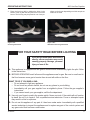
FLAME APPEARANCE
Flames from the pilot, front and rear burner should be
visually checked as soon as the heater is installed.
In addition, periodically check the flames visually during
operation.
Thermocouple
for Natural Gas
CHECK THE PILOT FLAME
The pilot flame must always be present when the
heater is in operation. It should just touch the top of the
thermocouple tip for natural gas. Refer to Figure 27 for
correct pilot flame.
If the pilot flame does not touch the thermocouple, then
the main burner cannot function reliably. Refer to Figure
28 for incorrect shape of pilot flame.
Thermocouple
for LP
FP2272
Figure 27 –
Correct Pilot Flame Appearance
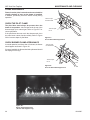
CHECK BURNER FLAME APPEARANCE
In normal operation, at full rate after 15 minutes, the flames
should appear as shown in Figure 29.
Thermocouple
for Natural Gas
If logs are installed, the flames should be yellow and should
not impinge on the logs.
Thermocouple
for LP
FP2273
Figure 28 –
Incorrect Pilot Flame Appearance
LG1181
Figure 29 –
Burner Flame Appearance
(Shown with fireglass only)
28
20305467
AVFL Vent Free Fireplace
MAINTENANCE AND CLEANING
CLEANING AND SERVICING
WARNING
Annual inspection and cleaning by your dealer or qualified service technician is recommended to prevent
malfunction and/or sooting.
Turn off heater and allow to cool before
cleaning. Disconnect electrical power
before cleaning or servicing.
ANNUAL CLEANING/INSPECTION – Refer to parts
diagram for location of items discussed below.
• Inspect and clean burner air intake holes. Remove
•
•
•
•
Remove logs, if installed, handling carefully by holding
gently at each end. Gloves are recommended to prevent
skin irritation from ceramic fibers. If skin becomes irritated,
wash gently with soap and water. Also remove glass, stones
and/or glass chunks, as applicable. Refer to manual for
correct log placement.
PERIODIC CLEANING – Refer to parts diagram for
location of items discussed below.
• Do not use cleaning fluid to clean logs or any part of
•
•
•
•
•
heater.
Brush logs and/or stones with soft bristle brush or
vacuum with brush attachment.
Clean iceberg glass with a soft wet cloth.
Vacuum loose particles and dust from the burner,
controls.
Inspect and clean burner air intake holes. Remove
lint or particles with vacuum, brush, or pipe cleaners.
Failure to keep air intake holes clean will result
in sooting and poor combustion.
The fireplace face should be dusted and wiped with
a wet soapy cloth.
•
lint or particles with vacuum, brush or pipe cleaners.
Failure to keep air intake holes clean will result
in sooting and poor combustion.
Inspect and clean all burner ports.
Inspect ODS pilot for operation and accumulation of
lint at air intake holes.
Verify flame pattern and log placement for proper
operation.
Verify smooth and responsive ignition of main burner
and rear burner.
Replace battery in remote control device.
OPERATING INFORMATION
Avoid any drafts that alter burner flame patterns. Do
not allow fans to blow directly into the fireplace. Do not
place a blower inside the burn area of the firebox. Ceiling
fans may create drafts that alter flame patterns. Sooting
and improper burning will result.
During manufacturing, fabricating and shipping, various
components of this appliance are treated with certain oils,
films, or bonding agents. These chemicals are not harmful, but may produce annoying smoke and smells as they
are burned off during the initial operation of the appliance
possibly causing headaches or eye or lung irritation. This
is a normal and temporary occurrence.
The initial break-in operation should last two to three hours
with the burner at the highest setting. Provide maximum
ventilation by opening windows or doors to allow odors to
dissipate. Any odors remaining after this initial break-in
period will be slight and will disappear with continued use.
This appliance must not be used with glass doors.
20305467
29
WARNING
AVFL Vent Free Fireplace
TROUBLESHOOTING
• Turn appliance OFF and allow to cool
NOTE: All troubleshooting items are listed in order of operation.
before servicing.
• Only a qualified service person should
service and repair the heater.
PROBLEM
Appliance produces unwanted odors.
Appliance shuts off during use.
Gas odor even when control knob is in
OFF position.
POSSIBLE CAUSE
Appliance burning vapors from paint, hair
spray, glues, etc.
SOLUTION
Ventilate room. Stop using odor causing
products while heater is running.
Gas leak.
Locate and correct all leaks.
Initial burn off.
Ventilate room and turn unit on high until
odor is gone. Odor should be gone after
six hours of continuous use.
Not enough fresh air is available for
ODS/pilot to operate.
Open window and/or door for ventilation.
Low line pressure.
Contact local gas company.
ODS/pilot is partially clogged.
Clean ODS/pilot.
Defective thermopile.
Check wire connections. Check
output should be 500 millivolts across
thermopile leads with ON/OFF switches
off.
Gas leak
Locate and correct all leaks.
Control valve defective.
Replace control valve.
Burner orifice is clogged.
Burner orifice is clogged.
Burner orifice diameter is too small.
Burner orifice diameter is too small.
Inlet gas pressure is too low.
Inlet gas pressure is too low.
Manifold gas pressure is too low.
Contact local gas company.
Burner orifice is clogged.
Clean burner or replace burner orifice.
Burner orifice is clogged or damaged.
Clean burner or replace burner orifice.
Burner is damaged.
Replace burner.
Gas regulator defective.
Replace gas regulator.
Vapor from paint or curing process of
logs.
Problem will stop after a few hours
of operation. Run the heater with the
damper open if you have one, or open a
window for the first few hours.
Burner does not light after ODS/pilot is lit.
Burner backfires during combustion.
Slight smoke or odor combustion.
Logs appear to smoke after initial
operation.
Log heater is intended to be smokeless.
Turn OFF heater and call qualified
service person.
Heater produces a whistling noise when
burner is lit.
No gas to pilot.
30
Air in gas line.
Operate burner until air is removed from
line. Have gas line checked by local gas
company.
Dirty of partially clogged burner orifices.
Clean burner or replace burner orifice.
LP regulator shut down due to inlet
pressure too high.
Verify LP tank regulator is installed and
set at 11" to 13" w.c.
Replace regulator on heater.
20305467
AVFL Vent Free Fireplace
TROUBLESHOOTING
SIGNATURE COMMAND SYSTEM
OPERATION
Install batteries and/or
plug in the AC board
FAULT
No beep in about
8 seconds
A
Using
battery?
Make sure
Command
Center and
the control
board are
connected by
a 2 feet or 15
feet cable
After the beep
Flip the master switch
(rocker switch) to the
ON position
Press the ON button on
the Command Center
No beep
or
no sound from the
valve indicating pilot
solenoid open
C
Sparking doesn’t
continue
D
Main burner doesn’t
light
20305467
B
No sparking on
the pilot
Pilot doesn’t light
ACTION
DIAGNOSIS
E
F
Check NG/LP
conversion cap
and control
board
connections
Check pilot
connections
Battery polarity wrong?
Re-install batteries
Battery voltage low?
Change batteries
AC plug is plugged to
AC mains?
Plug the AC plug to
AC mains
The 5-pin connector on
the AC board broken or
bent?
Repair or replace the
AC Board
LED on the Command
Center does not show
solid green?
Replace the AC Board
Check valve
connections
Check
grounding
Check power
supply (go
through A )
Replace the Control
Board or
Command Center
Go through
B
Sparking is happening
elsewhere (under the
pilot), re-install/replace
the pilot
The Control Board is having interference from the
surrounding metal (Ground)
Check gas supply
Go through E
Go through C
The sensor on the pilot
is not in the flame
(pilot flame too small)?
Re-install the Control
Board, move it around
or change the
Control Board
Sparking is not in the
path of gas flow, adjust
sparker position or
replace the pilot
Adjust sensor position
or replace the pilot
31
AVFL Vent Free Fireplace
REPLACEMENT PARTS
2
3
1a,b
4
6
5
8
7
FIREBOX
ITEM DESCRIPTION
1a. Bulb (20w)
1b. Bulb – Top Light (100w)
2. Bulb Socket
3. Screen Frame Assembly
4. Panel, Access, Door
5. Porcelain Panel Rear
6. Porcelain Panel Left
7. Porcelain Panel Right
8. Wire Harness
9. Junction Box Assembly (not shown)
32
QTY.
12
1
13
1
1
1
1
1
1
1
PART NO.
20301100
73D0020
73D4521
20305693K
20305434K
20305461
20305462
20305464
78D1077
26D2128K
20305467
AVFL Vent Free Fireplace
REPLACEMENT PARTS
2
1
LOGS
ITEM DESCRIPTION
1.
Log #1
2.
Log #2
QTY.
1
1
PART NO.
20305703K
20305704K
QTY.
1
1
1
1
1
2
2
2
1
2
PART NO.
20303038K
20303039K
20303040K
74D0720K
20303042K
20303043K
20303044K
74D0718K
78D0141K
74D0717K
STONES
DESCRIPTION
Large Sand Stone #1
Large White Stone #2
Large Dark Gray Stone #3
Large Brown Stone #4
Medium Sand Stone #5
Medium White Stone #6
Medium Dark Gray Stone #7
Medium Tan Stone #8
Small Tan Stone #9
Small Dark Gray Stone #10
20305467
33
AVFL Vent Free Fireplace
REPLACEMENT PARTS
3
2a,b,c,d
1
6
7
4
9
8
10
11
12
SIGNATURE COMMAND SYSTEM
ITEM
1.
2a.
2b.
2c.
2d.
3.
4.
5.
6.
7.
8.
9.
10.
11.
12.
13.
14.
15.
16.
34
DESCRIPTION
Burner Assembly
Tube, Tee to Valve
Tube, Tee to Injector
Regulator Tube
Pilot Tube
Gas Valve Assembly
Pilot Assembly
Pilot Regulator (not shown)
Control Box
Command Center
Injector
Venturi
Flexhose w/Shutoff Valve
Remote Transmitter (full function)
AC Module
Wire Valve/Control (not shown)
Wire AC Module (not shown)
Wire, CC/CB 24" w/Power Leads (not shown)
Wire, Thermocouple Module SCS (not shown)
QTY.
AVFL42NTSC
AVFL42PTSC
1
2
1
1
1
1
1
1
1
1
2
2
1
1
1
1
1
1
1
20305656K
20305454K
78D0090K
20304913K
20306010K
20303257K
14D0473
14D0469
80D0018
80D0005
20305649
45D0600
69D0030
TSFSC
80D0004
80D0010
80D0009
20301889
20301890
20305468K
20305454K
78D0090K
—
20306011K
20303258K
14D0473
—
80D0018
80D0005
62D3005
20305775K
69D0030
TSFSC
80D0004
80D0010
80D0009
20301889
20301890
20305467
AVFL Vent Free Fireplace
OPTIONAL ACCESSORIES
OPTIONAL ACCESSORIES
There are a wide range of optional accessories available
for the AVFL Vent Free Fireplace. A variety of face and trim
kits can change the appearance of the fireplace while the
rope lighting kit can add ambience and light, whether the
unit is on or off.
Choose the stylish driftwood log set, rustic stone kit,
shimmering iceberg glass or go minimalist with just a
coating of crushed glass and transform the fireplace to
suit your space.
NOTE: A face must be used to install a rope lighting kit.
Faces and Trim Kits
Wide Contemporary Textured Black Face AVFL42WFBT
Wide Contemporary Stainless Steel Face AVFL42WCSS
Black Textured Inside Fit Trim Kit
AVFL42TKI
Rope Lighting Kit
(requires wide contemporary face)
AVFL42RLK
Aged Driftwood Log
AVFL42DLS
Stone Kit
Glass Kits
Glass Kit Bronze
Glass Kit Diamond
Glass Kit Onyx
Glass Kit Sapphire
Iceberg Kits
Iceberg Kit Blue
Iceberg Kit Diamond
Iceberg Kit Sesame
SCS Wall Extension Kit
(15' wire, rough-in box, wall cover)
20305467
SKAVFL42
GKB
GKD
GKO
GKS
IKB
IKD
IKS
SCSWEK
35
AVFL Vent Free Fireplace
36
20305467
AVFL Vent Free Fireplace
20305467
37
AVFL Vent Free Fireplace
38
20305467
AVFL Vent Free Fireplace
LIMITED LIFETIME WARRANTY POLICY
LIFETIME WARRANTY
The following components are warranted for life to the original owner, subject to proof of purchase:
Firebox/Combustion Chamber/Heat Exchanger.
FIVE YEAR WARRANTY
The following components are warranted for 5 years to the original owner, subject of proof of purchase: Ceramic Fiber Logs, Catalytic Filter and Aluminized Burners.
BASIC WARRANTY
Vermont Castings Group warrants the components and materials in your gas appliance to be free from
manufacturing and material defects for a period of one year from date of installation. After installation,
if any of the components manufactured by Vermont Castings Group in the appliance are found to be
defective in materials or workmanship, Vermont Castings Group will, at its option, replace or repair
the defective components at no charge to the original owner. Vermont Castings Group will also pay
for reasonable labor costs incurred in replacing or repairing such components for a period of one
year from the date of installation. Any products presented for warranty repair must be accompanied
by a dated proof of purchase.
This Limited Warranty will be void if the appliance is not installed by a qualified installer in accordance
with the installation instructions. The Limited Lifetime Warranty will also be void if the appliance is
not operated and maintained according to the operating instructions supplied with the appliance, and
does not extend to (1) firebox/burner assembly damage by accident, neglect, misuse, abuse, alteration, negligence of others, including the installation thereof by unqualified installers, (2) the costs of
removal, reinstallation or transportation of defective parts on the appliance, or (3) incidental or consequential damage. All service work must be performed by an authorized service representative.
This warranty is expressly in lieu of other warranties, express or implied, including the warranty of
merchantability of fitness for purpose and of all other obligations or liabilities. Vermont Castings
Group does not assume for it any other obligations or liability in connection with the sale or use of
the appliance. In states that do not allow limitations on how long an implied warranty lasts, or do not
allow exclusion of indirect damages, those limitations of exclusions may not apply to you. You may
also have additional rights not covered in this Limited Warranty.
Vermont Castings Group reserves the right to investigate any and all claims against the Limited Warranty and decide upon method of settlement.
IF WARRANTY SERVICE IS NEEDED
1. Contact your supplier. Make sure you have your warranty, your sales receipt and the model/
serial number of your Vermont Castings Group product.
2. DO NOT ATTEMPT TO DO ANY SERVICE WORK YOURSELF.
20305467
39
149 Cleveland Drive • Paris, Kentucky 40361
www.vermontcastingsgroup.com