1
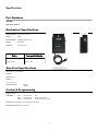
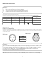
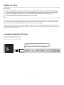
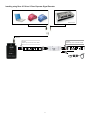
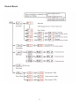
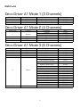
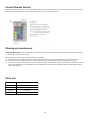
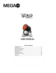
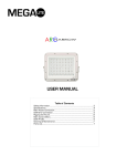
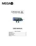
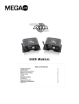
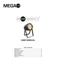
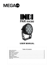
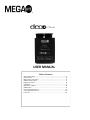
USER MANUAL
Table of Contents
Safety Information……………………………………………………………………………………………. 3
Specifications…………………………………………………………………………………………………….. 4
Main Power Connection…………………………………………………………………………………..5
DMX-512 Connection…………………………………………………………………...……………...... 5
Rigging the Fixture............................................................................................................6
Installation…………………………………………………………………………………………………………...6
Main Control Menu.......................................................................................................... 8
DMX Profile…………………………………………………………………………………………………………9
Infrared Remote Control…………………………………………………………………………….…10
Cleaning & Maintenance.............................................................................................10
Parts List............................................................................................................................10
Check that the unit has not been damaged during transport
Protection Against Fire
1.
2.
3.
4.
Maintain a minimum of 1 foot distance from any type of flame.
Do Not install the unit to close to a heat source.
Make sure cable are properly secured away from movement.
Maximum surface operating temperature 90º.
Protection Against Electrical Dangers
1.
2.
3.
4.
5.
6.
Disconnect power before servicing.
For connection to main power supply proceed to page 5.
This unit must be earthed. (electronically grounded)
Do not expose unit to rain or moisture.
The Unit must be installed in a well ventilated area.
Be sure no ventilation slots are blocked.
Protection Against Mechanical Hazards
1. Use safety chain when hanging unit
2. Unit surface may reach high temperature. Allow about 5 minutes after powering the unit before moving.
What is included
1pc Dream Drive
1pc Infrared remote control
1pc User manual
3
Specifications
Part Numbers
Fixture
5025– Deco A1 Driver
Mechanical Specifications
Fastening System:
Wall & Ceiling mount kit
Display:
Digital
Power Connection:
Cable Mounted Edison head.
Housing:
Black painted
Connection:
Cat 5 panel mount
Fixture
Packaged for Shipping
Size: 8.5” x 5.75” x 2.88”
Size: 9.25” x 7” x 3.25”
Weight: 3.63 lbs
Weight: 4.5lbs
Electrical Specifications
Power Input: 100 - 240V 50/60 Hz
Outputs: 1
Ballast: Electronic
Output: 24V
Power output: 75W
Power Consumption:
52 Watts
.72 Amps
Control & Programming
Protocol: DMX 512
3 DMX Modes:
Mode 1
Mode 2
Mode 3
3 DMX Channels
4 DMX Channels
6 DMX Channels
RGB
Dimmer / Strobe, R,G,B
R,G,B, Strobe, Macro, Dimmer
Control options: Audio-trigger, Infrared remote control (included)
Operating mode: Master/Slave, Stand alone
4
Main Power Connection
Caution!
1.
2.
3.
Do not connect fixture to a dimmer system.
This unit must be earthed. (electronically grounded)
Replace fuse only with the specified type and rating.
The occupation of the connection-cable is as follows:
The fixture is equipped with an electronic power supply that will let the unit operate 100V to 240 from 50Hz to 60Hz
Cable (USA)
Cable (EU)
Pin
110V
220V
Black
Brown
Live
L
L
White
Light Blue
Neutral
N
L
Green
Yellow/Green
Pin
N
DMX-512 Connection
The fixture is equipped with 3 pin XLR Sockets for DMX input and output. The sockets are wired in parallel. Only use a shielded
twisted pair cable designed for RS-485 and 3 pin XLR plugs and connectors in order to connect the controller with the fixture or
the fixture with another.
DMX—output
DMX—input
2
1
1. Shield
2
1
2. Signal (-)
3
3. Signal (+)
3
Caution!
At the last fixture the DMX signal needs to be terminated with a terminator. Solder a 120
Ohm resistor between the (-) and the (+) signal into a 3 pin XLR plug and plug it in to the
last fixture on the signal run. Pre-manufactured terminator plugs are available for
purchase from your Mega-Lite dealer (HOS-DMXT).
Note: After switching the unit on it will automatically detect whether DMX 512 data is received or not . If it’s receiving DMX 512
data the display screen will flash on the bottom right corner. If DMX 512 signal is not present the display will stop flashing.
5
Rigging the fixture
Caution!
1.
2.
3.
4.
The installations must be carried out by an authorized dealer or trained professional.
Unit may cause severe injures if you have doubts concerning the safety do not install.
Unit is to be 24inches away from flammable materials (decoration material)
Use high quality installation equipment to hang unit.
When rigging a unit it is very important that you follow common safety procedures. Rigging requires extensive experience including but not limited to calculating working loads, material being used and periodic safety inspections. If you lack these qualifications, do not attempt the installation yourself, instead use a professional structural rigger.
When rigging the unit always be secured with a secondary safety attachment. The installation location of the projector has got to
be built in the way that it can hold 10 times the weight for 1 hour with out any harming. Installation should be checked at least
one time a year by a skilled person.
Installation Using Deco A1 Driver
Connect Deco Ribbon to the Deco A1 Driver
Caution!
Cable may not be more than 100Ft from Deco A1 Driver
16 ’ 4 ”
6
Installing using Deco A1 Driver & Deco Repeater Signal Extender
DMX Controller
DMX Output
DMX Output
DMX Input
Caution!
Cable may not be more than 100Ft
R
B
G
7
R
Power Supply
G
Caution!
Cable may not be more than 100Ft
B
Control Board
8
DMX Profile
Deco Driver A1 Mode 1 (3 Channels)
DMX Chanel
1
2
3
Function
LED Color
LED Color
LED Color
Description
Red LED intensity
Green LED Intensity
Blue LED Intensity
Value
0-255
0-255
0-255
Deco Driver A1 Mode 2 (4 Channels)
DMX Chanel
Function
1
Dimmer
2
3
4
LED Color
LED Color
LED Color
Description
Dimmer
Strobe (slow to fast)
Dimmer Full On
Red LED intensity
Green LED Intensity
Blue LED Intensity
Value
0-152
153-242
243-255
0-255
0-255
0-255
Deco Driver A1 Mode 3 (6 Channels)
DMX Chanel
1
2
3
4
Function
LED Color
LED Color
LED Color
Strobe
5
Macro
6
Dimmer
Description
Red LED intensity
Green LED Intensity
Blue LED Intensity
Strobe (slow to fast)
No Function
Value
0-255
0-255
0-255
0-255
0-1
Color Fade (slow to fast)
Color Snap (slow to fast)
2-19
20-39
Random (slow to fast)
Audio Fade (slow to fast)
Audio Snap (slow to fast)
Audio Strobe (slow to fast)
Audio color pulse (slow to fast)
Red Pulse
Green Pulse
Blue Pulse
Yellow Pulse
Aqua Pulse
White Pulse
White LED Full
Dimmer Off to Full
40-59
60-79
80-99
100-119
120-139
140-159
160-179
180-199
200-219
220-229
230-249
250-255
0-255
9
Infrared Remote Control
Whatever mode Dream Driver is in, you can click ON button of the Infrared Controller to enter Infrared control. To exit Infrared
Control click of the OFF bottom and the Dream Driver will return to it’s previous status.
Cleaning and maintenance
Installation Maintenance: The operator has to make sure that the unit is operating safely and has the installations and electronics checked by an expert every 2 years.
The following points have to be considered during the inspection:
1) All screws used for installing the device or part of the device have to be tightly connected and must not be corroded.
2) There must not be any deformations on the housing, fixation and installation spots (ceiling, suspension, trussing).
3) The electronic power supply cables must not show any damages, material fatigue (e.g. porous cables) or sediments. Further
instructions depending on the installation spot and usage have to be adhered by a skilled installer and any safety problems
have to be removed.
Parts List
5025-IC
Infrared Remote Control
5025-MPCB
Main PCB Card
5025-DIS
Display Card
5025-PS
Power Supply
5025-CON
4 Pin Connection
10
Warranty Information
Limited Warranty
Unless otherwise stated, your product is covered by a one year parts and labor limited warranty. Dichroic filters and glass gobos are not guaranteed
against breakage or scratches to coating. It is the owner’s responsibility to furnish receipts or invoices for verification of purchase, date, and dealer
or distributor. If purchase date cannot be provided, date of manufacture will be used to determine warranty period.
Returning an Item Under Warranty for Repair
It is necessary to obtain a Return Material Authorization (RMA) number from your dealer or point of purchase BEFORE any units are returned for
repair. The manufacturer will make the final determination as to whether or not the unit is covered by warranty. Lamps are covered by the lamp
manufacturer’s warranty.
Any Product unit or parts returned to MEGA Systems Inc. must be packaged in a suitable manner to ensure the protection of such Product unit or
parts, and such package shall be clearly and prominently marked to indicate that the package contains returned Product units or parts and with an
RMA number. Accompany all returned Product units or parts with a written explanation of the alleged problem or malfunction. Ship returned Product units or parts to: 5711 Kenwick St. San Antonio TX 78254 USA.
Note: Freight Damage Claims are invalid for fixtures shipped in non-factory boxes and packing materials.
Freight
All shipping will be paid by the purchaser. Items under warranty shall have return shipping paid by the manufacturer only in the Continental United
States. Under no circumstances will freight collect shipments be accepted. Prepaid shipping does not include rush expediting such as air freight. Air
freight can be sent customer collect in the Continental United States.
REPAIR OR REPLACEMENT AS PROVIDED FOR UNDER THIS WARRANTY IS THE EXCLUSIVE REMEDY OF THE CONSUMER.
MEGA SYSTEMS INC. MAKES NO WARRANTIES, EXPRESS OR IMPLIED, WITH RESPECT TO ANY PRODUCT, AND MEGA SYSTEMS SPECIFICALLY DISCLAIMS ANY WARRANTY OF MERCHANTABILITY OR FITNESS FOR A PARTICULAR PURPOSE. MEGA
SYSTEMS SHALL NOT BE LIABLE FOR ANY INDIRECT, INCIDENTAL OR CONSEQUENTIAL DAMAGE, INCLUDING LOST PROFITS, SUSTAINED OR INCURRED IN CONNECTION WITH ANY PRODUCT OR CAUSED BY PRODUCT DEFECTS OR THE PARTIAL
OR TOTAL FAILURE OF ANY PRODUCT REGARDLESS OF THE FORM OF ACTION, WHETHER IN CONTRACT, TORT (INCLUDING
NEGLIGENCE), STRICT LIABILITY OR OTHERWISE, AND WHETHER OR NOT SUCH DAMAGE WAS FORESEEN OR UNFORESEEN.
Warranty is void if the product is misused, damaged, modified in any way, or for unauthorized repairs or parts. This warranty gives you specific
legal rights, and you may also have other rights which vary from state to state.
Mega-Lite
5718 Kenwick St
San Antonio, TX 78238
Ph 210-684-2600 Fax 210-855-6279
www.mega-lite.com / [email protected]