1
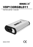
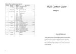
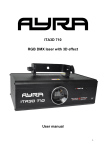
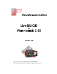
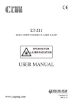
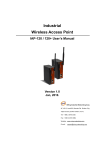
Shogun 3D+RGB
ORDERCODE 30974
ATTENTION
1. Must operate according to the user manual. Don't separate the light personally.
Call the technician when the machine breaks down.
2. Please do not see the laser beam directly to avoid any damage.
3. Before connect or disconnect the power, please adjust the luminance of the
laser diode to the least to avoid any damage to the laser diode.
4 . This unit should be keep dry, do not use in the rain or dank and dusty
environment. It can be use in the outdoor with the water-proof cover protector.
5. Set the light immobility and try to avoid strong shake or hit.
6. Prevent dust into the equipment to avoid problems.
7. Please keep that there's no other equipment or decorating materials obstructed
the exhaust fan and the vent-pipe when the equipment was working.
8. Before connect power, check the plug is immobility or not, power line should
be connect well.
9. Please do not open or close the equipment frequently that's to avoid any affect
to the life span of the laser diode, and try the best to avoid the long time
working.
10. Due to the characteristic of the laser diode, after three hours working, it
should be close at least 25 minutes until the laser diode cooling then work
again.
11. Don't touch the light or draw the power line when your hand was wet. And do
not pull the electronic power line.
12. Maintain the distance at least 10M above from the equipment to the object.
13. This equipment does not have any parts can repair for the users, please do not
open the equipment.
14. When the laser diode became dim or damaged please contact the dealer timely.
15. To use the original package when transport again and to avoid shake.
16. When use this equipment, you must turn on the lamp at first and then start the
computer .If you open software before turn on the lamp, please restart the
software.
Warning
1、Don't look the light directly to prevent make some destroy with eyes..
2、Keep the space between light equipments and the lighted things more than 10 M.
OPEN THE BOX FOR CHECKING
In order to use this product safety and reasonable for the users, please read over
this manual carefully before use and the operation must strictly according to this
manual to avoid any damage to the product and personal safety.
Once after received this products please take and put carefully. And check
carefully that whether the product was damaged or not during the transportation and
please check the following things were enclosed:
Laser light 1PCS
Graphics USB card 1PCS
9 pin signal line 1PCS
USB connection cable 1pcs
3 pin signal line 1pcs
User manual 1pcs
Power cable 1PCS
Install CD-ROM 1PCS
INSTALLATION
1. Please check the voltage whether is the same with the one showed on the
equipment or not.
2. It must ask for the technical person and set the light safety when installation. And
let the light beam at the suitable angle.
3. When install this equipment please make sure there's no flammable surfaces
(decorated things, etc) within at least 1.5M and maintain minimum distance of
0.5M from the equipment to the walls.
4. Please make sure that there's no other equipment or decorating materials
obstructed the exhaust fan and the vent-pipe.
5. Products should be install immobility.
6. In case of safety, it's very important that to connect the earth with line.
CONTROL BOARD INSTRUCTION
RGB LASER
Po we r 1 2 0W
Cla ss 1
Re d
L as e r Class 3 B 6 35 n m >1 5 0m W
G re e n L a s er Class 3 B 5 3 2n m >6 0 mW
Blu e L a s er Class 3 B 4 7 3n m >1 0 0m W
POWER INPUT: Input power, with inner fuse.
PC SIGNAL IN/OUT: USB connection port signal input/output
DMX IN/OUT: DMX 512 signal input/output
POWER ON/OFF: power on/off
Donwload2 : Download method 2 used
MIC: Receive Music.
MIN-MAX: Music sensitivity potentiometer
th
th
ADDRESS: the 10 code is switch code. When the 10 code is OFF, 1~9 are
function codes. When function code is 0, the working mode is Music Active
(Master mode); when function code is 1, the working mode is Automatic (Master
mode); when function code is 2 or more, the working mode is Slave mode. When
th
the 10 code is ON,1~9 will be DMX address codes. The address code of first
light usually by 1, the second light is 14 and so on.
ILDA DB 25 F Connector : signal input connection port of the laser perform
software that in accordance with the ILDA standard.
NOTE:
1. When PC SIGNAL IN and ILDA DB 25F connector ’s connection port are free,
the lamp will drive by the inside program, temporality it can control by music or
DMX 512 signal.
2. When PC SIGNAL IN connects with USB interfacial card, the lamp will be
control by software which was installed in the computer.
3. After connect the ILDA DB 25F, The lamp will change to ILDA connected port
drive mode ,this connection port can receive all the signal of laser perform
software that accord with the ILDA standa rd, such as LD-2000 of Pangolin
Company.
4.When the PC SIGNAL IN and the ILDA DB 25F Connector were connected, then
the system will at an abnormal statement, lamp still control by inside program ,
but not respond to the exterior input signal.
music mode/auto mode/slave mode setting:
FUNCTION
This bit disable DMX mode and
enable music/auto slave mode
MUSIC MODE
AUTO MODE
SLAVE MODE
DMX address code setting:
in the binary, each digit have “0”or “1”just correspond to “OFF”or “ON ”switch situation.
Example for DMX address code:
DECIMAL
LSB
MSB
This bit enable DMX mode
DMX512 OPERATE
The product has 13 operate channels(international standard DMX512 signal),The details
as follow:
CHANNEL
1
Control Mode
2
Color
3 Pattern
4 Speed
5
horizontal &
vertical roll
6
Rotation &
Point-Draw
DMX512
VALUE
0-63
64~127
128~191
192~255
0~22
23~45
46~68
69~91
92~114
115~137
138~160
161~183
184~206
207~229
230~252
253~255
0~255
0~255
0-63
64~127
128~191
192~255
0-63
64~127
128~191
192~255
FUNCTION
Music Active, 5-13channels out of effect
Stand Alone, 5-13 channels out of effect
Manual (Music Active)
Manual (Automatic)
Close
White
Red
Yellow
Green
Cyan
Blue
Purple
Full multi color
Stochastic single color
Stochastic multiple color
Fluent
64 patterns(0~255)/4=(0~63)
12 grade speed(0~255)/23=(0~11)
No rolling
Horizontal roll
Vertical roll
Horizontal & vertical roll
No Rotation & No Point-Draw
Rotation
Point-Draw(Only Point)
Rotaion & Point-Draw
0-63
64~127
128~191
192~255
0~63
64~127
128~191
No move
Horizontal move
Vertical move
Horizontal & vertical move
9
Small To Large &
Large To Small
192~255
0~85
86~169
170~255
Horizontal & vertical stretch
No Zoom
10
Slow-draw
speed
0~255
255 grade speed
11
Scan Speed
0~255
255 grade speed (fast to slow)
12
Change Color Speed
0~255
12 grade speed(0~255)/23=(0~11)
7
Horizontal &
vertical move
8
Horizontal &
vertical stretch
13
Size
0
No stretch
Horizontal stretch
Vertical stretch
Zoom from one point to large
Zoom from large to one point
(fast to slow)
Original size
1~255
42 grade size(1~255)/6=(0~42)
0~19 reduce 20 original size 21~42blow up
SPECIFICATION
Voltage: AC 220V~240V, 50/60Hz
Signal input power: -15~+15V
X/Y axes beam scanning optical angle: 0~+/-30°
Input signal bandwidth: 0~1000Hz
Condition temperature: -10°C~35°C
Total power: 120W
Laser light power: Red
Laser Class 3B 635nm >150mW
Green Laser Class 3B 532nm >60mW
Blue Laser Class 3B 473nm >100mW
Frequency of MCU :24MHz
Size of flash rom for download :32K Byte
Net weight: 27 kg
Dimension: 62 x 30 x 19.5 cm
MAINTAIN
Maintenance should be performed every 15-day period, by using a sponge which is
dipped with alcohol, rather than wet cloth or other chemical liquid, to clean the mirror.
Warning: Power must be disconnected before maintenance or repair. Do not look at the
light source directly.
ATTENTION: DISCONNECT INPUT POWER BEFORE MAINTAIN.
DON'T LOOK STRAIGHTLY AT THE LIGHT SOURCES.
NOTE: Don't seperate laser machine from laser power and repaire them by yourself
otherwise no good repair service will be supplied.
B
Lin
1 2 3 4 5 6 7 8 9
1 2 3 4 5
6
7 8
9
S2 & S3
TTL-SWITCH BOARD
Description for TTL-switch board:
This board have three input source, they are
Internal Programboard (X1,Y1,R1,G1,B1) and
ILDA DB25F (X2,Y2,R2,G2,B2) and
USB graphics interface card (X3,Y3,R3,G3,B3).
The signal S2 & S3 determine who can become master.
If S2=0 and S3=1 then ILDA DB25F become master.
If S2=1 and S3=0 then USB g.i.c become master.
If S2=1 and S3=1 then Internal P.B. become master.
If S2=0 and S3=0 then Internal P.B. become master.
Appendix:
ILDA DB 25F PINOUTS DB 25 definens
1
X+
-5 to +5V
2
Y+
-5 to +5V
3
Intensity/Blanking+
0V to +2.5V
4
Interlock A
Connected to pin 17 inside the Qm2000
5
Red+
0V to +2.5V
6
Green+
0V to +2.5V
7
Blue+
0V to +2.5V
8
Deep blue+
0V to +2.5V
9
Yellow+
0V to +2.5V
10
Cyan+
0V to +2.5V
11
Z+
Depth Z(not intensity), -5 to +5V
12
Not connected
13
Shutter
0V to +5V
14
X-
-5V to +5V
15
Y-
-5V to +5V
16
Intensity/Blanking-
-2.5V to 0V
17
Interlock B
Connected to pin 4 inside the Qm2000
18
Red-
-2.5V to 0V
19
Green-
-2.5V to 0V
20
Blue-
-2.5V to 0V
21
Deep blue-
-2.5V to 0V
22
Yellow-
-2.5V to 0V
23
Cyan-
-2.5V to 0V
24
Z-
-5V to +5V
25
Ground
Cable shield
Version 1.0
2005 Showtec.