1
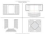
manual GB
rev.2 nov-07
RESL
Hardware system for
side sliding sectional
garage doors
INSTALLATION / MAINTENANCE / USAGE
© All rights reserved. FlexiForce® 2007
RESL manual GB 07
Rev10
www.flexiforce.com
manual GB
rev.2 nov-07
ATTENTION! GENERAL WARNING!
To install, use and maintain this door safely, a number of precautions must be taken. For
the safety of all concerned, pay heed to the warnings and instructions given below! If in
doubt, contact your supplier.
9
9
9
9
9
9
9
This manual has been written for use by experienced fitters and as such is not
suitable for d.i.y. purposes or for use by trainee fitters.
This manual describes the installation of the hardware set components, door
sections (panels) and refers to installation manuals of the electrical operator. Be
sure to supplement this manual if needed with instructions for any additional
components not described in this manual.
Before starting, read this manual carefully!
Certain components may be sharp or have jagged edges. As such you are advised to
wear safety gloves.
All the components which have been supplied are designed for use with this specific
overhead door. Replacement or adding additional components may have an adverse
effect on the safety of, and the guarantee on, the door. Also the CE-approval which
has been granted to this door will be cancelled when components are changed or
installation is not done according to this manual! Installer is responsible for this.
Ensure that there is sufficient light during installation. Remove obstacles and dirt.
Make sure that there is no one else present other than the fitters. Other people
(children!) may get in the way or endanger themselves during the installation.
SPECIAL SAFETY WARNINGS OR REMARKS IN THIS MANUAL ARE INDICATED WITH
THIS SYMBOL:
READ THESE WARNINGS CAREFULLY.
GUARANTEE, CONDITIONS AND TERMS
The general terms and conditions of delivery and payment issued by the Metaalunie and designated as
METAALUNIE CONDITIONS are fully applicable to all our quotations, contracts and their
implementation. We expressly reject all other terms and conditions. On request we will send you a copy
of these terms and conditions free of charge. A copy may also be downloaded from our website
www.flexiforce.com.
FlexiForce strives to deliver 100 % in conformance with the order. In practice, in spite of all our controls,
this is not always possible. However we will rectify any errors as quickly as possible, in order to minimise
the inconvenience caused to you or the user. As such, it is important that you inform us as soon as possible
about any problem with the delivery (include the order number and week of production) and give us the
opportunity to offer a suitable solution.
FlexiForce will only reimburse third party costs if we have given explicit permission for this in advance. The
reimbursement is based on normal rates and travelling expenses over distances of 1 hour away at most.
For large-scale projects we strongly advise you to first install 1 door completely before installing the other
doors. In this way, any errors can be detected early on and rectified comparatively cheaply.
This manual does not confer any rights. Technical modifications may be made without written notice.
FlexiForce has endeavoured to design and put together this hardware set in conformance with the
applicable CE-norms. However, we recommend to check our configuration against any local national
specification.
RESL manual GB 07
www.flexiforce.com
manual GB
rev.2 nov-07
FlexiForce has applied the mandated INITIAL TYPE TESTING for doors described in this manual,
at the SP-Institute in Sweden (as Notified Body Nr. 0402). The INITIAL TYPE TESTING REPORT
that has been rewarded, can be transferred to the door producing company. This is needed to
complete your CE files according to product standard EN13241-1. Contact FlexiForce for
acquiring this report.
APPLICATION RANGE
FlexiForce has developed a completely new hardware system for side sliding, residential (garage)
sectional doors. Designed for all built-in situations depending on the available space. The system
includes the following features:
x Suitable for single and double garages, Wmax = 5 m, Hmax = 2,5m.
x Max door weight is 170 kg
x CE approved when selecting the proper FlexiForce components.
In this handbook we restrict our instructions for the proper assembly of the complete door. For
installation of not mentioned products or parts, including any components added by the supplier, as
well as for a user handbook, we refer you to the supplier of the complete overhead door who is also
responsible for the correct CE marking of the door. These instructions have been prepared for use by
experienced professional fitters and are therefore not suitable for the “DIY” fitter or the apprentice
fitter.
This door can only be installed according to the CE-certificate if all parts are according to the parts lists
of the SP-certificate. See www.flexiforce.com.
We wish you every success with the installation of this hardware set. If anything is unclear or
should you have queries, you should of course contact Flexi-Force B.V. or your supplier.
This set has to be completed with the assembled door sections. Panels brands and types
according to the list of approved panels.
Attention! In this set, the fixing material required to install the track set to the building is not
included. It is the responsibility of the qualified door installer to make sure that the building
(stone, concrete, wood, etc.) is strong enough at the points of fixation to ensure a reliable
construction. The door installer has to select proper fixing materials.
TOOLS REQUIRED FOR CORRECT AND RAPID ASSEMBLY
(Battery) drill with
Bit 4.0 mm
Bit 6,5 mm
Plug 10 mm
Plug 13 mm
4 mm
8mm (in)
10 mm
13 mm
15 mm
17 mm
with ¼” square
Hexagonal key
Socket screw spanner
Ring /open ended spanner
Ring /open ended spanner
Ring /open ended spanner
Ring /open ended spanner
Socket wrench
Wrench
Gluing clamp
Cord
Water level (hose)
2 blocks of ca. 20 en 40mm in height
Measuring equipment
RESL manual GB 07
www.flexiforce.com
,QVWDOODWLRQVW\SHV THFKQLFDO'LPHQVLRQV
· ,IWKHVLGHDUHDLQWKHFXUYHVLGH/&KDYHDGLPHQVLRQODUJHUWKDQ 700mm,WKH motor
FDQEHLQVWDOOHGLQWKHOLQWHO.
·,I ERWKVLGHDUHDVKDYHGLPHQVLRQVLQIHULRUWR00mm,WKH motorPXVWEHLQVWDOOHGLQWKHVLGH
ZDOORQWKHRSHQQLQJVLGH.
InstalOaWLRQ 1
,QVWDOODWLRQV7\SH: 1 2
LC = 150mm mLnimXP
700mm máximXP
LF = 70mm
DM = V3 + 500mm
DP = V3 + 300mm
P = 110 mm/130mm mLnimXPZ/ motor
Legenda:
LC - LateralFXUYH VLGHDUHD
LF - Lateral/RFN
VP - 'D\OLJKW
DM –:DOOPHVXUHZLWKPRWRU
DP –:DOOPHVXUHZ/PDQXDOGRRU
P -/LQWHO
InstalOaWLRQ 2
InstalOaWLRQ 3
InstalOaWLRQW\SH: 3 4
LC = 700mm mLnimXP
LF = 70mm
DP = VP + 300mm
P = 110/130mm mLnimXPZ/ motor
InstalOaWLRQ 4
InstalOaWLRQ 5
InstalODWLRQW\SH: 5 6
LC = 600mm
LF = 500mm
DP = VP + 300mm
P = 110/130mm mLnimXPZLWK motor
InstalOaWLRQ 6
manual GB
rev.2 nov-07
CHECKING DIMENSIONAL DETAILS
Before assembling the system the details below should be checked on the basis of this figure.
A = Days Opening Width = DLW
B = Days Opening Height = DLH
C = Side area
D = Top area
E = Side wall free space
= DLH
DLW max = A max = 5.000mm
DLH max = B max = 2.500mm
C min = 150mm (curve side), 70mm
D min = 100mm (manual operated)
115mm (power operated Marantec)
142mm (power operated Liftmaster)
E min = A
= DLW
PARTS LISTS RESL DOOR
Qty for
door
2,5x2,5m
Article code
Explanation function
5060L3240
5060L5220
Suspension angle,
horizontal, lintel. Together
with the RL310 and RL320,
this is the suspension of the
2V running track
1
2RL925-400
Upper curve RESL, 2V-Jcorner, made out of
standard 2V track, bended
differently on special new
tooling in FF HU
1
Qty for
door
5 x 2,5m
Upper track + suspension
RESL manual GB 07
1
1
www.flexiforce.com
manual GB
Qty for door Qty for door
2,5x2,5m
5 x 2,5m
rev.2 nov-07
2V
Standard 2V track for upper
guidance at the lintel, length
is Door Width - 370mm
1
1x
4630mm
2V
Standard 2V track for upper
guidance at the wall side,
length is Door Width
+130mm
1
1x
5130mm
RL300
Angle bracket for track
suspension on the wall. In
combinaiton with RL310 and
RL320
5
10
RL310
Top bracket, together with
RL320 this carries the 2V
track
9
20
RL320
Rail plate, in combination
with the RL310, this carries
the 2V track
9
20
RESL manual GB 07
www.flexiforce.com
manual GB
rev.2 nov-07
Qty for door Qty for door
2,5x2,5m
5 x 2,5m
2
2
RL330
2V-connection bracket, at
the point where the upper
curve and 2V track connect
1088B
Socket capscrew, forms the
"shaft" which connects the
double roller RL592 with the
hinge on the panel.
M10x140mm.
5
10
2050
Washer. Steel washer that is
placed between the bolt
1068MN and the collar of the
RL592
5
10
2052
Washer. Nylon washer that
is placed between the bolt
1068MN and the collar of the
RL592
5
10
RL592
Roller system. Double roller
combination that runs in the
2V track. Integrated finger
protection.
5
+ 1 for
E-power
10
+ 1 for
E-power
Upper roller system
DIN912
DIN125A
DIN433
Seals and brushes
RESL manual GB 07
www.flexiforce.com
manual GB
Qty for door Qty for door
2,5x2,5m
5 x 2,5m
rev.2 nov-07
1030L-S6090
Aluminium bottom profile.
Used as "end cap" at the
bottom side of the door. NB!
For fingersafe sections, this
profile has to be cutted into
section height, following
more or less the shape of
the panel. At this position is
also holds the 1038INS2550
and the sealing brush
1087B.
Also used at both sides of
the doorleaf. In 1st panel
with seal 1037. In last panel
without seal.
2
5
(2pcs
2990
1pcs
5100)
1038INS2550
1038INS3050
Alu profile for holding the
brush 1087B. It fits into the
1030L-S profile.
1
2
3 mtr
5 mtr
1
1 pcs
5000
or
2pcs 3015
1087B1
91VR3015
91VR5000
Brush. Forms the seal
between panel and steel
threshold RLT3000.
Alu profile that is used in
combination with the new
seal 1088S at the sides and
lintel part of the door. At the
outside of the door this
gives a proper appearance
(black line around the door).
RESL manual GB 07
www.flexiforce.com
manual GB
Qty for door Qty for door
2,5x2,5m
5 x 2,5m
rev.2 nov-07
1088S-3060
3
5
2,5 mtr
2,5 mtr
Vertical angle. On the
closing side of the door,
fitted on the wall, together
with 2100-15. So the 1037
closed to this profile. Is
standard 9VR only more
holes.
1
1 pcs
415RL
End roller bracket. Holds the
447 slide with RL580 roller.
Is fitted on the first panel of
the door (so in the corner)
1
1
447RL
Slide 11mm. Roller carrier
for RL580. Used on the first
panel in combination with
415RL, on the last panel
used alone (directly on the
panel)
3
3
1037
9VRL2525
9VRL3025
Sealing, that fits on the
91VR alu profile.
Seal. Standard available FF
seal. Fitted at the side of the
first panel, into the 1030LS6090. It seals of the
"locking" side of the door,
against the 9VRL angle that
is fitted on the wall.
Hinges and brackets on the panels
RESL manual GB 07
www.flexiforce.com
manual GB
rev.2 nov-07
RL580
Bottom roller. Guides the
door through the steel
threshold RLT3000.
Qty for door Qty for door
2,5x2,5m
5 x 2,5m
6
11
423FZ etc.
Hinge. Standard FF hinge
range 424FZ, 423FZ can be
used. At top and bottom.
8
18
40ES500L/R etc.
Endcap. Standard FF end
caps to cover the upper
parts of the sections.
4
9
423HZ etc.
Intermediate hinge.
Standard FF hinge
depending on panel choice.
4
9
RLB-L/R
Bottom corner. "Low side
room" corner. Connects to
steel threshold and to 2x
RL15U3000 bottom tracks.
1
Left
Or
Right
1
Left
Or
Right
Bottom track and curves
RESL manual GB 07
www.flexiforce.com
manual GB
rev.2 nov-07
RLT3000
RL15U3000
Threshold, steel. Days
opening width - 250mm.
With holes for mounting to
the floor. Guides the panel
through the days opening.
Qty for door Qty for door
2,5x2,5m
5 x 2,5m
1
2
U-profile. To be assembled 2
next to each other,
connected with 850RL
plates. Length is Days
opening width. Guides door
sections along the side wall.
2
4
850RL
Rail fixing strip for
assembling 2 x RL15U3000
tracks.
4
8
650L
Lock extension. If you take a
standard 650BL-etc. lock,
you can add this 650L part
with latch and strike. One
piece is mounted on the
9VRL angle. The other piece
on the panel.
option
option
901
Anti-lift bracket. If the door
is mounted, 3 of these
brackets ensure that you
cannot lift the door out of
the bottom track. So, burglar
protection. E-operation
3x901 is needed. Manual
operation 2x901 and then on
the side of the panel 1 x
902H/902WB
2 or 3
2 or 3
Locking / anti-burglar products
RESL manual GB 07
www.flexiforce.com
manual GB
rev.2 nov-07
902H
902WB
Anti-lift bracket. If you
mount this bracket on the
door panel (corner panel),
and you fix the 902WB to the
wall, when closing the door
these "click in" and prevent
that the door can be lifted
out of the threshold.
Anti-lift bracket. If you
mount this bracket to the
wall and fix the 901H on the
door panel (corner panel),
when closing the door these
"click in" and prevent that
the door can be lifted out of
the threshold.
Qty for door Qty for door
2,5x2,5m
5 x 2,5m
1
1
Only
manual
operation
Only
manual
operation
1
1
Only
manual
operation
Only
manual
operation
E-operation parts
RL210
E-bracket
1
1
RL220
Drive unit bracket
1
1
RL230
Draw arm
1
1
RESL manual GB 07
www.flexiforce.com
manual GB
rev.2 nov-07
Qty for door Qty for door
2,5x2,5m
5 x 2,5m
1
1
557-90Z
Roller (later replaced by
RL555)
557BUS8
Bush
2
2
1057B16
Hex.bolt M8x16
1
1
1057B60
Hex.bolt M8x60
1
1
1059B50
Hex.bolt M10x50
1
1
1068MN
Nyloc moer M8
1
1
Fixation material and fasteners
ISO4017
ISO4017
ISO4014
DIN985
RESL manual GB 07
www.flexiforce.com
manual GB
rev.2 nov-07
Qty for door Qty for door
2,5x2,5m
5 x 2,5m
9
20
1072B
Mushroom bolt
1006B
Pressbolt M6
9
9
1055BV
Screw
60
90
Flange nut M10
1
1
1062BF
Flat mushroom M6x16
2
2
1062M
Flange nut M6
11
11
DIN603
1058F
RESL manual GB 07
www.flexiforce.com
manual GB
rev.2 nov-07
Qty for door Qty for door
2,5x2,5m
5 x 2,5m
13
24
1068M
Flange nut M8
2100-15
Buffer
1
1
Nyloc moer M10
5
10
2510BMOE
CALCULATION LENGTHS OF PROFILES
Product code
1038INS2550
1087B
1088S
5060L
91VR
9VRL
RL15U3000
RLT3000
1030L-S
1037
2V front
2V side
Description
Brush alu profile
Brush
Sealing
L profile suspension
Alu profile
Angle
U-profile
Threshold
Bottom profile
Side seal
Track lintel
Track wall
Formula for length
DLW(A)+40mm
DLW(A)+40mm
DLH(B)+25mm (2x) and DLW(A) (1x)
DLW(A)+180mm
DLH(B)+25mm (2x) and DLW(A) (1x)
DLH(B)+25mm (2x) and DLW(A) (1x)
DLW(A) (2x)
DLW(A)-250mm
DLH(B)-10mm (2x) and DLW(A)+100mm (1x)
DLH(B)-10mm
DLW(A)-370mm
DLW(A)+130mm
RESL manual GB 07
www.flexiforce.com
manual GB
rev.2 nov-07
MAX TORQUE FIXATION MATERIALS
RESL manual GB 07
www.flexiforce.com
manual GB
rev.2 nov-07
INSTALLATION 5060L ON LINTEL
5060L-
RESL manual GB 07
www.flexiforce.com
manual GB
rev.2 nov-07
RL320
RL310
1072B
RESL manual GB 07
www.flexiforce.com
manual GB
rev.2 nov-07
INSTALLATION SUSPENSION SIDE WALL
RL300
RL320
RL310
RESL manual GB 07
www.flexiforce.com
manual GB
rev.2 nov-07
INSTALLATION OF UPPER TRACK IN SUSPENSION
2RL925-400
RL330
2V…
RESL manual GB 07
www.flexiforce.com
DETACHABLE: Remove the leaf of the book
Customer Declaration
Company stamp / Installer:
Standard EN 13241-1
Customer name:
O.F. (See CE Marking plate):
The Customer received/verified that:
Yes
The door is complete and instalalled in proper conditions, without visible defects.
The door works as expected, and without risks for the users
The client received the Instructions and Documents:
Use of security anss emergency devices
CE Declaration
Copy of the test for limitation of forces (if necessary)
Instruções de Operation, Use and Maintenance
Some elements of the door need maintenance/control at least
two times by year (according to the standard EN 13241-1).
The Installer proposed to the client to sign a Maintenance Contract
The customer has accepted the Contract of Maintenance to the Door
Observations:
By signing this document, the customer declares that:
Received maintenance instructions for the door, and that read these instructions
Allow this document is available to all people Authorized
Ensures that will use the door in a correct way, and that will keep it in good condition, as described in the instructions.
SECTIONAL DOORS
/
Installation adress:(if diferent from customer)
Other Informations
Customer adress:
Date:
Name and Installer siganture:
/
Name and Customer signature:
No
BOOK FOR REGISTRY OF MAINTENANCE
(Data to be completed by the technician before handing over to client)
Technical Data of Door and Installation
Company Name:
Adress:
Installation Date:
/
/
Contact:
Plate Serial Number of Door (O.F.) :
Customer:
Work Location:
/
/
Contact:
Manufacturer: FLEXIDOOR - Portões Seccionados e Automatismos,S.A.
Adress : Rua da Majoeira | Nº400 | Apartado 542
2415 - 184 | Regueira de Pontes
Leiria | Portugal
Contact : Tel.: +351 244 850 470 Fax: +351 244 850 471
Door Model:
Automatic Door
Sectional Residential
High Speed:Roll-up
Sectional Industrial
High Speed:Folding
with Pass Door
Sectional Sliding Door
List of Safety Devices Used
(Make the description of the security devices used)
Engine:
Electric Board:
Photocells:
Comand Device:
Other:
Other:
Model,type
Model,type
Model,type
Model,type
Model,type
Description of Intervention
(Signal X in the intervention made, and describe the work of the intervention, tuning parameters of the engine as well as possible errors in use)
Assembly
Date:
/
/
Installer name:
Test
Maintenance
Repair
Modification
Customer signature:
Installer signature:
Description of Intervention
(Signal X in the intervention made, and describe the work of the intervention, tuning parameters of the engine as well as possible errors in use)
Inspection
Date:
/
/
Installer name:
Test
Maintenance
Repair
Customer signature:
SECTIONAL DOORS
Installer signature:
Modification
Description of Intervention
(Signal X in the intervention made, and describe the work of the intervention, tuning parameters of the engine as well as possible errors in use)
Inspection
Date:
/
/
Installer name:
Test
Maintenance
Repair
Modification
Customer signature:
Installer signature:
Description of Intervention
(Signal X in the intervention made, and describe the work of the intervention, tuning parameters of the engine as well as possible errors in use)
Inspection
Date:
/
/
Installer name:
Test
Maintenance
Repair
Modification
Customer signature:
Installer signature:
Description of Intervention
(Signal X in the intervention made, and describe the work of the intervention, tuning parameters of the engine as well as possible errors in use)
Inspection
Date:
/
/
Installer name:
Test
Maintenance
Repair
Modification
Customer signature:
Installer signature:
Description of Intervention
(Signal X in the intervention made, and describe the work of the intervention, tuning parameters of the engine as well as possible errors in use)
Inspection
Date:
/
/
Installer name:
Test
Maintenance
Repair
Customer signature:
SECTIONAL DOORS
Installer signature:
Modification
manual GB
rev.2 nov-07
+-35mm
INSTALLATION VERTICAL ANGLE 9VRL
RESL manual GB 07
www.flexiforce.com
,167$//$7,21%27720*8,'(75$&.
INSTALL THE CURVE:
-If the side area (C) in the
curve side is inferior to 440mm
use the 290mm as measure
-If the side area (C) is superior
to 440mm use the 45mm as
measure to place the curve
manual GB
rev.2 nov-07
RL15U3000
850RL
This track its not applied if the side area
"C" is bigger than 500mm
RESL manual GB 07
www.flexiforce.com
manual GB
rev.2 nov-07
PANEL ASSEMBLY (CUTTING PANELS TO SIZE)
RESL manual GB 07
www.flexiforce.com
manual GB
rev.2 nov-07
PANEL ASSEMBLY: CUTTING TO SIZE OF 1030L-S6090
1st panel
Intermediate panels
Last panel
RESL manual GB 07
www.flexiforce.com
manual GB
rev.2 nov-07
PANEL ASSEMBLY (STARTING WITH 1 st PANEL)
447RL
(top view ↑)
420FZ etc.
40FM500L/R etc.
RESL manual GB 07
www.flexiforce.com
manual GB
rev.2 nov-07
(top of panel ↓)
(bottom of panel ↓)
1038INS2550
1087B
(bottom view ↑)
1030L-S6090
1037
RL580
RESL manual GB 07
www.flexiforce.com
manual GB
rev.2 nov-07
2510BMOE
2050
2052
RL592
1088B
RESL manual GB 07
www.flexiforce.com
manual GB
rev.2 nov-07
(last panel ↓)
447RL
415RL
RL580
INSTALLING THE PANELS (SECTIONS) IN THE TRACK SYSTEM
RESL manual GB 07
www.flexiforce.com
manual GB
rev.2 nov-07
RESL manual GB 07
www.flexiforce.com
manual GB
rev.2 nov-07
FIXATION LATERAL HINGES AND INSTALLATION INTERMEDIATE HINGES
423HZ etc.
ADJUSTING PANEL POSITIONING
(position last roller in
the “upper” curve)
C
The roller is applied in this
track if the "C" mesure is
bigger than 500mm
( ← position top of panel to 901 lift protection)
RESL manual GB 07
www.flexiforce.com
manual GB
rev.2 nov-07
INSTALLING 902H, 902WB ANTI-LIFT BRACKETS
RESL manual GB 07
www.flexiforce.com
manual GB
rev.2 nov-07
INSTALLATION SIDE AND TOP SEALS
(top view)
INSTALLING END STOP IN SIDE TRACK
2100-15
RESL manual GB 07
www.flexiforce.com
manual GB
rev.2 nov-07
E-OPERATION INSTALLATION
RL220
(days opening →)
RESL manual GB 07
www.flexiforce.com
manual GB
rev.2 nov-07
(operator bracket system)
1057B60
557BUS8
RL230
RL210
RESL manual GB 07
www.flexiforce.com
manual GB
rev.2 nov-07
1059B50
1057B16
RL592
1068MN
RESL manual GB 07
www.flexiforce.com
manual GB
rev.2 nov-07
(top view E-system)
ATTENTION WITH E-OPERATION
When you have selected an electrical operator drive (RES-E-500 or other),
then this should be assembled in conformity with the handbook supplied
with this operator and above displayed instructions. You should clearly
follow the instructions for electrical operation in this handbook.
In order to maintain the closing peak force of the door within the CEstandards the attachment point (97014) of the drawbar should be fixed at
the proper position. Ask your supplier for the correct position.!
NB! The person installing the door must check thoroughly if the
combination between this door and the selected operator is safe to use
(ITTR-approval report). Keep in mind the max. peak force that is allowed
when closing the door. People could get hurt if the adjustment of the
operator software, or the installation of the operator or the selected
operator on this door, are not checked correctly!!
RESL manual GB 07
www.flexiforce.com
manual GB
rev.2 nov-07
FINISHING THE DOOR
Install any additional accessories that you have ordered separately such as:
Handgrip, lock, etc. See separate instructions in product packaging.
NB!
A lock may not be fitted to an electrically driven door.
NB! A manually operated door should always be equipped with a hand grip,
installed at a safe location on the door.
x
Oil all hinges and all bearing rollers with one drop of oil (WD40).
x
Let some drops of oil go into the curve of the track. This lubricates the
connection between track and nylon roller, which allows a smooth operation of
the door.
x
The roller shafts are being greased during installation.
x
Place your CE identification plate on the door (mandated!!) together with
any warning labels required.
x
Hand over necessary documents to the end-user:
o User manual
o Dismantling instructions (included in this manual)
o Maintenance instructions (included in the user manual)
o Service log book
o Declaration of conformity IIa declaring the door is according to
EN-13241-1.
Visit www.flexiforce.com for more information on your obligations
towards handing over a safe-to-use door.
x
DISMANTLING THE RESL DOOR
1.
2.
3.
4.
5.
6.
7.
8.
9.
Take the power supply of the operator
Dismantle the operator arm and brackets
Remove the operator and draw-bar
Remove the seals and alu profiles from the lintel
Remove the 902 anti-lift brackets
Disconnect the panels by loosening the hinges
Lift panels out of the threshold and turn them piece by piece out of the upper track
Remove the upper and bottom track system
Make sure that you remove all the parts and panels in an environment kindly way.
Check with your local authorities where and how you can leave this as garbage.
FOR ANY DETAILS ON THESE DISMANTLING INSTRUCTIONS, WE REFER TO THE INSTALLATION
CHAPTERS OF THIS MANUAL WHERE DRAWINGS AND DETAILS ARE DISPLAYED.
RESL manual GB 07
www.flexiforce.com
manual GB
rev.2 nov-07
MAINTENANCE AND REPLACEMENT OF PARTS RESIDENTIAL DOORS
An side sliding sectional garage door should be maintained and checked regularly to ensure
safe operation and use. This is described in the EN-norms.
GENERAL:
1
Replacement of broken or weared components should always be done by qualified
door mechanics.
2
When checking the door, always disconnect the electrical main power supply. Make
sure that it is blocked against re-engaging without you knowing it.
REGULAR MAINTENANCE:
After installation:
1. Grease running part of the tracks
2. Grease the bearings of the rollers
3. Grease the shafts of the rollers
4. Grease the hinge pins
5. Grease the lock (if present)
6. Protect the panels with carwax
7. Grease the rubbers slightly with vasaline
After 3 months:
1. Complete inspection visualy
2. Check height adjustment and closing and adjust if needed
3. Grease all the above mentioned points if needed
Every 6 months (or after every 750 cycles):
1. Check side seals on damage or wear and tear
2. Check top seal on damage or wear and tear
3. Check bottom brush on damage or wear and tear
4. Check seals in panels
5. Grease all above mentioned points
6. Clean the panels
7. Remove dirt and waste from the door or its surroundings
8. Keep track of bottom rollers clean (threshold, corner and siderail)
Every 12 months (or after every 1500 cycles):
1. Check the rollers on wear and free moving space
2. Check the hinges on functioning and tightening of screws
3. Check the panels on damage, wear and rust
4. Check and test the safety edge system with operator
5. Check the manual operation of the door
6. Check side seals on damage or wear and tear
7. Check top seal on damage or wear and tear
8. Check bottom brush on damage or wear and tear
9. Check seals in panels
10. Grease all the above mentioned points
11. Check bolts of coupling to operator system
12. Check the connections of the track system
13. Check the suspension of the door to the lintel, side wall and ceiling
Use for greasing
Use for cleaning
MECHANIC
MECHANIC
MECHANIC
MECHANIC
MECHANIC
USER
USER
MECHANIC
MECHANIC
MECHANIC
USER
USER
USER
USER
USER
USER
USER
USER
MECHANIC
MECHANIC
MECHANIC
MECHANIC
MECHANIC
MECHANIC
MECHANIC
MECHANIC
MECHANIC
MECHANIC
MECHANIC
MECHANIC
MECHANIC
: PTFE or SAE20 or WD40
: Soft soap with water. Do not use aggressive soap or cloth.
RESL manual GB 07
www.flexiforce.com