1
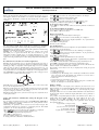
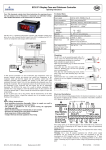
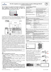
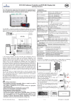
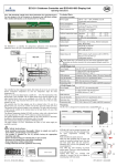
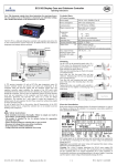
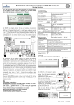
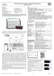
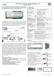
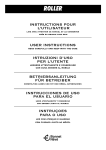
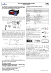
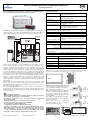
EC3-331 Coldroom Controller and ECD-001 Display Unit
GB
Operating Instructions
Note: This document contains short form instructions for experienced users.
Use last column in List of Parameters to document your individual settlings.
More detailed information can be found in the User Manual.
Technical Data
EC3 Series Controller
Power supply
Power consumption
25VA max. including EX4 … EX7
28VA max. including EX8
Communication
LonWorks® Interface, FTT10, RJ45 connector
Removable screw terminals
wire size 0.14 … 1.5mm2
Plug-in connector size
The EC3-331 is a dedicated controller for refrigerated coldrooms with superheat
control and a driver for an Alco Controls Electrical Control Valve EX4...EX8. In
addition the EC3-331 controls air temperature and manages defrost and fan(s).
24VAC ±10%; 50/60Hz; Class II
6.3mm spade earth connector
Ambient temperature range 0 … 60°C
1 … 25°C (for best battery life time)
> 35°C battery life time < 2 years
! In order to provide system protection in the event of power loss, it is
recommended to change the battery annually.
Humidity
0…80% r.h. non condensing
Protection class
IP20
Pressure transmitter input 24VDC, 4...20mA
4-20 mA analog output
For connection to any 3rd party controller with
12/24VDC power supply and appropriate burden
Deviation from input signal ±8% max
Analog output
24VDC, 4...20mA
Digital Inputs
24VAC/DC
Output relays (4)
Inductive (AC15) 250V/2A
Alarm, Comp SPDT contacts, AgNi, resistive (AC1) 250V/8A
Heater, Fan SPST contacts, AgNi, resistive (AC1) 250V/6A
! If the alarm relay is not utilized, the user must ensure appropriate safety
precautions are in place to protect the system against damage caused by a
power failure.
Stepper motor output
For EX4…EX8 Electrical Control Valves
ECD-001 Display Unit
Power Supply
From EC3-331 via connecting cable
Display
A PT4 pressure transmitter (4) and an ECN-Pxx pipe temperature sensor (1)
measure saturated suction gas pressure and suction gas temperature at the
evaporator outlet and feed the signals into the superheat control loop. The
superheat controller output modulates the opening of the EX4…EX8 Electrical
Control Valve (11) thus optimising the refrigerant mass flow through the
evaporator. The ECN-Sxx air temperature sensor (2) measures air-in temperature at
the evaporator and feeds a signal into the air temperature thermostat. The ECN-Fxx
fin sensor (3) is used for defrost termination. Digital input (5) should be connected
to the serial control loop of a compressor (where applicable) and digital input (6)
should be connected to the coldroom door contact. The controller has 4 relay
outputs to control the compressor (7), defrost heater (8) evaporator fan (10) and an
external alarm device (9). Please consult the technical data (right) for input and
output ratings.
The EC3-331 features an integral backup battery to close the electrical control
valve in case of power loss. Due to the positive shut-off characteristics of the
EX4…EX8 Electrical Control Valves, a liquid line solenoid valve is not needed to
prevent flooding of the compressor.
The optional ECD-001 Display Unit (13) can be connected to the EC3-331 for
local display of control parameters and for controller setup without the use of a PC.
Because the EC3-331 is fully functional without display unit the ECD-001 may be
removed at any time.
!
•
•
•
•
•
•
•
Safety instructions:
Read installation instructions thoroughly. Failure to comply can result in
device failure, system damage or personal injury.
The product is intended for use by persons having the appropriate
knowledge and skills.
Ensure electrical ratings per technical data are not exceeded.
Disconnect all voltages from system before installation.
Keep temperatures within nominal limits.
Comply with local electrical regulations when wiring
The EC3 series contains a lead, acid gel rechargeable battery. The battery
must NOT be disposed of with other commercial waste. Instead, it is the
users responsibility to pass it to a designated collection point for the safe
recycling of batteries (harmonised directive 98/101/EEC). For further
information, contact your local environmental recycling centre.
2½-digit red LED with decimal point
switchable between °C and °F
LED indicators
Compressor, Fan, Defrost, Alarm, IR status
Temp & Humidity
Identical to EC3-331 specifications above
Protection class
Connecting cable
IP65 (front protection with gasket)
ECC-N10 (1,0m) or CAT5 cable with RJ45 connectors
Mounting
The EC3-331 is designed to be mounted onto a standard DIN rail. Mounting
position: on vertical walls, with stepper motor connector on top side only.
ECD-001 can be mounted in panels with a 71
x 29 mm cutout. See dim. drawing below for
space requirements including rear connectors.
Push controller into panel cutout.(1)
Make sure that mounting lugs are flush with
outside of controller housing. Insert Allen key
into front panel holes and turn clockwise.
Mounting lugs will turn and gradually move
towards panel (2)
Turn Allen key until mounting lug barely
touches panel. Then move other mounting lug
to the same position (3).
Tighten both sides very carefully until
controller is secured. Do not over tighten as
mounting lugs will break easily.
Prg
36
6
78
EC3-331_65083_EN_R12.doc
Replacement for Rev.:11
Cutout 71 x 29 mm
Sel
1/4
36.5
PCN 864 912 18.04.2011
EC3-331 Coldroom Controller and ECD-001 Display Unit
Operating Instructions
GB
Electrical Installation
Parameter Modification: Procedure
Refer to the electrical wiring diagram (below) for electrical connections. A copy of
this diagram is labeled on the controller. Use connection wires/cables suitable for
90°C operation (EN 60730-1). Ground the metal housing with a 6.3mm spade
connector.
• Press or to show the code of the parameter that has to be changed;
• Press SEL to display the selected parameter value;
• Press or to increase or decrease the value;
• Press SEL to temporarily confirm the new value and display its code;
• Repeat the procedure from the beginning "press or to show..."
To exit and save the new settings:
• Press PRG to confirm the new values and exit the parameters modification
procedure.
To exit without modifying any parameter:
• Do not press any button for at least 60 seconds (TIME OUT).
• Press “ESC” on IR remote control.
Defrost Activation:
EC3 analog inputs are for dedicated sensors only and should not be connected to
any other devices. Digital inputs should only be connected to 24VAC/DC.
Connecting any EC3 inputs to mains voltage will permanently damage the EC3.
Important: Keep controller and sensor wiring well separated from mains wiring.
Minimum recommended distance 30mm..
Warning: Use a class II category transformer for 24VAC power supply
(EN 61558). Do not ground the 24VAC lines. We recommend to use one
transformer per EC3 controller and to use separate transformers for 3rd party
controllers, to avoid possible interference or grounding problems in the power
supply. Connecting any EC3 inputs to mains voltage will permanently damage the
EC3.
Recommended Sensor Positions for Cold Room Applications:
ECN-Pxx coil-out temperature sensor (1): Position directly after the evaporator on
the common suction line as shown below. Insure proper thermal contact by using a
metallic pipe clamp or temperature resistant plastic straps. Do not use standard
plastic tie wraps (as used for electrical wiring) as they may become loose over
time, which could result in faulty temperature measurements and poor superheat
control performance. It is recommended to insulate the coil-out temperature sensor
with ARMAFLEX™ or equivalent. The recommended position of the pipe sensors
is between 9 and 3 o'clock as shown in the picture.
PT4-07M suction pressure transmitter (4): Position on the common suction line
close to coil-out temperature sensor (1)
ECN-Sxx air temperature sensor (2): Should be mounted on spacers in the middle
of the air duct so that there is airflow around and positioned on the inlet of the
evaporator as high as possible close to the ceiling.
ECN-Fxx fin temperature sensor (3): Position on the evaporator, asymmetric closer
to the expansion valve.
Setup and Parameter Modification Using the Keypad of the
ECD-001
For convenience, an infrared receiver for the optional IR remote control unit is
build-in, enabling quick and easy modification of the system parameters when a
computer interface is not available.
Alternatively, the parameters can be accessed via the 4-button keypad. The
configuration parameters are protected by a numerical password. The default
password is “12”. To select the parameter configuration:
• Press the PRG button for more than 5 seconds, a flashing “0” is displayed
• Press or until the password is displayed (default = “12”),
if password was changed select the new password
• Press SEL to confirm password
The first modifiable parameter code is displayed (/1).
To modify parameters see Parameters modification below.
EC3-331_65083_EN_R12.doc
Replacement for Rev.:11
A defrost cycle can be activated locally from the keypad:
• Press the button for more than 5 seconds, a flashing “0” is displayed
• Press
or
until the password is displayed (default = “12”), if password was
changed, select the new password
• Press SEL to confirm password
The defrost cycle is activated.
Special Functions:
The Clear Alarm function has been replaced by the Special Functions mode. The
Special Functions can be activated by:
• Press and together for more than 5 seconds, a flashing “0” is displayed.
• Press
or
until the password is displayed (default = “12”). If password was
changed, select the new password.
• Press SEL to confirm password
• A “0” is displayed and the Special Function mode is activated.
or
to select the function. The number of special functions is dynamic
• Press
and controller dependent. See list below.
• Press SEL to activate the function without leaving the special function mode.
• Press PRG to activate the function and leave the special function mode.
Most of the Special Functions work in a toggle mode, the first call activates the
function, and the second call deactivates the function.
The indication of the function can only be displayed after exiting the special
function mode.
• 0: Display test function
• 1: Clear alarm messages
• 2: Cleaning mode. The cleaning mode is effectively a manual defrost with the
option of the fans on/off. The cleaning mode should not be used in order to
isolate the application for maintenance purposes.
• 3: Fans only
• 4: Set the electronic control valve to 100% open
• 5: Resets all parameters to the factory default setting. The controller will
indicate “oF” during the reset and the valve will close.
Display of Data:
The data to be shown on the display can be selected by the user. In case of an
alarm, the alarm code is displayed alternately with the selected data. The user can
inhibit the alarm code. Press the SEL button to scroll through all possible
displayable data.
The display will show for one second the numerical identifier of the data and then
the selected data. After two minutes the display will return to the by parameter /1
selected data.
It is possible to temporarily display the values of the different sensors. This is a
useful feature when initially setting-up the system without the aid of the
WebPages. Press the SEL sequentially. The value displayed on the screen
corresponds to the number corresponding to the /1 parameter. Action only valid
when parameter H2 = 3.
IR LED
Logical status of compressor relay
LON activity LED
(only active when service pin is pressed)
Logical status of fan relay
Logical status of defrost heater relay
Alarm condition
2/4
PCN 864 912 18.04.2011
EC3-331 Coldroom Controller and ECD-001 Display Unit
Operating Instructions
GB
List of Parameters
/ DISPLAY PARAMETERS
Min Max Unit Def. Custom
/1 Value to show
0
6
0
0 = Thermostat control temperature with Temp. alignment /C
1 = Defrost termination temperature °C
2 = Coil-in temperature °C calculated from the pressure
3 = Coil-out temperature °C
4 = Calculated superheat °K
5 = Valve opening in %
6 = Displays defrost status
/2 Alarm suppression 0 = off, 1 = on
0
1
0
/5 Temperature Unit
0 = °C, 1 = °F
0
1
0
/6 Decimal point
0 = yes, 1 = no
0
1
0
/7 ECD display during defrost
0
2
0
0 = dF (= defrost mode); 1 = dF + defrost termination temp.
2 = dF + control temperature
/C Temperature alignment for /1=0
-20.0 20.0
K
0.0
A ALARM PARAMETERS
A1 Low temp alarm delay
0
180
min
5
A2 High temp alarm delay
0
180
min
5
A3 Alarm delay after defrost
0
180
min
10
Ad Door alarm delay
0
180
min
2
AH High temp alarm limit
AL 70 °C / K 40
AL Low temp alarm limit
-55 AH °C / K -50
At Alarm limit type
0
1
0
0=absolute temperatures °C; 1= relative temperatures K to setpoint
r THERMOSTAT PARAMETERS
r0 Door contact function (see page 4)
0
15
6
r1 Min. setpoint
-50
r2
°C
-50
r2 Setpoint max.
r1
60
°C
40
r3 Day/night control
0 = off, 1 = on
0
1
1
r4 Thermostat mode
0
4
1
0 = off, no thermostat function, continues cooling air in sensor
monitoring off, no temp. alarms generated
1 = cooling, deadband control
cut in = set-point + difference / cut out = set-point
2 = cooling, modulating thermostat
cut in = set-point / cut out = set-point – difference /2
3 = heating, deadband control
cut in = set-point – difference / cut out = set-point
4 = on, external control using nvi Valve via SNMP. Air sensor
monitoring off. Temperature alarms will be generated
r6 Setpoint night
r1
r2
°C
4.0
r7 Differential night
0.1 20.0
K
2.0
rd Differential day
0.1 20.0
K
2.0
St Setpoint day
r1
r2
°C
2.0
d DEFROST PARAMETERS
d0 Defrost mode
0
2
1
0 = natural defrost, defrost heater not activated
pulsed defrost not possible
1 = forced defrost, defrost heater activated, pulsed
defrost possible
2 = forced defrost, defrost heater activated, pulsed defrost
possible, defrost termination using nviStartUp
d1 Termination by:
0
3
0
0 = termination by temperature,
termination by time will generate an alarm
1 = termination by time,
termination by temperature will generate an alarm
2 = first, what ever comes first time or temperature, no alarm
3 = last, by time and temperature, no alarm
Caution: can generate indefinite defrost periods
d3 Pulsed defrost
0
1
0
0 = off, no pulsed defrost, heaters switched off at defrost termination temperature dt or max. time dP whatever is selected
1 = on, pulsed defrost, dd and dH in use, heaters are switched off at
dH and switched on again at dH – dd
d4 Defrost at startup
0 = no, 1 = yes
0
1
0
d5 Delay power up defrost
0
180
min
0
d6 Pump down delay
0
180
sec
0
Compressor will run during pump down delay while valve is closed
d7 Drain delay
0
15
min
2
d8 Injection delay
0
180
sec
0
Valve is open during injection delay while compressor is not running
EC3-331_65083_EN_R12.doc
Replacement for Rev.:11
dd
dH
dt
dP
dI
du
F
F1
F2
F3
F4
F5
Fd
Ft
C
C0
C1
C2
C3
u
u0
u1
u2
u3
u4
u5
u6
u7
u9
uu
ut
uF
P
P1
I
I0
I1
o0
o1
o2
o3
H
H2
H3
H5
Min Max Unit Def. Custom
Pulsed defrost differential
1
20
K
2
Pulsed defrost setpoint
-40
dt
°C
5
Defrost termination temperature
-40 90
°C
8
Max. defrost duration
0
180
min
30
Defrost interval
0
192
h
8
Start up delay after synch
0
180
min
30
FAN PARAMETERS
Fan startup after defrost by: 0 = on
0
4
0
1 = delayed by time Fd, error on temperature
2 = by temperature Ft, error on time
3 = first, whatever comes first time or temperature, no alarm
4 = last, time and temperature must come, no alarm
Fan during no cooling
0
3
0
0 = on; 1 = off; 2 = delayed by F4; 3 = off, when door open
Fan during defrost
0 = on, 1 = off
0
1
0
Stop delay time
0
30
min
0
Fan during cleaning 0 = off, 1 = on
0
1
0
Fan delay after defrost
0
30
min
0
On temp after defrost
- 40 + 40
°C
0
COMPRESSOR PARAMETERS
Delay first start
0
15
min
0
Cycle time
0
15
min
0
Min. stop time it
0
15
min
0
Min. run time
0
15
min
0
SUPERHEAT PARAMETERS
Refrigerant 0 = R22
1 = R134a
0
7
3
2 = R507 3 = R404A 4 = R407C
5 = R410A 6 = R124
7 = R744A
Correction glide / dp
-20.0 20.0
K
0.0
Glide
= positive values
Pressure drop = negative values
MOP control
0
1
0
0 = MOP off, 1 = MOP on
MOP temperature
-40 40
°C
0
Superheat mode
0
4
1
0 = off, 1 = fixed superheat, 2 = adaptive superheat
3 = fixed superheat slow, 4 = adaptive superheat slow (Rev >=25)
Superheat init setpoint
u6
u7
K
6
Superheat setpoint min
3
u7
K
3
Superheat setpoint max
u6
20
K
15
Start opening delay (Rev >= 23)
0
60
10sec
1
Start opening
10 100
%
30
Valve type
0
3
0
0 = EX4 / EX5, 1 = EX6, 2 = EX7, 3 = EX8
Valve scaling factor
20 100
%
100
uF = 100%, max. valve opening =100%, ECD display =100%
uF = 50%, max. valve opening = 50%, ECD display =100%
ANALOG SENSOR PARAMETERS
Pressure sensor type selection
0
2
0
0 = PT4-07M, 1 = PT4-18M, 2 = PT4-30M
LOGIC PARAMETERS
Logic for compressor safety loop input
0
1
0
0 = 24V input voltage means failure; 1 = 0V input voltage means failure
Logic for door contact input
0
1
0
0 = 24V means door open; 1 = 0V means door open
Logic for alarm relays activated
0
1
1
0 = positive logic; 1 = negative logic
Logic for compressor relays activated
0
1
0
0 = positive logic; 1 = negative logic
Logic for heater relays activated
0
1
0
0 = positive logic; 1 = negative logic
Logic for fan relays activated
0
1
0
0 = positive logic; 1 = negative logic
OTHER PARAMETERS
Display access
0
3
3
0 = all disabled (Caution: access to controller only via the LON network)
1 = Keyboard enabled; 2 = IR remote control enabled
3=
Keyboard and IR remote control enabled
IR access code
0
199
0
Password
0
199
12
3/4
PCN 864 912 18.04.2011
EC3-331 Coldroom Controller and ECD-001 Display Unit
GB
Operating Instructions
Remarks:
r0
0=8
1=9
2 = 10
3 = 11
4 = 12
5
6 = 14
7
13
15
r0 Door contact function
Messages
Cooling
on
off
on
off
on
off
on
off
off
off
---
Temp. alarm
on
on
off
off
on
on
off
off
on
off
Function after delay time Ad
In
door alarm
door alarm
door alarm and temperature alarm on
door alarm and temperature alarm on
door alarm and cooling on
door alarm and cooling on and
temperature alarm on
Id
OF
Alarm Codes
E0
E1
E2
E3
Er
Ab
!
AC
Ad
AE
AF
AH
AL
AM
Ao
Au
dt
Ft
Pressure transmitter alarm
Coil out sensor alarm
Air sensor alarm
Fin sensor alarm
No sensor connected or the sensor and/or the sensor cable is broken or shortcircuited.
Data error display - out of range
Data send to the display is out of range.
Battery health failure
Battery potentially does not have enough charge to close valve in an
emergency. Only reset by replacing battery (Replacement kit: 807 790).
The use of the relay is essential to protect the system in case of power failure
if the communications interface or the ECD-002 are not utilized.
Alarm status of the compressor serial loop feedback
External compressor is active. Serial safety loop is open circuit
Door open alarm
Thermostat emergency operation
Air sensor failure, system is in continuous cooling mode
Valve Status
Valve closed due to compressor safety loop active
High temperature alarm
Low temperature alarm
ECV connection error
Check connections to EX4…8 Electrical Control Valve
Superheat, emergency operation
Sensor(s) failure
Valve open 100% for more than 10 minutes
Forced defrost termination (time or temperature)
Forced fan startup (time or temperature)
Emerson Electric GmbH & Co OHG is not to be held responsible for erroneous
literature regarding capacities, dimensions, applications, etc. stated herein.
Products, specifications and data in this literature are subject to change without
notice. The information given herein is based on technical data and tests which
EMERSON believes to be reliable and which are in compliance with technical
dS
dP
df
dd
dI
du
Cn
CL
No data to display
The display will show an “---” at node start up and when no data is send to
the display.
Reset to default values activated
The display will show an “In” when the factory default configuration data set
is initialized.
Wink request received
The display will show a flashing “Id” when the wink request was received.
The flashing “Id” will be shown on the display until the service button will
be pressed, or a 30 min delay timer will expire or a second wink request is
received.
Node is offline
The node is offline and no application is running. This is the result of a
network management command and will happen for example during node
installation.
Defrost standby
Pump down
Defrost cycle
Defrost drain delay
Defrost injection delay
Defrost start-up delay
Cleaning
Alarms are cleared
Visualising Data: LON Monitoring Server
The EC3-331 has a LON communication interface enabling the controller to be
directly connected to a Monitoring Server. Front view of RJ45 connector:
Neuron ID / Service PIN:
The service pin is available on the ECD display. It is used to identify the controller
in a LON network.
Press the
button for approx. 1 sec. to send the Neuron ID. The LED in the left
upper corner will indicate the transmission of the Neuron ID.
The default settings may be modified remotely from the EMS Monitoring Server
via the LON network. Consult the EMS user manual for more information.
It is also possible to display live graphical data on the server or to log data
containing the control temperature at defined intervals.
knowledge of today. It is intended only for use by persons having the appropriate
technical knowledge and skills, at their own discretion and risk. Since conditions of
use are outside of EMERSON's control we cannot assume any liability for results
obtained or damages occurred due to improper application.
This document replaces all former versions
Emerson Electric GmbH & Co OHG - Postfach 1251 - Heerstraße 111 - D-71332 Waiblingen - Germany - Phone .49-(0)7151-509-0 - Fax .49-(0)7151-509-200
www.emersonclimate.eu
EC3-331_65083_EN_R12.doc
Replacement for Rev.:11
4/4
PCN 864 912 18.04.2011