1
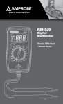
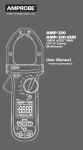
CT-326-C
Current Tracer
Users Manual
Current Tracer
Users Manual
P/N 2757388 Rev 002
11/2013, 6001572 A
© 2013 Amprobe Test Tools. All rights reserved.
English
CT-326-C
Limited Warranty and Limitation of Liability
Your Amprobe product will be free from defects in material and workmanship for one year from
the date of purchase unless local laws require otherwise. This warranty does not cover fuses,
disposable batteries or damage from accident, neglect, misuse, alteration, contamination, or
abnormal conditions of operation or handling. Resellers are not authorized to extend any other
warranty on the behalf of Amprobe. To obtain service during the warranty period, return the
product with proof of purchase to an authorized Amprobe Service Center or to an Amprobe
dealer or distributor. See Repair Section for details. THIS WARRANTY IS YOUR ONLY REMEDY.
ALL OTHER WARRANTIES - WHETHER EXPRESS, IMPLIED OR STATUTORY - INCLUDING IMPLIED
WARRANTIES OF FITNESS FOR A PARTICULAR PURPOSE OR MERCHANTABILITY, ARE HEREBY
DISCLAIMED. MANUFACTURER SHALL NOT BE LIABLE FOR ANY SPECIAL, INDIRECT, INCIDENTAL
OR CONSEQUENTIAL DAMAGES OR LOSSES, ARISING FROM ANY CAUSE OR THEORY. Since
some states or countries do not allow the exclusion or limitation of an implied warranty or of
incidental or consequential damages, this limitation of liability may not apply to you.
Repair
All Amprobe returned for warranty or non-warranty repair or for calibration should be
accompanied by the following: your name, company’s name, address, telephone number, and
proof of purchase. Additionally, please include a brief description of the problem or the service
requested and include the test leads with the meter. Non-warranty repair or replacement
charges should be remitted in the form of a check, a money order, credit card with expiration
date, or a purchase order made payable to Amprobe.
In-warranty Repairs and Replacement – All Countries
Please read the warranty statement and check your battery before requesting repair. During
the warranty period, any defective test tool can be returned to your Amprobe distributor for
an exchange for the same or like product. Please check the “Where to Buy” section on www.
Amprobe.com for a list of distributors near you. Additionally, in the United States and Canada,
in-warranty repair and replacement units can also be sent to an Amprobe Service Center (see
address below).
Non-warranty Repairs and Replacement – United States and Canada
Non-warranty repairs in the United States and Canada should be sent to an Amprobe Service Center.
Call Amprobe or inquire at your point of purchase for current repair and replacement rates.
USA: Canada:
AmprobeAmprobe
Everett, WA 98203 Mississauga, ON L4Z 1X9
Tel: 877-AMPROBE (267-7623) Tel: 905-890-7600
Non-warranty Repairs and Replacement – Europe
European non-warranty units can be replaced by your Amprobe distributor for a nominal charge.
Please check the “Where to Buy” section on www.Amprobe.eu for a list of distributors near you.
Amprobe Europe*
Beha-Amprobe
In den Engematten 14
79286 Glottertal, Germany
Tel.: +49 (0) 7684 8009 - 0
www.Amprobe.eu
*(Correspondence only – no repair or replacement available from this address. European customers please contact
your distributor.)
1
P26 Receiver
1) Probe tip
2
2) LED bar-graph indicator
3
3) Battery status check
4) Range switch
5) ON test mode: Push and hold
to test
4
6) Battery test: Push and hold to
check battery status
6
5
7) Earphone jack
8) Battery compartment
R
R
7
8
2
1
T300 Transmitter
1) LED indicator
2) Fuse compartment
3) Pigtail and power cord adapter
R
R
3
3
CT-326-C Current Tracer
Contents
SYMBOLS...................................................................................................................... 5
INTRODUCTION............................................................................................................ 5
SYMBOLS AND WARNINGS.......................................................................................... 5
UNPACKING AND INSPECTION.................................................................................... 6
COMPONENTS DESCRIPTION....................................................................................... 6
T300 (6-300 V) Transmitter...................................................................................... 6
P26 Receiver............................................................................................................. 6
OPERATION................................................................................................................... 7
Transmitter Test Position......................................................................................... 7
Receiver Sensitivity.................................................................................................. 7
Distance from wire for half scale reading approximate....................................... 8
Receiver Test Position.............................................................................................. 8
Circuit Breakers, Fuses............................................................................................. 9
Neutral Lines within a Breaker Panel................................................................... 10
Phases, Main Breakers, Transformers, Switch Gear. 300 V Max.......................... 10
Wires in Floors, Walls, Ceilings............................................................................. 11
Conduit.................................................................................................................. 12
Underground Wires and Buried Cables................................................................ 13
Underground Wire, Buried Cables Using an Independent Power Supply......... 13
Neutral Wires and Ground Wires......................................................................... 14
Open Breakers....................................................................................................... 14
Wire to Wire Shorts............................................................................................... 15
Shorts to Ground................................................................................................... 15
Computer Coax Gables.......................................................................................... 15
Transmitter Fuse Replacement.............................................................................. 16
Receiver Battery Replacement.............................................................................. 16
Troubleshooting the Current Tracer..................................................................... 17
SPECIFICATIONS.......................................................................................................... 17
4
Symbols
�
�
�
�
Refer to the manual
Alternating current
�
�
�
�
�
Conforms to relevant Australian
standards.
�
Complies with EU directives
�
Do not dispose of this product as
unsorted municipal waste.
�
Underwriters Laboratories.
�
Application around and removal from hazardous live conductors is permitted
Battery
Double insulated
Direct current
Dangerous voltage
Earth ground
Audible tone
Introduction
The Amprobe PASAR Current Tracer is a hand-held circuit tracing device for locating and tracing
circuit breakers and “hot” and neutral conductors without turning off power or interrupting
sensitive electronic equipment.
The current tracer consists of a transmitter and a receiver for tracing 6-300 V circuits, ac or
dc. The transmitter, when connected to a power source, draws short bursts of high frequency
current (0.25 amp peak load at 6.25 KHz) from the power line 71 times per minute. The receiver
detects the resulting magnetic field surrounding the conductors that supply power to the
transmitter. With custom digital filtering, the receiver visually and audibly indicates which circuit
is carrying the transmitter’s low ampere, high frequency load.
There are no distance limitations with the current tracer since it works by drawing a small load
current from the power source and not by injecting an RF signal. Furthermore, this keeps the
current tracer’s signal confined to the circuit to which it is applied instead of “bleeding off’ onto
other circuits. Therefore, the signal will travel from the transmitter to the source of power (the
power generating station) and back on the neutral, totally unaffected by distance. It’s quick,
easy and safe to use!
��
WARNINGS AND PRECAUTIONS
1. To avoid possible electrical shock or personal injury, follow these instructions and use the
tester only as specified in this manual.
2. Read this manual in its entirety before proceeding with any testing.
3. This equipment should only be used by trained professionals who are familiar with electrical
hazards.
4. Wear lineman gloves, safety glasses, and protective clothing at all times.
5. Before using any electrical instrument, it should be checked to make certain it is operating
properly.
6. In many instances, you will be working with dangerous levels of voltages and/or current,
therefore, it is important that you avoid direct contact with any uninsulated, current carrying
surfaces. Appropriate insulated gloves and PPE clothing should be worn.
5
7. Before attaching any of the conductors, make sure the voltage presence is not beyond the
range of the instrument.
8. When not in use, keep the instruments in their carrying case.
9. If the CT-326-C will not be used for a period of time, remove the battery to prevent leakage
in the instrument.
Unpacking and inspection
1 x P26 Receiver
1 x T300 Transmitter
1 x Pigtail connector: PT26
1 x Power cord (T300): PC-326
1 x Adapter: AD-1
1 x Earphone, 3.5mm: EP1001
1 x Fuse, ¼ amp, 250V, Fast acting: 3AG-312.250
1 x Soft carrying case: CC-326
ComponentS Description
T300 (6-300 V) Transmitter
�CAUTION: Do not connect the transmitter to a separate ground in electrically susceptible
patient areas of a health care facility.
�CAUTION: Make the ground connection first and disconnect it last when using the pigtail
connector.
The T300 Transmitter is designed for tracing 6-300 V ac or dc circuits by drawing a high
frequency load currents from a power source, thus creating a traceable magnetic field around
the conductors supplying its power (see Fig. 2). The transmitter houses a crystal controlled digital
circuit that never needs adjusting, and will not interfere with sensitive electronic equipment on
the line.
Transmitter Signal
When properly connected to the circuit to be traced, the red LED on the fuse end of the
transmitter blinks at a steady rate of 71 times per minute. This indicates that the transmitter is
operating, and that there is power on the line.
P26 Receiver
The P26 Receiver is a tuned magnetic field strength meter. When waved over conductors or
circuit breakers, the sensor in the receiver’s tip ignores other line current fluctuations and
identifies the conductors feeding power to the transmitter.
The probe provides both audible and visible indications when it’s within range of the wires or
circuit breakers supplying power to the transmitter. The audio indication is a 3.125 KHz tone. The
visual indication is provided by a 10- position LED display. An earphone is included for use with
the probe when background noise makes the audio indication difficult to hear.
6
Operation
Transmitter Test Position
IMPORTANT: For locating and tracing
applications, always use a voltmeter to
determine the line voltage before connecting
the transmitter.
1. Plug the transmitter into any standard
electrical outlet (see Fig.1). If there is no
outlet available, use the pigtail connector
provided.
2. Verify that the transmitter’s red LED is
blinking.
3. If the LED is not blinking, confirm whether or
not the outlet is energized with a voltmeter.
The transmitter must be able to draw current
in order to operate.
Fig.1
4. If the LED is not blinking and the outlet has
been confirmed to be energized, remove
the Transmitter from the outlet and check
the fuse located on the LED end of the
transmitter. The transmitter may have an
open fuse if it has been attached to voltages
higher than its range.
Receiver Sensitivity
Strong Signal
Weak Signal
R
2. Position of the range switch: If the probe
displays 10 LEDs, the gain is too sensitive
(except in the test position). Turn the range
switch to a lower setting.
3. Battery: Change the probe’s battery if the
battery test does not cause the LEDs to light
within the “Battery OK” area.
R
1. Angle of the receiver: The receiver’s tip must
be held perpendicular to the conductor in
order to allow the conductor’s magnetic
field and the receiver’s sensor to couple most
effectively.
R
R
The receiver’s range switch determines the
probe’s gain - receiver sensitivity depends on
three elements:
Receiver probe's tip must be
perpendicular to the wire
Fig.2
7
RANGE SWITCH
APPLICATIONS
WIRES (most selective)
Locate conductor in bundles and conductors entering a breaker switch
BREAKERS
Locate individual circuit breaker switches and test position
SCAN
Locate conductors in floors, walls, ceilings, and conduit and correct
breaker panels
LONG RANGE
(most sensitive)
Locate underground cables and wire to wire shorts
Receiver Range and Applications
P26 Receiver Gain Using Looped Wire Test Setup
Distance from wire for half scale reading approximate
Range Setting
in/ft
cm/m
Relative Gain
1 Wires
1.5 in
3.8 cm
X1
2 Wires
2.5 in
6.4 cm
X2
3 Breakers
4.0 in
10.2 cm
X3
4 Breakers
6.0 in
15.2 cm
X5
5 Breakers
10.0 in
26.7 cm
X10
6 Scan
18.0 in
45.7 cm
X25
7 Scan
2.5 ft.
0.8 m
X50
8 Scan
3.8 ft.
1.1 m
X90
9 Scan
6.0 ft.
1.8 m
X160
10 Scan
7.5 ft.
2.3 m
X240
11 Long Range
11.0 ft.
3.3 m
X450
12 Long Range
13.0 ft.
3.9 m
X850
8
Receiver Test Position
1. To test the receiver’s battery, push the “Battery Test” button. If the LED display does not light
up within the “Battery OK” area, replace the battery and repeat.
2. Turn the receiver’s range switch to “Breakers-5.”
3. Press “ON” and wait 2 seconds for the receiver to calibrate. Holding the calibrated receiver,
touch its tip to the front and center of the operating transmitter (see Fig. 1). Ten LEDs will
flash brightly, in sequence from left to right, at the same rate as the transmitter’s LED,
indicating that the receiver is working correctly. This flashing LED response from the probe is
what you will be looking for as you trace circuits.
Circuit Breakers, Fuses
1. Plug the transmitter into an outlet, or attach with the insulated clip leads of the pigtail
connector to the conductors you want to identify.
2. Turn the receiver’s range switch to “scan-5.”
3. Press the receiver’s “ON” button and wait for it to calibrate
4. Wave the receiver’s tip slowly outside the closed panel box door and observe the receiver’s
signal. As the probe approaches the correct panel box, the audio indication becomes louder
and the LEDs will flash. Use the receiver’s earphone, If necessary, to hear the signal.
5. The correct panel box produces the strongest signal. Not all LEDs need to flash in order to
signal the correct panel. However, if the probe’s signal is of equal intensity on more than
one panel, the gain may be set too high. Turn the range switch to a lower setting, I.e.,
“Breakers-3.”
6. Open the panel box door.
7. Turn the receiver’s range switch to “Breakers-4.”
8. Press the receiver’s “ON” button and wait for it to calibrate.
9. Touch the receiver’s tip to each circuit breaker as shown in Fig.3
10.The receiver’s tip must be held at the correct angle to the breaker to ensure accuracy. As the
receiver approaches the correct breaker, the audible indicator becomes louder and the LEDs
will flash.
11.The breaker controlling the circuit being traced produces the strongest signal. Not all LEDs
need to flash in order to signal the correct breaker. However, if the receiver’s signal is of
equal intensity on more than one breaker, the gain may be set too high. Turn the range
switch to a lower setting, i.e., “Breakers-3” or “Wires-2.”
12.Remove the panel trim.
13.Turn the receiver’s range switch to “Wires-1.”
14.Press the receiver’s “ON” button and wait for it to calibrate.
15.Touch the receiver’s tip on the wire connected to breaker previously identified. The receiver’s
tip must be held at the correct angle to the wire to ensure accuracy. Only the wires that the
transmitter is attached to will produce a signal.
9
Fig.3 Correct the angle of the probe for
accurate readings
Neutral Lines within a Breaker Panel
Neutral lines may also be traced since the magnetic signal produced by the transmitter returns
on the circuit’s neutral line.
Follow steps 1-15
16.With the panel trim removed and the receiver’s range switch set on “Wires-1,” touch the
receiver’s tip to the neutral wires in the breaker panel. The receiver will indicate only on the
neutral of the circuit to which the Transmitter is attached.
Phases, Main Breakers, Transformers, Switch Gear. 300 V Max.
Since the Transmitter signal is current drawn from the power line, it will travel from the
transmitter to the source of power and back on the circuit’s “hot” and neutral lines, totally
unaffected by distance. Therefore, the receiver will be able to detect the phase that bears the
circuit to which the transmitter is attached, i.e., the remote main breaker, the utility box, the
transformer, the switch gear, etc. These do not have to be in the same building or on the same
floor as the location of the circuit where the transmitter is attached.
As the transmitter’s signal passes through transformers, it is affected only by the step-up or
step-down ratio of the transformer. For example, if the signal passes through a 2:1 step-down
transformer, the signal will be reduced by one half.
When tracing the path of the circuit through transformers, it may be necessary to set the
receiver’s range switch to a “Long Range” position.
Fig.4
10
Wires in Floors, Walls, Ceilings
IMPORTANT: Since the load current on the conductors supplying power to the transmitter flows
in opposite directions on the “hot” and neutral wires, the magnetic field surrounding these
conductors radiates in the opposite direction. (See Fig. 6). Therefore, when the “hot” and
neutral wires are within close proximity, they tend to cancel the force of each other’s magnetic
field. For this reason, it is advisable to separate the current paths in order to trace them. The
easiest and most effective way to do this is to use a separate ground, not adjacent to the ground
of the circuit being traced, to provide a current path back to the power source.
1. Plug the pigtail connector into the transmitter
2. Attach one of the pigtail connector’s insulated clip leads to a separate ground, such as a
water pipe (see Fig. 5). As an alternative, use the neutral wire from another circuit away from
the circuit being traced.
3. Attach the other lead to the “hot” conductor of the circuit you wish to trace. The
transmitter’s LED will blink to indicate it is operating and that the circuit is complete.
4. Turn the receiver’s range switch to “Scan-8.”
5. Press the receiver’s “ON” button and wait for it to calibrate.
6. Hold the receiver’s tip close to the floor, wall, or ceiling where you suspect the conductor is
located.
7. Sweep the receiver across large areas until the receiver’s signal locates the conductor. Narrow
down the location of the conductor by changing the angle of the receiver and adjusting the
range switch as necessary.
I
I
Fig.5 Separate ground connection
Fig.6 Direction of load current on conductors
NOTE: Be sure to follow the “hot”
conductor and not the ground path or
neutral wire used to supply power to the
transmitter.
11
Individual Wires within Bundles
When tracing wires bundled together, it may be necessary to separate them to reduce magnetic
coupling to nearby wires (see p.12).
Conduit
1. Plug the pigtail connector into the transmitter.
2. Attach one of the pigtail connector’s insulated clip leads to a separate ground such as a water
pipe. Be sure the ground path you choose is not adjacent to the conduit you wish to trace.
3. Attach the other lead to the “hot” conductor that runs inside the conduit you wish to trace.
The transmitter’s LED will blink to indicate it is operating and that the circuit is complete.
4. Turn the receiver’s range switch to “Scan-6.” Since conduit will frequently cause the signal to
become weaker, turn the receiver’s range switch to a higher gain as necessary.
5. Press the receiver’s “ON” button and wait for it to calibrate
6. Hold the receiver’s tip close to the location where you suspect the conduit runs.
7. Sweep the receiver across large areas until its signal locates the conduit. Narrow down the
location of the conduit by adjusting the range switch (see Figs. 7) and changing the angle of
the receiver.
Fig.7 Receiver distance from
circuit breaker panel when
tracing conduit
NOTE: Be sure you are following the “hot” conductor within the conduit and not the ground
path or neutral wire used to complete the circuit. Do not use the conduit if you wish to trace for
the ground connection.
Since the feeder panel may radiate the magnetic field to the nearby conduit, make sure the
probe is always used more than 5 feet (1.5 meters) away from the circuit breaker panel during
this application (see Fig.7).
12
Underground Wires and Buried Cables
1. Plug the pigtail connector into the transmitter.
2. Attach one of the pigtail connector’s insulated clip leads to a separate ground such as a metal
rod planted in the earth.
3. Attach the other lead to the “hot” conductor of the circuit you wish to trace. The
transmitter’s LED will blink to indicate it is operating and that the circuit is complete.
4. Turn the receiver’s range switch to “Scan-12.”
5. Push the receiver’s “ON” button and Walt for it to calibrate.
6. Hold the receiver over the surface and walk in the area where you suspect the conductor is
located (see Fig.8). If this is unknown, walking a large arc in the suspected area while keeping
in mind the orientation of the receiver’s tip to the conductor.
7. Once a signal has been detected, follow it until the maximum reading of LEDs is found.
Narrow down the location of the conductor by changing the angle of the receiver and
adjusting the range switch as necessary. Remember that the probe’s signal will vary as
the conductor’s depth varies. The conductor will be located where you have the strongest
indication.
8. Repeat this procedure from the opposite end of the conductor to insure the correct location.
NOTE: Be sure you are following the cable you wish to trace and not the ground path used to
complete the circuit.
Fig.8
Underground Wire, Buried Cables Using an Independent Power Supply
�WARNING! - To use this method the conductor must not be energized.
1. Plug the pigtail connector into the transmitter.
2. Attach one of the pigtail connector’s insulated clip leads to a separate ground such as a metal
rod planted in the earth. If the optional wire loop is used, a separate ground is not needed.
3. Attach the other lead to a power source, i.e. a battery pack. Connect the power supply to the
conductor you wish to trace.
4. Turn the receiver’s range switch to “Wires-1”
13
5. Press the probe’s “ON” button and wait for it to calibrate.
6. Place the tip of the receiver to the grounded side of the transmitter. The receiver should
indicate a full scale reading of 10 LEDs. If the receiver does not indicate this, the voltage that
is being applied will have to be increased or total resistance of the circuit will have to be
reduced.
NOTE: Soil has minimal effect on the magnetic field created by the T300 transmitter. However,
the signal will be reduced by as much as 50% when the return path is through ground due to the
cancellation effect of the return signal. Typically, more voltage will be needed for dry soil and/or
longer conductor lengths. Refer to the application notes of the CT-326-C to find the voltage that
must be applied to the transmitter to overcome the effects of resistance and Inductance of the
circuit to develop acceptable signal strength.
Neutral Wires and Ground Wires
1. Plug the pigtail connector into the transmitter.
2. Attach one of the pigtail connector’s insulated clip leads to the circuit’s neutral or ground.
3. Attach the other lead to a grounded 9 V battery (see Fig.9) as an alternative, clip the other
lead to the “hot” side of any grounded 6-300 V power source. For example, an extension cord
that is plugged into an energized outlet works well.
4. The transmitter’s LEDs will blink if the neutral wire is connected at the panel allowing the
circuit to be traced.
5. Trace the neutral or ground wires with the receiver as explained in “Wires in Floors, Walls,
Ceilings and Conduits.”
NOTE: Be sure to follow the neutral or ground wire and not the “hot” conductor from the circuit
used to supply power to the transmitter.
Open Breakers
1. Attach the transmitter and use the probe to trace the neutral wire on the dead circuit as
explained in steps 1-5 for neutral wires, ground wires.
2. When you can see the panel box, discontinue the above method and locate the correct circuit
breaker panel and the neutral line within the panel as explained in “Circuit Breakers and
Fuses.”
3. Visually locate the neutral’s corresponding “hot” wire and circuit breaker. Use a voltmeter to
verify the open breaker.
Fig.9
14
Wire to Wire Shorts
1. Use an ohmmeter to locate the shorted pair of conductors.
2. Disconnect the conductors from power.
3. Plug the pigtail connector into the transmitter.
4. Attach one of the pigtail connector’s insulated clip leads to either of the shorted conductors.
5. Attach the other lead to either pole of a 9 volt battery (or other power source).
6. Connect the other pole of the battery to the other shorted conductor.
7. The transmitter’s LED will blink to indicate that it is operating and that current is flowing
from the battery, through the Transmitter, and returning on the shorted conductors.
8. Turn the receiver’s range switch to “Long Range-9)
9. Press the receiver’s “ON” button and wait for it to calibrate.
10. Holding the probe’s tip as close to the shorted conductors as possible, move away from the
transmitter. Observe the receiver’s LEDs for a dramatic change in signal strength. This will be
the location of the short.
NOTE: For best results, it may be necessary to remove loads from the shorted circuit.
Shorts to Ground
1. Locate the tripped circuit breaker and make sure the switch is in the OFF position. You may
be able to locate the tripped breaker by using the methods described in “Open Breakers”
2. lug the pigtail connector into the transmitter.
3. Attach one of the pigtail connector’s insulated clip leads to the shorted power line.
4. Attach the other lead to the “hot” conductor of an adjacent breaker. As an alternative,
attach this lead to a grounded 9 volt battery or other power source.
5. The transmitter’s LED will blink to indicate it is operating and that current is flowing from the
adjacent breaker or power source through the transmitter, using the shorted line as a neutral,
and going to ground where the short occurs.
6. Turn the receiver’s range switch to “Scan-6.’
7. Press the receiver’s “ON” button and wait for it to calibrate
8. Holding the receiver’s tip close to the shorted wire, move away from the transmitter. Observe
the receiver’s LEDs for signal strength.
Computer Coax Gables
1. Plug the pigtail connector into the transmitter.
2. Attach one of the pigtail connector’s insulated clip leads to the shield of the coax cable.
3. Attach the other lead to a grounded 9 volt battery.
15
4. The transmitter’s LED will blink to indicate that it is operating and that the circuit is complete
(see Fig. 10). It is not necessary to disconnect the coax cable for this application. If the coax
is connected, signal will travel toward ground in both directions and the strength will be
reduced by one half.
5. Adjust the receiver’s range switch as necessary; depending on access to the cable during the
search.
6. Press the receiver’s “ON” button and wait for it to calibrate.
7. Trace the coax cable with the receiver as explained in “Wires in Floors, Walls, and Ceilings.”
NOTE: Make sure the coax shield is grounded at the distant end. Check with the computer
operator before disconnecting active computer cables.
Fig.10
Transmitter Fuse Replacement
Disconnect Instrument from power before replacing the fuse. Use a flat blade screwdriver to turn
the fuse cap 1/4 turn counterclockwise. The fuse carrier and the fuse will pop out. Remove the
fuse and replace it with the same type of 0.25 amp, 250 V normal blow fuse. (An extra fuse has
been provided in the carrying case.) Push the fuse and the fuse carrier back into the transmitter
using the screwdriver, and turn the cap clockwise until it locks.
Receiver Battery Replacement
The battery in the receiver should be tested before each use. To test the battery, push the
“Battery Test” button. The LED readout should light up within the “Battery OK” section of the
display. If it does not, replace the battery.
To replace the battery, hold the receiver face down and push the battery compartment door
catch upward with your thumb; the battery cover should pop up exposing the battery. To remove
the battery, strike the back of the receiver sharply in the palm of your hand. The replacement
battery can then be inserted. Use a 9 V alkaline battery only. DO NOT FORCE THE BATTERY.
Observe the picture of the battery in the compartment as a guide to insert the battery correctly.
Replace the battery door and be sure to perform the battery test procedure after the new
battery is installed.
16
Troubleshooting the Current Tracer
To test the operation of the transmitter, connect it to a known power source from 6 to 300 V ac/
dc. The LED should begin to blink at a steady rate of approximately 71 times per minute. If it
does not blink, checks to ensure that there is proper voltage on the line and replace the fuse,
if necessary. If the LED still does not blink after checking the voltage and the fuse, send the
transmitter In for repair.
Select “Breakers-5” and hold the receiver’s tip to the front and center of the transmitter. Push
the “ON” button and wait 2 seconds for the probe to calibrate. After calibration, 10 LEDs should
flash from left to right in sync with the LED on the transmitter. If it does not, the battery may be
low. After replacing the battery and the LEDs still do not flash, send the probe in for repair.
Specifications
Operating frequency: 6.25 kHz
Operating temperature: 0°F to 120°F (-18°C to 49°C)
Storage temperature: -40°F to 150°F (-40°C to 66°C)
T300 Transmitter fuse: ¼ amp, 250V, fast acting (5x20mm)
Case operating voltage: Flame resistant ABS plastic 6-300 V ac/dc
Operating frequency: 6.25 kHz
Line frequency range: dc to 1 kHz
Maximum load: 200 mA peak at 110 V
Duty cycle: .164 second every .82 second
P26 Receiver
Power: 9 V Alkaline battery IEC #6LR61
Battery life: 100 hours (typical)
Case: Flame resistant ABS plastic
50/60 Hz Rejection: -156 dB to 20K amps @ 50/60 Hz
Accessories and replacement parts
Pigtail connector: PT26
Power Cord (T300): PC-326
Adapter: AD-1
Earphone, 3.5mm: EP1001
Fuse, ¼ amp, 250V, Fast Acting: 3AG-312.250
Carrying case: CC-326
17
Visit www.Amprobe.com for
•
•
•
•
Catalog
Application notes
Product specifications
User manuals
Amprobe®
www.Amprobe.com
[email protected]
Everett, WA 98203
Tel: 877-AMPROBE (267-7623)
Amprobe® Europe
Beha-Amprobe
In den Engematten 14
79286 Glottertal, Germany
Tel.: +49 (0) 7684 8009 - 0
Please
Recycle