Transcript
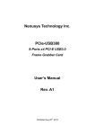
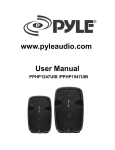
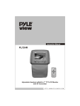
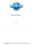
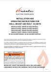
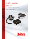
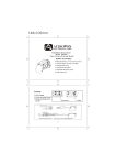
Owner's Manual
Page 2
WNER'S MANUAL
PVCKT5
www.pyleaudio.com
This volume control is designed to run multiple pairs of speakers without damaging your amplifier or receiver. The adjustment is made by using
bridge clips that can be easily changed. NOTE: Both bridge clips must have the sam e setting - i.e. 1x, 2x or 4x. Failure to properly set the
bridge clips may result in damage to your amplifier or receiver. Please follow the recommendations in this section carefully. Failure to
properly set the bridge clips may result in damage to your amplifier or receiver.
Use the chart in Figure #4 to determine a ) the maximum number of speaker pairs that can be connected to your amplifier or receiver and b) the
appropriate bridge clip setting (1 x, 2x or 4x) to use on the volume control.
Impedance Matching Stereo Volume Control
In troduction
This is a wall mounted impedance matching stereo volume control, which connects between the speaker level output of
an amplifier, receiver or speaker selector and a pair of speakers.
Volume Control Placement
When deciding where the volume control will be mounted in the wall, consider the various ways it will be used. The
primary listening area and the ease of running the wire to your chosen location are the important things to keep in mind.
The most common locations to mount volume controls are by the door as you walk into the room, next to existing wall
fixtures, or in the area that you will be listening to music. If you do not understand any part of these instructions, please
contact your system dealer. Improper wiring could cause damage to your audio system.
Do not put the volume control into the same box
as a 110v AC circuit. (i. e. light switch, electrical
outlet, etc.). Speaker wires can act as an "antenna"
for electrical noise. Locating speaker wires too close
to a light switch or dimmer may cause a buzzing or
popping sound to be heard through the speakers. If
you must locate the volume control near electrical
devices, use a separate electrical box.
1. In the first column, determine the minimum impedance capability
Number of Bohm Speaker Pairs
of your amplifier or receiver.
2. Move across the row to the number of 80hm speaker pairs you
wish to use.
3. The resulting number (1 x, 2x or 4x) is the bridge clip setting
appropriate for your configuration. NOTE: Both bridge clips
must have the same setting.
4. The gray area indicates a setting that is slightly below the
amplifier or receiver 's minimum impedance but will most likely
work.
Figure #4
Figure #1
Figure #5
-~'"-'
111
Once a location has been chosen, you may install
the volume control after you have first installed a
standard single gang plaster ring, or a single gang
electrical box (light switch type) .
//
IIt~Ch ..... " • • I
~ IFl. 0Il. ~
Mounting the Volume Control
W
/ /'
l c
. Il. Il. 11"'''''. 1
OL. Ol.
Once the control has been wired, it is ready to be mounted
in to the wall. Referring to Figure #5, place the components
of the volume control into the wall in the order illustrated.
Use the enclosed screws to hold the components in place.
STEP 1
STRIP SPEAKER OR AMPUFIER
WIRE'S INSULATI O N TO 1/ 4"
FROM THE END AND INSERT
INTO PROPER SLOT
SPEAKER WIRE
/
NOTE: The rotary switch is shipped with the control turned
as far counterclockwise as it will turn off. If you changed this,
return it to the full counterclockwise position before starting
installation.
vsr4 5 VOLUME CONTROL
Wiring the Volume Control
(supplied)
CAUTION: Please make sure your amplifier or
receiver is turned off before proceeding.
DECORATOR PLATE (supplied)
STEP 2
TIGHTEN WIRE CLAMP
KNOB (supplied)
SCREW WITH SC REWDRIVER
DECORATOR COVER PLATE (supplied) ~
COVER PLATE SCREWS
(supplied)
This volume control can be used with up to 14-gauge wire.
Measure the distance from the speaker to the amplifier. For distances of
50 feet or less, use 18-gauge speaker wire or ordinary lamp cord. For
distances greater than 50 feet, use heavier 16-gauge wire.
For best results, strip the speaker wire no more than 114" from the end.
Loosen the screws on the underside of the wire block terminal to allow
the wire to be pushed completely into the opening, then tighten the
screws to secure the wire. (See Figure #1). If you need to remove the
wire, simply loosen the screws on the underside of the wire block terminal.
Figure #2
SPEAKERS
••
AMPLIFIER
Speaker
Outputs
RRLL
+ . + -
RIGHT
LEFT
•
•
INPUT
WIRES
Refer to Figure #2 when wiring the volume con t rol:
1. Connect the amplifier or receiver s left speaker output to the left input
terminals on the removable wire block terminal. Please observe proper
polarity of the connections (+ amplifier to + input on the volume
contron.
OUTPUT
WIRES
2. Repeat step 1 for the right side .
SIDE VIEW
VOLUME
CONTROL
3. Connect the wires from the left speaker to the left speaker output
terminals on the wire block terminal. Please observe proper polarity of
the wires for correct speaker phase (+ speaker to + output).
4. Repeat step 3 for right speaker connection.
CAUTION: If the input and output connections are reversed, the minimum
setting on the volume control will cause a short across the amplifier or
receiver output terminals, resulting in serious damage to your amplifier or
receiver. Please double check steps 1 through 4. This volume control
cannot be connected in series with another volume control.
Adjusting the Bridge Clips for Multi ple Speakers (See Figure #3)
Figure #3
2x
1x
Setting
Setting
4x
Setting
Both Clips
on Top
(1x) Pins
Both Clips
on Midd le
(2x) Pins
Both Clips
on Bottom
(4x) Pins