1
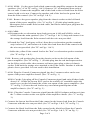
LESLIE CONSOLE CONNECTOR KIT 8253
INSTALLA TION INSTRUCTIONS
FOR USE WITH: HAMMOND Models A100, M100, or E100
LESLIE Speaker 251 or 351
MULTIPLE SPEAKER INSTALLATION: For complete information, see the service manual
of the LESLIE Speaker to be added.
Contents of Kit:
1
1
1
1
1
2
4
8
2
2
5
-Console Connector
-Console Adapter
-6 Conductor Cable
-Oiler
-Instructions
-Screws, 8 x 1/2
-Screws, 6 x 1/2, Blk Oxide
-Wire Nuts
-Connector, Tab, Male
-Connector, Tab, Female
-Insulated Staples
011874
062091
017277
053025
034686
029132
029124
028076
029371
029389
028464
1 -Tremolo Control
024976
Brown
024984
Ebony
024992
Ivory
1 -Echo Control
011882
Brown
011890
Ebony
011908
Ivory
To Install the Kit:
1. Attach the Echo and Tremolo controls to the wooden rail in front of the lower
manual with the black oxide screws provided. Use the two mounting holes which
best center the screws in the rail.
2. Remove the console dust cover, and pass the control cables into the console by
one of the following methods:
A100, M100: Clip the red and green interceptor plugs and sockets off the Echo
control cable and strip the wires 3/8". Push a small screwdriver over the felt
dust seal between the lower manual and the knee panel. Push the cables through
this opening into the console. From the back of the console, reach behind the
tone generator and pull the cables through .
E100: Remove the knee plate under the lower manual, and pass the control cables
into the console through this opening. Cut a small notch in the edge of the knee
plate to accommodate the cables, then replace it.
3. Pass the switch cables through the slot in the rear edge of the shelf into the lower
compartment.
4. Position the console connector near the power amplifier, so that the power and
control cables will reach. Install it with the wood screws provided.
Page 1 of 4
5. A100, M100: Cut the green lead which connects the amplifier output to the main
speakers. (See "A" & "B" on Fig. 1 & 2.) Remove 3/8" of insulation from each of
the cut ends. Connect the amplifier end of this lead to the red lead from the Echo
control with a wire nut. Connect the speaker end of the lead to the green lead
from the Echo control. (See "B" on Figs. 1 & 2.)
E100: Remove the green speaker plug from the chassis socket on the left-hand
apron of the power amplifier. (See "A" on Fig. 3.) Fit this plug intothe green
interceptor socket onthe Echo switch cable, and fit the interceptor plug into the
chassis socket.
6. A100, Ml00:
a Disconnect the reverberation input lead (green on A100 and M100A; red on
M100) from the main speakers. (See "C" on Figs. 1 & 2.) Strip and connect it to
the orange lead from the Echo control with the wire nut provided.
b Detach the "hot" lead (gray or blue) from the reverberation speaker terminal,
strip it about 3/8", and connect it to the blue lead from the Echo control with
the wire nut provided. (See "D" on Figs. 1 & 2.)
c Solder the yellow Echo control lead to the "hot" reverberation speaker terminal.
(See "E" on Figs. 1 & 2.)
E100: Remove red speaker plug from the chassis socket on the left apron of the
power amplifier. (See "B" on Fig. 3. ) Fit this plug into the red interceptor socket
on the Echo switch cable; then connect red interceptor plug to the red chassis
socket. Fold back the orange wire attached to the Echo switch. Insulate it with the
plastic sleeve provided. It is not used in this installation.
7. A100: Plug the Console Connector pigtail into the 5 contact socket on the rear
apron of the power amplifier chassis. (See "F" on Fig. 1.)
M100: Cut the 5 pin plug off the Console Connector pigtail and strip all three leads
about 1/4". Solder the brown POT cord to the outside AC terminals under the
metal cover on the left-hand side of the rear apron of the power amplifier. (See
"F" on Fig. 2.) Fasten the red lead to any convenient ground point on the
amplifier chassis. (See "F" on Fig. 2.)
E100: Plug the Console Connector pigtail into the 062091 adapter and insert it into
the 7 contact socket on the rear apron of the amplifier chassis. (See "C" on Fig.
3.)
8. Connect the brown lead from the Echo control to the brown lead from the Console
Connector with the wire nut provided. (See "G" on Figs. 1 & 2; "D" on Fig. 3.)
9. Connect the black lead from the Echo control to the black lead from the Console
Connector with the wire nut provided. (See "H" on Figs. 1 & 2; "E" on Fig. 3.)
Page 2 of 4
10. Connect the POT cord from the Tremolo control to the short POT cord on the
Console Connector with the wire nuts provided. (See "I" on Figs. 1 & 2; "G" on Fig.
3.)
11. Plug the speaker cable into the 6 contact socket on the Console Connector. (See
"J" on Figs. 1 & 2; "H" on Fig. 3. )
12. Adjust the speaker volume control as indicated in the manual. Set speaker load
resistor to OPEN. The installation is now complete.
13. Replace the console dust cover and back.
011874 CONSOLE CONNECTOR PARTS LIST:
C1
Capacitor, Disk, .01 mf, 1000V, 20%
P1
Plug, 5 Pin, w/o Plate
R1,2 Resistor, 80hm, 10W, Wire Wound
S1
Socket,6 Contact, w/Mtg Plate
060467
013060
010934
060459
Control Switch Parts List:
Echo Control
Echo Switch Case
029199 Brown
029207 Ebony
029215 Ivory
Switch Retainer (2 req'd)
P2 Plug Hsing, Red-Amp
S2 Socket Hsing, Red-Amp
P2 Insert, Male-Amp (2 req'd)
S2 Insert, Female-Amp (2 req'd)
P3 Plug Hsing, Grn-Amp
S3 Socket Hsin9, Grn-Amp
P3 Insert, Male-Amp (2 req'd)
S3 Insert, Female-Amp (2 req'd)
Tremolo Control
Tremolo Switch Case
012260 Brown
012278 Ebony
012286 Ivory
Switch Retainer (2 req'd)
Switch Only
Switch Case Cover
048702 Brown
048710 Ebony
048728 Ivory
048116
016576
016568
010421
010397
010389
010371
010421
010397
Switch Case Cover
048702 Brown
048710 Ebony
048728 Ivory
048108
042911
Switch Knob
048066 Brown
048074 Ebony
Switch Only 029173
Switch Knob
048066 Brown
048074 Ebony
Ordering Parts:
Standard hardware, connectors, and electronic components should be purchased
locally. Non-standard items may be obtained through a Leslie speaker dealer. Orders
should include part numbers shown above.
Page 3 of 4
Page 4 of 4