1
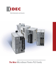
The New MicroSmart PLC Family
www.IDEC.com
“The features and adaptability of MicroSmart PLCs make them my first
choice for applications now and in
the future!“ – Project Manager
The Power to Control.
Anywhere. Anytime.
Power, Performance, Connectivity
Maximize efficiency and cut development time! MicroSmart PLCs combine advanced networking capabilities with
unparalleled power, performance and connectivity. Designed to meet all your communication requirements, now and
in the future, MicroSmart Pentra PLCs give you the flexibility to expand your system with as many as fifteen modules!
Our new Embedded Ethernet PLC with built-in Modbus TCP also lets you monitor status in real-time, receive email
alerts and customize your own web page.
Safety
All MicroSmart PLCs (FC4A and FC5A) meet the highest standards for safety including: cULus listed, CE compliant, as
well as certified for marine use by ABS (American Bureau of Shipping), DNV (Det Norskes Veritas), GL (Germanischer
Lloyd) and LR (Lloyd's Register of Shipping).*
*Note: The following products are pending approval for UL, ABS, DNV and Lloyd’s Registry
FC5A-D12*, FC4A-K4A1, FC4A-PM128, FC5A-F2M2, FC5A-F2MR2, FC5A-SIF2, FC5A-SIF4, FC5AC**R2D, FC5A-EXM*, FC4A-SX5ES*, FC4A-AS62M, and FC4A-N08A11.
2
Setting the standards for automation…again
The MicroSmart Pentra PLC Family: Everything you need in a controller
Embedded Ethernet Port
Email and text notifications
Modbus TCP, RTU and ASCII
USB programming port
Seven communication ports
NEW Advanced PID modules
User web page
NEW 4-pt. analog output module
3
www.IDEC.com
A CPU for every application
With three controller types to choose from, MicroSmart Pentra PLCs offer the features you need for your
applications. Built to allow you the flexibility to expand when you need to, MicroSmart Pentra PLCs are the
best way to get everything you need in just one controller.
Note: For a comparison of FC5A and FC4A functions, see CPU Highlights on pages 22 and 23.
Potentiometer
0-10V DC Analog Input
(8-bit resolution)
Power, Status, I/O
LED Indicators
Removable Terminal
Block
Optional HMI module
Optional Clock Cartridge
USB mini-B
Programming Port
Optional HMI base module
Optional
EEPROM cartridge
(up to 128KB)
• Optional RS232C adaptor
(8-pin mini DIN connector)
• Optional RS485 adaptor
(8-pin mini DIN or screw
terminal connector)
RJ-45 Ethernet Port
• Optional RS232C module
• Optional RS485 module
(mini-DIN or screw terminal type)
Power Terminal
Slim CPU with Ethernet Port
Modules snap together easily without the
need for additional tools.
4
The perfect design when you need Ethernet capability, this
slim CPU with embedded Ethernet port is available with
24V DC power and equipped with eight DC inputs and four
transistor outputs (sink or source). Up to seven functional
modules, including analog and communication modules
can be mounted on the right-hand expansion bus. Using an
expansion interface module, an additional eight discrete
expansion modules can be mounted.
Setting the Standards for Design
Potentiometer (x2)
0-10V DC Analog Input
(8-bit resolution)
Potentiometer
Optional HMI module
RS232C port
RS232C port
Optional Clock
Cartridge
• Optional RS232C adaptor
(8-pin mini DIN connector)
• Optional RS485 adaptor
(8-pin mini DIN or screw
terminal connector)
Power, Status, I/O
LED Indicators
Optional EEPROM
cartridge
Screw Terminal or MIL
connector termination
• Optional EEPROM cartridge
• Optional Clock Cartridge
Slim CPU
All-in-One CPU
If you don’t need Ethernet, but still want a high-performance
CPU, the MicroSmart Pentra slim CPU is your best choice!
Available with 24V DC power, this controller has all the
functionalities you need in 16 and 32 I/O configurations. Each
16 I/O CPU is equipped with eight DC inputs, two transistor outputs (sink or source) and six relay outputs, while the
32 I/O CPU is equipped with 16 DC inputs and 16 transistor
outputs (sink or source).
Available with 12V DC, 24V DC and 100-240V AC power, you
can choose from 10, 16 and 24 I/O configurations. The 10 I/O
CPU is equipped with six DC inputs and four relay outputs,
while the 16 I/O CPU is equipped with nine DC inputs and
seven relay outputs. The 24 I/O CPU is equipped with 14 DC
inputs and ten relay outputs. The 24 I/O CPU (24V DC and
100-240V AC models) can also be expanded with a maximum
of four functional or discreet expansion modules.
5
www.IDEC.com
Communicate with Modbus Protocol
Modbus is a communications protocol, which over the years
has become a standard in the automation industry. The main
reasons for the extensive use of Modbus over other communications protocols are because it is:
1. 2. 3. 6
Openly published and royalty-free
A relatively easy industrial network to deploy
Able to move raw bits or word data without placing many restrictions on vendors
Modbus is often used to connect a supervisory computer
with a remote terminal unit (RTU) in supervisory control
and data acquisition (SCADA) systems. All IDEC
MicroSmart Pentra PLCs support Modbus protocol.
Using intuitive WindLDR software, you can configure the
MicroSmart Pentra to be a Master or Slave device on a
Modbus network. All MicroSmart Pentra PLCs support
Modbus RTU/ASCII protocols and our CPU with embedded
Ethernet port also supports Modbus TCP protocol.
Setting the Standards for Connectivity
Modbus Connectivity with TCP, RTU and ASCII
Web Browser - Remote
Monitor & Control
WindLDR Software
Monitor & Update Program
SCADA
Supervisory Controls
TCP/IP
Modbus TCP
Server 255
Modbus TCP
Client
Ethernet
Modbus TCP
Server 3
Pentra with
Radio Modem
Modbus TCP
Server 2
Modbus TCP
Server 1
Modbus TCP
MicroSmart Pentra PLCs with embedded Ethernet port
support Modbus TCP Client (Master) or Server (Slave)
communications. When the MircroSmart Pentra is configured
as a client (master) on the Modbus TCP network, up to 3
connections can be established. Each connection can
communicate with up to 255 server (slave) devices. On top
of that, you can make connections to the PLC using WindLDR
software for program monitoring, upload or download. You
can also use a web browser for remote access to the PLC,
even though the Ethernet port is already configured for
Modbus TCP connections.
Operator
Interface
Pentra
Pentra
Modbus RTU and ASCII
For standard MicroSmart Pentra PLCs, up to 7 communication
ports can be configured as Modbus RTU and/or ASCII master
or slave. It is even possible to have one PLC act as a master
in one Modbus network, while at the same time acting as
a slave in another Modbus network! There is no restriction
on how the Modbus networks are set up with MicroSmart
Pentra PLCs.
VFD
Modbus RTU/ASCII
RS485
Operator
Interface
Temperature
Controller
Pentra with
Radio Modem
“Seamless communication between all
my devices is a big deal. And it doesn’t
get easier than with a Pentra controller!“
– System Integrator
7
www.IDEC.com
Built-in Ethernet for fast,
reliable connectivity
Ethernet is the fastest growing segment of industrial
networking, allowing reliable access-from-anywhere
capability and easy remote-data archiving. It makes
sense: you can’t always be in the same location as
your machinery, but with IDEC MicroSmart Pentra
PLCs, you don’t need to be. Now you can monitor
status in real-time, receive email alerts and customize
your own web pages.
MicroSmart Pentra PLC with embedded Ethernet
With an easy-to-configure, built-in Ethernet port, you
can set up your systems for remote access in no time.
Remote Access and Control
With this latest model, you can configure the MicroSmart Pentra PLC for remote
monitoring and control. Using WindLDR software, you can remotely monitor or update
the PLC programs without having to be near the PLC.
Web Server Functions
Using standard web browsers like Internet Explorer or Firefox, you can remotely log-in and
access web pages that are stored directly on the MicroSmart Pentra PLC. Up to 1 MB of
memory is dedicated for web page storage! Use the built-in web pages or create your own
using an HTML editor.
Ping Functions
A new PING instruction, available in the MicroSmart Pentra PLCs with embedded Ethernet,
allows the PLC to ping other PLCs or devices on a network to verify if that device is active
or offline. It’s a great way to make sure all your systems are working.
8
Setting the Standards for Connectivity
Instant Email and Text Alerts
Never have to worry that you will be out of touch with your
control system. MicroSmart Pentra PLCs have the ability
to send email or text messages to your inbox and mobile
phone. You can instantly be notified if any abnormal
conditions occur. Or simply have the PLC configure and
send daily operational status updates. Not only can static
information with up to 1,500 characters (1 byte per
character) be sent in one message, but data register values
can be incorporated as well.
A new EMAIL instruction is now available in WindLDR
software. You can program as many EMAIL instructions
as you prefer as long as you don’t exceed the programming memory capacity. A total of 255 email messages can
be configured in each PLC. Each email message can be
sent to multiple recipients. That means you can have as
many people receive the email as required! MicroSmart
Pentra PLCs also support email login authentication, which
requires each sender to be verified by a username and
password.
Any Network
Device (Server)
Touchscreen
(Client)
Maintenance
Communication
Server
Connections
Any Network
Device (Server)
Internet
Modbus TCP
Client Connections
WindSRV
(Client)
Up to 8
Connections
WindLDR
(Client)
Any Network
Device (Client)
Any Network
Device (Server)
Any Network
Device (Client)
Server Connections
Up to 14 Simultaneous Connections
Using Maintenance Communication Server connections, up to 3 Client devices, such as an operator interface,
WindLDR software and SCADA OPC server such as WindSRV (KepServerEx), can simultaneously communicate
with your MicroSmart Pentra PLC. Using Server Connections, an additional 8 connections can be established
and each connection can be defined as Maintenance, User Communication or Modbus TCP server protocol. On
top of that, another 3 connections can be configured as Modbus TCP client protocol, with a maximum of 255
requests. Each request can be for different slave devices with different IP addresses on the network.
9
www.IDEC.com
Customize critical data for
quick online monitoring
Using the MicroSmart Pentra PLC with embedded Ethernet,
you have the ability to design and create your own web
page. Using a standard web browser, such as Internet
Explorer or Firefox, critical information in the PLC can be accessed and controlled remotely over the web. Up to 1MB of
memory is reserved for web server functions.
With your web page, data is easy to access and read. Your
web page can display important parameters such as flow
rate, pressure, temperature, speed etc. of your system. These
parameters can then be remotely monitored and updated.
Need to change and update set points, no problem!
Using any standard HTML editor; design and create your
own web pages and then import these files to the WindLDR
software. WindLDR will download the HTML files to the
embedded Ethernet MicroSmart Pentra CPU. It’s that simple!
Design it the way you want.
“With MicroSmart Pentra, I can check on our assembly lines right from the office, no matter where they’re located. Makes my life a whole lot easier!” – Product Manager
10
Setting the Standards for Connectivity
Cellular modems let
you connect anywhere
If your system is located in a remote, unpopulated area where a
simple internet connection isn’t available, monitoring equipment
spread across a large geographic region can be difficult. Usually
someone must drive to each location to manually monitor critical
information, which is both time consuming and costly. So what
do you do if an internet connection isn’t available where your
system is installed? A GSM/CDMA wireless modem lets you
access your system remotely through mobile carriers in the
GSM/CDMA network.
MicroSmart Pentra PLCs have been installed in various
applications where they provide seamless communications
through a third party GSM/CDMA cellular modem and its
network. Data can then be streamed from the PLC to your
servers or central office. Critical information can be remotely
accessed 24/7, even in systems deployed in remote and
unpopulated areas where internet service is not accessible.
•
•
•
•
Cellular Modem
IDEC Operator Interface
Internet
Server
Reliable cellular connections
24/7 monitoring
Alarms and system status alerts
Remote updating for PLC programs
11
www.IDEC.com
Connect your devices by
expanding to 7 ports
Just imagine all the possibilities you will experience
with the flexibility of a powerful MicroSmart Pentra
Slim PLC. You can configure and seamlessly communicate with as many as 7 serial devices via RS232C
or RS485. MicroSmart Pentra PLCs are the only micro
PLC in the market to combine so much power and
flexibility in one controller.
Communicate to any device
With MicroSmart Pentra PLCs, you don’t have to
worry about limited communication capabilities. It
doesn’t matter if you’re just starting out or a current
user expanding your MicroSmart Pentra PLC, you
can rest assured that these communication modules
will provide reliable and seamless communication. If
RS485 modules are used for all six ports (one RS485
communication module and five SIF4 modules), up to
186 RS485 slave devices can be connected with
as high as a 115K baud rate available for fast
transmission.
Slave 31
Port 1
RS232C
Port 3
RS232C/RS485
Master Pentra PLC
Ether
net
Operator
Interface
col
oto
r
P
s
dbu
Mo
Temperature Controller
VFD (Variable Frequency Drive)
Sensing Device
12
Port 5
RS232C/RS485
VFD
Slave 2
Slave 1
Port 6
RS232C/
RS485
Port 2
RS232C/RS485
WindSRV SCADA Application
Data
link P
rotoc
ol
Port 4
RS232C/RS485
Port 7
RS232C/RS485
Temperature Controller
Multiple networks of Modbus protocols
IDEC MicroSmart PLCs can support Modbus
communication protocol and each of the seven
communication ports support Modbus protocol. You
can configure one port to talk Modbus RTU master,
another port for Modbus RTU slave, and more.
Network thousands of I/Os
Using IDEC Datalink and/or Modbus protocol, you
can configure tens of thousands of I/Os with one
MicroSmart Pentra PLC.
Setting the Standards for Performance
Boost the speed
of productivity
The success of your system might be dependent on a few
milliseconds. Many micro controllers lack the necessary
tools for accuracy at any speed, much less at the high speeds
modern applications require. MicroSmart PLCs have always
had the capability to operate high speed inputs and outputs,
but MicroSmart Pentra PLCs can go even faster, up to 100kHz
– and so can your productivity.
High-speed inputs
• Four high-speed inputs with a maximum
frequency of 100kHz
• Supports single/dual phase inputs for rotary encoders
• 32-bit counting range up to 4,294,967,295 pulses
• Integrated Functions
- Execute Interrupt Programs
- Frequency Measurement
- High Speed Counter Refresh
- Multi Stage Comparison
High-speed outputs
Configure as many as three high speed pulse outputs, up to
100kHz, and get the simple control you want for stepper or
servo motors.
13
www.IDEC.com
Connect up to 56 analog devices
1
2
3
Process controls play an important part in industrial
machines. Analog signals such as pressure transducers, float
switches, flow meters, valves, temperature, analog sensors
and more, need to be correctly analyzed and controlled.
MicroSmart Pentra PLCs offer a wide range of solutions,
including 0-10V DC, 4-20mA, resistance thermometer,
thermistor and thermocouple inputs, and -10 to 10V DC
and 4-20mA outputs. Analog modules are available in 12
or 16-bit resolution, providing a precise reading and fast
throughput.
4
5
6
7
Revolutionary universal input module
IDEC also offers a universal analog input module. This
4-pt universal analog input module can accept any of the
following types of analog signals: 4-20mA, 0-10V DC,
resistance thermometer and type J, K or T thermocouple!
Easy to configure and scale
Setting up analog modules in your PLC system should not
be a challenge. Using our analog setting macro instruction
in WindLDR software, you can easily set up and scale your
analog signals in no time at all.
Expand to 56 Analog I/O
7 analog I/O expansion modules can be configured on
MicroSmart Pentra PLCs. That’s a total of 56 analog
channels that you can utilize!
Part Number
I/O Points
Input
Output
Resolution
FC4a-j8c1
8 (8 inputs)
0-10 VDC, 4-20 mA
-
16-bit (0-50,000)
12-bit (0-4095)
FC4a-l03a1
3 (2 inputs, 1output)
0-10 VDC, 4-20 mA
FC4a-j2a1
2 (2 inputs)
-
FC4a-j4cn1
4 (4 inputs)
0-10 VDC, 4-20 mA,
RTD, Thermocouple
-
FC4a-l03ap1
3 (2 inputs, 1output)
RTD, Thermocouple
0-10 VDC, 4-20 mA
12-bit (0-4095)
FC4a-j8at1
8 (8 inputs)
Thermistor (NTC/PTC)
-
12-bit (0-4000)
-
FC4a-k4A1
4 (4 outputs)
0-10 VDC, 4-20 mA
12-bit (0-4095)
FC4a-k2c1
2 (2 outputs)
-10 to 10 VDC, 4-20 mA
16-bit (0-50,000)
FC4a-k1a1
1 (1 output)
0-10 VDC, 4-20 mA
12-bit (0-4095)
Choose from a wide range of available modules.
14
16-bit (0-50,000)
Modules are easy to configure using WindLDR software.
Setting the Standards for Performance
Advanced PID for precision control
PID (Proportional Integral Derivative) is the most commonly
used feedback control loop in industrial control systems. PID
calculates an error value as the difference between a measured process variable and a desired set point. The controller
then attempts to minimize the error by adjusting the process
control. With MicroSmart Pentra PLCs, PID implementation
can be deployed in two ways: integrated PID controls or a
dedicated Process Control module, which can be mounted
on the MicroSmart Pentra expansion bus.
Integrated PID Controls
Using built-in PID functions in the MicroSmart Pentra PLCs,
and in conjunction with analog I/O expansion modules, a
maximum of 56 PID loops can be programmed. A PID Macro
instruction in WindLDR software is also available to guide
you through the process of setting up and tuning the P, I
and D parameters. You can also select from various control
modes including Auto-tuning, Advanced Auto-tuning or
Manual.
Advanced PID Module
A dedicated PID module is available for extreme stability
and complex applications. This particular module has more
functionalities than you will find in any other controller on
the market. Independent of CPU scan time, the PID Control
module does the work, reducing PLC scan time without
taking up PLC memory space.
P
Setpoint
+
Error
I
K p e(t)
t
Process
Ki ∫
Output
0
–
D
Kd
de(t)
dt
PID Module Highlights:
• Precise, stable and accurate PID control with less than a 0.2% error
• Available in two models:
– Built-in 2 analog inputs, 2 x 4-20mA/
0-10V DC outputs
– Built-in 2 analog inputs, 2 x relay
outputs
• Each input individually configured to
accept different signal types
• Up to seven modules can be mounted on
the MicroSmart Pentra
• Maximum 14 PID loops with auto-tuning
• 14-bit resolution
• ARW (anti-reset windup)
• Accepts many different input types
including:
– Type K, J, R, S, B, E, T, C, PL-II and N
thermocouples
– Resistance thermometer
– 0-20mA and 4-20mA
– 0-1V, 0-5V, 1-5V, and 0-10V DC
• Numerous control methods including:
– Cascade
– External set point
– Heating and cooling control action
– Difference input control
15
www.IDEC.com
Solar ready
12V DC models
With abundant features and unparalleled performance,
12V DC MicroSmart Pentra PLCs are the perfect choice for
solar applications, including traffic signs, light controls, road
sign controls, remote pumping and injection systems for oil
and gas industries, remote water pumping stations and solar
tracking systems. For mobile applications, these PLCs can
be employed in utility vehicles such as cement mixers, lift
controls for the handicapped, lighting and even designation
signs for vans and buses.
“12V DC MicroSmart controllers
are compact enough to fit in a tight
space, while providing the controls
I need.” – Engineer
16
Setting the Standards for Performance
Meets rigorous
maritime standards
FC5A/FC4A series PLCs are one of the few PLCs in the market
approved for maritime applications. Our PLCs are widely used
in both marine and offshore applications.
We are dedicated to ensuring the safety of life and property
at sea. Our FC5A/FC4A series PLCs are trusted and approved
by leading maritime classification agencies, such as ABS
(American Bureau of Shipping), DNV (Det Norskes Veritas), GL
(Germanischer Lloyd) and LR (Lloyd's Register of Shipping).
MicroSmart Pentra PLCs are the perfect solution for all your
maritime applications! The MicroSmart Pentra PLC combines
power and ease-of-use to give you a simple and flexible
programming concept that can be tailored to your specific
application.
Note: The following part numbers are pending approval from ABS,
DNV and Llyod’s FC5A-D12* FC4A-K4A1, FC5A-F2M2, FC5A-F2MR2,
FC5A-SIF2, FC5A-SIF4, FC5A-C**R2D, FC5A-EXM*, FC4A-SX5ES*,
FC4A-AS62M, FC4A-N08A11.
17
www.IDEC.com
A fast and flawless OPC solution
Want your control systems centralized, easy-to-manage and
able to take advantage of the components you already have?
WindSRV, also known as KEPServerEX, is an OPC server
that provides direct connectivity between client applications
and IDEC MicroSmart Pentra PLCs. It’s a true plug-and-play
OPC Server with effortless data management, acquisition,
monitoring and control. Plus it supports complete addressing,
including 32-bit data and floating point data.
Industrial strength, easy to use OPC Server
The intuitive interface makes connecting IDEC MicroSmart
Pentra PLCs so easy that within minutes you can be providing
data to your application. KEPServerEX maximizes the promise
of OPC through the use of a single server interface, ensuring:
• Shorter product learning curves
• Reduced system training and maintenance costs
• Improved network reliability
Control at your fingertips
A maximum of 100 MicroSmart/MicroSmart Pentra PLCs can
be connected. Imagine having the ability to centrally monitor
and control your whole plant, at your fingertips.
18
Quick Client
Using Quick Client, you can access all data available to the server
application, including System, Diagnostic- and User-defined tags.
After you’ve created a simple KEPServerEX project, auto launch
Quick Client from the server toolbar to test your device connection.
Setting the Standards for Performance
Fastest micro PLC in its class
Expanded Memory
You won’t run out of program memory space with our
MicroSmart Pentra PLCs. The slim type CPU supports up to
62K bytes (10,400 steps) of programming memory. And if
that’s still not enough for your applications, a new optional
memory cartridge for the embedded Ethernet PLC is now
available with 128K bytes (21,300 ladder steps).
MicroSmart Pentra is also equipped with:
• 48,000 Data Registers
• 2,048 Internal Relays
• 256 Timers
• 256 Counters
Fast Processing Speed
MicroSmart Pentra Slim CPU is the fastest PLC in its class.
In fact, the overall processing speed of our new Logic Engine
CPU is 16 times faster than our competitor’s average controller for simple instruction execution, and more than 14 times
faster when executing advanced instruction sets.
USB maintenance port
The new MicroSmart Pentra PLC with an embedded Ethernet
PLC port also has an embedded mini-B USB port for maintenance. You can now easily connect your PC to this PLC using
a standard USB cable.
FREE Upgradeable Firmware
MicroSmart Pentra PLCs can keep up with your always
expanding applications. This is thanks to field upgradeable firmware that allows you to upgrade and download
system firmware as needed. And you never have to worry
new features and functions won’t be compatible with your
MicroSmart Pentra PLC. The newest firmware is always
available when you download our most recent version of
Automation Organizer suite. Upgrades are always free to
our users.
Comments and Tags download
With up to 128K bytes of programming memory, you are
free to load as much information into the PLC as you like.
All comments and tag identification can be downloaded and
will reside in the PLC for better understanding and clarification. No other micro PLC can offer this much programming
memory and more importantly, flexibility.
MicroSmart Pentra Slim CPU Speed Comparison (µsecs)
0.9
LOD instructions
0.056
2.4
MOV instructions
0.167
0
0.5
1
IDEC MicroSmart Pentra
1.5
2
2.5
Leading Competitor Controller
19
www.IDEC.com
Automation Organizer lets you
design, debug and document
Automation Organizer (AO) is a powerful software suite
containing PLC programming software (WindLDR), operator
interface configuration software (WindO/I-NV2) and system
configuration software (WindCFG). AO boasts a completely
new graphic user interface and redesigned menu icons.
AO is a one-stop automation software package for IDEC
MicroSmart Pentra PLCs and IDEC operator interfaces, and is
compatible with Windows XP, Vista (32 bit) and Windows 7
(32 and 64-bit).
FREE Upgrades
The Automation Organizer suite comes with free lifetime
upgrades. Once you make the initial purchase, upgrades are
absolutely free.
20
“ AO just makes sense. It’s the little
things like a common tag name database for both my PLC and HMI controls.” - Engineer
Setting the Standards for Performance
All IDEC MicroSmart Pentra PLCs are programmable with WindLDR
ladder logic software. This icon-driven programming tool combines logic
and intuition with an incredibly easy-to-use interface to allow you to
take advantage of MicroSmart features. Even without ladder program
experience, you can use the built-in editors, shortcuts and debuggers to
configure programs. WindLDR is an excellent, long-term investment for
your control solutions.
Simulation Mode
WindLDR allows you to simulate ladder programs with built-in
Simulation mode. You can easily test and verify functionality of your
ladder program without actual hardware.
Online Editing
Shutting down your PLC for minor changes can be a major hassle, so
WindLDR allows you to edit and download programs without interrupting PLC operation. You can write new values to counters, timers
and registers at any time without switching between editor mode
(for programming) and monitor mode.
Firmware Download
With WindLDR version 6.4 or later, you have the option to upgrade
or downgrade your CPU system program. It’s as simple as clicking
on the checkbox in the Download dialog box. Now you can easily
update your PLC system firmware with the click of a button.
WindO/I-NV2 software is the programming tool available for all IDEC
operator interfaces. It is used to create projects or programs that can
display information from a PLC, process status, or can be used to input
data with virtual switches or keypads to make changes to a process. The
objects are extremely easy to configure with the help of step-by-step
navigation. It lets you quickly create colorful graphical screens in no
time using drop-down menus and intuitive drag and drop functionality
for the objects. A workspace is available to help you organize and
manage projects, objects and screens.
WindCFG is a system layout and configuration tool for IDEC PLCs and
operator interfaces. Using WindCFG, you can create a visual layout
of the system design and basic configuration of your PLC and operator
interfaces.
21
www.IDEC.com
CPU Highlights
No matter your application, FC5A and FC4A have the features you need!
CPU Series
CPU Type
FC5A
Slim Type
CPU I/O size
Inputs
Outputs
Relay
Transistor
Max. I/Os
32 I/Os
16 I/Os
16
8
8
-
6
-
16
2
4
512 *1
496 *1
492 *1
Program Capacity
Instruction
Excecuting
Time
Advanced Instruction
Pulse Output
(Trapezoidal Control)
10 I/Os
14
9
6
10
7
4
-
-
-
16
10
27KB
13.8KB
88 *2
12V DC
24
54KB
LOD: 0.7 us (=micro sec.)
MOV: 0.167 to 0.278 us (=micro sec.)
MOV: 33 us (=micro sec.)
100kHz single/ two phase-selectable: 2 points
100kHz Single-phase: 2 points
100kHz (3-axis
simultaneous
control): 2 points
100kHz: (2-axis
simultaneous
control): 2
points
50kHz single/ two phase-selectable: 1 point
5kHz Single-phase: 3 points
100kHz (3-axis
simultaneous
control): 2 points
-
Combination with Analog
module
Possible Max. 56ch
Possible Max. 28ch
PID Module
Possible Max. 14ch
Possible Max. 8ch
-
-
-
1ch
2ch
2ch
1ch
1ch
2 ports
2 ports
Max. 2 modules
Max. 2
modules
-
-
-
-
Timer Interrupt Functions
Maximum Ports
Comminication Function Expandability
16 I/Os10 I/Os
24V DC type AC type
127.8KB
Built-in Analog Input (0-10V DC)
Possible
7 ports
8 ports
-
1 port
Built in CPU
-
-
1 port
FC4A Web Server Unit
Built in CPU
RS232C
Max. 7 modules
1 port
Max. 6 modules
1 port
5 ports
2 ports
-
Max. 5 modules
Max. 2
modules
-
1 port
-
1pce
Communication Module
1 module
-
Max. 5 modules
Max. 3 modules
-
Communication Adapter
-
1pce
Communication Module
1 module
-
Expansion RS485 Comm.
Module
Max. 5 modules
-
-
Communication Adapter
Expansion RS232C Comm.
Module
RS485
-
1ch
-
Ethernet
-
Possible
USB mini-B Built in CPU
Modbus Function
Option Module Combination
24 I/Os
LOD: 0.056 us (=micro sec.)
Analog Potentiometeter
Max. 3 modules
Master/slave function (standard feature)
-
Master/slave function (standard feature)
AS-Interface Master Module
Max. 2 modules
Max. 2 modules
-
-
-
Analog I/O Module
Max. 7 modules
Max. 4 modules
-
-
-
-
-
-
-
Analog I/O Module & AS-Interface
Master Module
Possible
-
Analog I/O Module & Expansion RS232C
or RS485 Communication Module
Possible
-
PID Module
Max. 7 modules
Max. 4 modules
-
PID Module & AS-Interface Master
Module
Possible
-
PID Module & Expansion RS232C or RS485
Communication Module
Possible
-
Analog Module & PID Module
Possible
AS-Interface Master Module & Expansion
RS232C or RS485 Communication Module
Possible
Expanshion Interface Module
Possible
-
Web Server Module
Possible
Possible
Width (mm)
Power Voltage
*1. When using expansion I/O modules and expansion interface modules.
*2. When using expansion I/O modules.
22
12 I/Os
62.4KB
Basic Instruction
High-speed Counter Max. counting frequency
PID Control
All-in-One Type
Web Server CPU Module
47.5
24V DC
Possible
-
95.0
80.0
FC5A-C**R2 (AC type): 100V to 240V AC (50/60 Hz)
FC5A-C**R2C (24V DC type): 24V DC
FC5A-C**R2D (12V DC Type): 12V DC
Setting the Standards for Design
CPU Series
CPU Type
FC4A
Slim Type
CPU I/O size
40 I/Os
Inputs
Outputs
Relay
Transistor
Max. I/Os
20 I/Os
12
14
9
6
6
-
10
7
4
16
10
15KB
4.8KB
16
2
8
-
264 *2
244 *2
148 *2
88 *2
27KB
27KB
MOV: 46 us (=micro sec.)
MOV: 46 us (=micro sec.)
20kHz single/ two phase-selectable: 1 point
5kHz Single-phase: 3 points
20kHz(1 or 2-axis control): 2 points
Combination with Analog
module
-
Possible
Max. 56ch
PID Module
Built-in Analog Input (0-10V DC)
Possible
Max. 28ch
-
-
-
-
-
-
1ch
2ch
1ch
1ch
1ch
Possible
Possible
Maximum Ports
Comminication Function Expandability
LOD: 1 us (=micro sec.)
20kHz single/ two phase-selectable: 2 points
5kHz Single-phase: 2 points
Analog Potentiometeter
-
-
2 ports
2 ports
1 port
USB mini-B Built in CPU
-
-
Built in CPU
-
-
Ethernet
FC4A Web Server Unit
Max. 2 modules
Built in CPU
RS232C
RS485
Max. 2 modules
1 module
1 port
1 port
Communication Adapter
-
1pce
Communication Module
1 module
-
Expansion RS232C Comm.
Module
-
-
Communication Adapter
-
1pce
Communication Module
1 module
-
Expansion RS485 Comm.
Module
-
-
Modbus Function
AS-Interface Master Module
1 module
Analog I/O Module
Analog I/O Module & AS-Interface
Master Module
Option Module Combination
-
LOD: 1 us (=micro sec.)
Advanced Instruction
Timer Interrupt Functions
-
Max. 7 modules
Possible
Max. 4 modules
-
-
-
Analog I/O Module & Expansion RS232C
or RS485 Communication Module
-
-
PID Module
-
-
PID Module & AS-Interface Master
Module
-
-
PID Module & Expansion RS232C or RS485
Communication Module
-
-
Analog Module & PID Module
-
-
AS-Interface Master Module & Expansion
RS232C or RS485 Communication Module
-
-
Expanshion Interface Module
-
-
Possible
Possible
Web Server Module
Width (mm)
Power Voltage
10 I/Os
12
31.2KB
Pulse Output
(Trapezoidal Control)
16 I/Os
-
Basic Instruction
High-speed Counter Max. counting frequency
PID Control
24 I/Os
24
Program Capacity
Instruction
Excecuting
Time
All-in-One Type
47.5
35.4
24V DC
95.0
80.0
80.0
FC4A-C**R2(AC type): 100V to 240V AC (50/60 Hz)
FC4A-C**R2C(DC type): 24V DC
*2. When using expansion I/O modules.
23
www.IDEC.com
MicroSmart PLC Specifications and Technical Data
High-performance quality programmable logic controller with world-class processing speed. Compact body packed with outstanding
features. New slim type CPU module available with web server function, ideal for remote control. (FC5A-D12*1E)
••New FC5A slim type modules available with web server function,
send email function, n:n communication by Modbus communication,
PING function. Supports user web page. (FC5A-D12*1E)
••Equipped with a USB port (mini-B) and Ethernet port for easy
maintenance, remote control and monitoring. (FC5A-D12*1E)
••World-class processing speed.
Logic Engine performance:
- Basic instruction LOD 0.056 µs
- Advanced instruction MOV 0.167 µs (FC5A slim type only)
••Equipped with Modbus ASCII/RTU master/slave function (FC5A).
••FC5A slim type expandable up to 512 I/O points (when expansion
interface modules are used).
••Full line up of analog modules including 4-point analog output module.
••FC5A PID module with high accuracy and high functionality available.
MicroSmart
••FC5A CPU Modules
Type
Slim
High-speed Counter
Pulse Output
••High-speed counter
Maximum input
frequency: 100 kHz
••Pulse output
Maximum output
frequency: 100 kHz
Power
Input Type
Output Type
Relay Output 2A
240V AC, 2A
30V DC, 2A
24V DC
24V DC
(Sink/Source)
High-speed
Transistor Output
Sink Output 0.3A
Source Output
0.3A
Transistor Sink Output 0.3A
Transistor Source Output 0.3A
Transistor Sink Output 0.3A
Transistor Source Output 0.3A
12V DC
All-in-One
••High-speed counter
Maximum input
frequency: 50 kHz
100V to
240V AC
(50/60 Hz)
Interface
Port 1 (RS232C)
Relay Output 2A
240V AC, 2A
30V DC, 2A
—
8/8 points (Note)
496 points max.
Type No.
FC5A-D16RK1
FC5A-D16RS1
16/16 points
512 points max.
FC5A-D32K3
FC5A-D32S3
Port 1
(USB mini-B port)
Ethernet port
8/4 points
492 points max.
FC5A-D12K1E
Port 1 (RS232C)
6/4 points
9/7 points
14/10 points
6/4 points
9/7 points
14/10 points
88 points max.
6/4 points
9/7 points
14/10 points
88 points max.
FC5A-C10R2D
FC5A-C16R2D
FC5A-C24R2D
FC5A-C10R2
FC5A-C16R2
12V DC
(Sink/Source)
24V DC
(Sink/Source)
I/O Points
24V DC
FC5A-D12S1E
FC5A-C24R2
FC5A-C10R2C
FC5A-C16R2C
FC5A-C24R2C
Note: Two points are transistor output and six points are relay outputs.
••FC4A CPU Modules
Type
Slim
All-in-One
High-speed counter
Pulse Output
••High-speed counter
Maximum input frequency: 20 kHz
••Pulse output
Maximum output frequency: 20 kHz
••High-speed counter
Maximum input frequency: 20 kHz
Power
24V DC
100V to
240V AC
(50/60 Hz)
Input Type
24V DC
(Sink/Source)
24V DC
(Sink/Source)
24V DC
Note: Two points are transistor output and six points are relay outputs.
24
High-speed
Transistor Output
Transistor Sink Output 0.3A
Transistor Source Output 0.3A
Sink Output 0.3A
Relay Output 2A
240V AC, 2A
Source Output 0.3A
30V DC, 2A
Transistor Sink Output 0.3A
Transistor Source Output 0.3A
Output Type
Relay Output 2A
240V AC, 2A
30V DC, 2A
—
I/O Points
12/8 points
148 points max.
12/8 points (Note)
244 points max.
24/16 points
264 points max.
6/4 points
9/7 points
14/10 points
88 points max.
6/4 points
9/7 points
14/10 points
88 points max.
Type No.
FC4A-D20K3
FC4A-D20S3
FC4A-D20RK1
FC4A-D20RS1
FC4A-D40K3
FC4A-D40S3
FC4A-C10R2
FC4A-C16R2
FC4A-C24R2
FC4A-C10R2C
FC4A-C16RC2
FC4A-C24R2C
Setting the Standards for Design
••Input Modules
Input Type
••Output Modules
Input Points
8 points
24V DC
(Sink/Source)
16 points
16 points
32 points
100 to 120V AC
(50/60Hz)
8 points
Terminal
Type No.
FC4A-N08B1
Removable Terminal Block
FC4A-N16B1
FC4A-N16B3
MIL Connector
FC4A-N32B3
Removable Terminal Block
FC4A-N08A11
Output Type
Output Points
Terminal
8 points
Relay Output
240V AC/30V DC
16 points
Transistor Sink Output 0.3A
8 points
Transistor Source Output 0.3A
Transistor Sink Output 0.1A
Removable
Terminal Block
16 points
Transistor Source Output 0.1A
MIL Connector
Transistor Sink Output 0.1A
32 points
Transistor Source Output 0.1A
Type No.
FC4A-R081
FC4A-R161
FC4A-T08K1
FC4A-T08S1
FC4A-T16K3
FC4A-T16S3
FC4A-T32K3
FC4A-T32S3
••Mixed I/O Modules
Input Type
Output Type
24V DC
(Sink/Source)
Relay Output
240V DC/30V DC, 2A
I/O Points
8 (4 in/4 out)
24 (16 in/8 out)
Input Type
Output Type
Terminal
Removable Terminal Block
Non-removable Terminal Block
Type No.
FC4A-M08BR1
FC4A-M24BR2
••Analog I/O Modules
Name
Voltage (0 to 10V DC)
Current (4 to 20mA)
Thermocouple
Resistance Thermometer
Voltage (0 to 10V DC)
Current (4 to 20mA)
Voltage (0 to 10V DC)
Current (4 to 20mA)
Thermocouple
Resistance Thermometer
Voltage (0 to 10V DC)
Current (4 to 20mA)
Analog I/O Module
Analog Input Module
Voltage (0 to 10V DC)
Current (4 to 20mA)
Terminal
Type No.
FC4A-L03A1
2 inputs
1 output
FC4A-L03AP1
2 inputs
FC4A-J2A1
4 inputs
FC4A-J4CN1
–
8 inputs
Thermistor (NTC, PTC)
Analog Output Module
I/O Points
Voltage (–10 to +10V DC)
Current (4 to 20mA)
Voltage (0 to 10V DC)
Current (4 to 20mA)
Voltage (-10 to 10V DC)
Current (4 to 20mA)
–
Removal Terminal Block
FC4A-J8C1
8 intputs
FC4A-J8AT1
2 outputs
FC4A-K2C1
1 output
FC4A-K1A1
4 outputs
FC4A-K4A1
••Expansion RS232C Communication Module
••PID Modules
Name
Relay Output Type × 2ch
Voltage / Current Output Type × 2ch
User’s Manual
Terminal
Non-removable
Terminal Block
Type No.
FC5A-F2MR2
FC5A-F2M2
FC9Y-B1283
Terminal
AS-interface Master Module
Type No.
Removable Terminal Block
FC4A-AS62M
Type No.
Type No.
FC5A-SIF4
RS485, 1 Port
••Communication Modules (For Slim CPU)
RS485 Communication Module
FC4A-SX5ES1E
FC4A-KC3C
FC9Y-B919
Mini DIN Connector Type
Mini DIN Connector Type
Terminal Block Type
Type No.
FC4A-HPC1
FC4A-HPC2
FC4A-HPC3
••Programming Software
Name
••Expansion Interface Modules
Name
Expansion Interface Master Module
Expansion Interface Slave Module
Expansion Interface Module
Expansion Interface Cable (1m)
••Expansion RS485 Communication Module
Name
RS232C Communication Module
••Web Server Unit
Name
Web Server Unit
Web Server Cable (10 cm)
User’s Manual
Type No.
FC5A-SIF2
Type
••AS-Interface Master Modules
Name
Type
RS232C, 1 Port
Type No.
FC5A-EXM1M
FC5A-EXM1S
FC5A-EXM2
FC5A-KX1C
Type No.
Application Software Automation Organizer
WindLDR V.6 or higher
SW1A-W1C
Programming and Monitoring Software
WindLDR Ver. 5.*
FC9Y-LP2CDW
••HMI Module
HMI Module
HMI Base Module
Name
For displaying and changing required
operands
For mounting HMI module with slim type CPU
module
Type No.
FC4A-PH1
FC4A-HPH1
25
www.IDEC.com
••Option
RS232C Communication Adapter
RS485 Communication Adapter
RS485 Communication Adapter
Clock Cartridge
Name
Mini DIN Connector
Mini DIN Connector
Terminal Block
Memory Cartridge
32 KB
64 KB
128 KB
RS232C/RS485 Converter
AC Adapter
26-position Connector Socket
20-position Connector Socket
10-position Terminal Block
11-position Terminal Block
MIL connector for slim type CPU modules (package quantity 2)
MIL connector for I/O modules (package quantity 2)
For I/O modules (package quantity 2)
For slim CPU modules FC5A-D16R*1 (package quantity 2)
For slim CPU modules FC4A-D20R*1 (package quantity 2)
For slim CPU modules FC5A-D16RK1/FC4A-D20RK1 (package quantity 2)
For slim CPU modules FC5A-D16RS1/FC4A-D20RS1 (package quantity 2)
16-position Terminal Block
For slim CPU modules FC5A-D12K1E (package quantity 2)
For slim CPU modules FC5A-D12S1E (package quantity 2)
Analog Voltage Input Cable (1m long) (package quantity 2)
Direct Mounting Strip (package quantity 5)
Aluminium (package quantity 10)
35-mm-wide DIN Rail (1m long)
Steel (package quantity 10)
End Clip (package quantity 10)
Computer Link Cable 4C (3m long)
Modem Cable 1C (3m long)
User Communication Cable 1C (2.4m long)
USB Maintenance Cable (2m long, USB-mini B)
Panel Mount Extension Cable (1m long, USB-mini B)
O/I Communication Cable 1C (5m long) for connecting HG1F to MicroSmart port 1 and 2 (RS232C)
O/I Communication Cable (3m long) for connecting HG1F to MicroSmart port 2 (RS232C)
O/I Communication Cable 2C (5m long) for connecting HG2F/3F/4F to MicroSmart port 1 and 2 (RS232C)
O/I Communication Cable (5m long) for connecting HG2F/3F/4F to MicroSmart port 2 (RS232C)
O/I Communication Cable 1C (2.4m long) for connecting HG2G/3G to MicroSmart port 1 and 2 (RS232C)
O/I Communication Cable 1C (5m long) for connecting HG2G/3G to MicroSmart port 1 and 2 (RS232C)
O/I Communication Cable 1C (5m long) for connecting HG3G D-sub pin to MicroSmart port 1 and 2 (RS232C)
0.5m
1m
Shielded
2m
3m
20-wire
0.5m
1m
Non-shielded
2m
3m
I/O
Terminal Cable
0.5m
1m
Shielded
2m
3m
26-wire
0.5m
1m
Non-shielded
2m
3m
Basic & Advanced
User’s Manual *
MicroSmart User’s Manual (FC5A)
Web Server CPU Module
(English)
Automation Organizer
PID Module
13-position Terminal Block
Type No.
FC4A-PC1
FC4A-PC2
FC4A-PC3
FC4A-PT1
FC4A-PM32
FC4A-PM64
FC4A-PM128
FC2A-MD1
PFA-1A31
FC4A-PMC26PN02
FC4A-PMC20PN02
FC4A-PMT10PN02
FC4A-PMT11PN02
FC5A-PMT13PN02
FC4A-PMT13PN02
FC4A-PMTK16PN02
FC4A-PMTS16PN02
FC5A-PMTK16EPN02
FC5A-PMTS16EPN02
FC4A-PMAC2PN02
FC4A-PSP1PN05
BAA1000PN10
BAP1000PN10
BNL6PN10
FC2A-KC4C
FC2A-KM1C
FC2A-KP1C
HG9Z-XCM42
HG9Z-XCE21
FC4A-KC1C
HG9Z-XC183
FC4A-KC2C
HG9Z-3C125
FC2A-KP1C
HG9Z-XC275
HG9Z-XC295
FC9Z-H050A20
FC9Z-H100A20
FC9Z-H200A20
FC9Z-H300A20
FC9Z-H050B20
FC9Z-H100B20
FC9Z-H200B20
FC9Z-H300B20
FC9Z-H050A26
FC9Z-H100A26
FC9Z-H200A26
FC9Z-H300A26
FC9Z-H050B26
FC9Z-H100B26
FC9Z-H200B26
FC9Z-H300B26
FC9Y-B1138
FC9Y-B1278
FC9Y-B1283
*MicroSmart User’s manual and manuals below (applicable to Automation Organizer) can be downloaded from http://www.idec.com/japan/ao/
••FC5A MicroSmart User’s Manual Basic/Advanced/Web Server CPU module/PID module: Japanese, English, Chinese, German
••FC4A MicroSmart User’s Manual: Japanese, English, Chinese, German, Spanish
••FC5A MicroSmart User’s Manual (applicable to WindLDR V.5): Japanese, English, Chinese, German, Spanish
••FC4A MicroSmart User’s Manual (applicable to WindLDR V.5): Japanese, English, Chinese, German, Spanish
26
Setting the Standards for Design
Specifications (CPU Modules)
••Slim Type
Type No.
Rated Power Voltage
Allowable Voltage Range
Maximum Input Current
Maximum Power Consumption
Allowable Momentary
Power Interruption
Dielectric Strength
Insulation Resistance
Noise Resistance
Inrush Current
Power Supply Wire
Operating Temperature
Storage Temperature
Relative Humidity
Altitude
Pollution Degree
Corrosion Immunity
Degree of Protection
Grounding Wire
Vibration Resistance
Shock Resistance
Weight
FC5A-D12K1E
FC5A-D16RK1
FC5A-D12S1E
FC5A-D16RS1
24V DC
20.4 to 26.4V DC (including ripple)
700 mA (26.4V DC) *1
19W (26.4V DC) *1
FC5A-D32K3
FC5A-D32S3
FC4A-D20K3
FC4A-D20S3
560 mA (26.4V DC) *1
14W (26.4V DC) *1
FC4A-D20RK1
FC4A-D20RS1
FC4A-D40K3
FC4A-D40S3
700 mA (26.4V DC) *1
17W (26.4V DC) *1
10 ms (at 24V DC)
terminals: 500V AC, 1 minute
Between power and
terminals: 500V AC, 1 minute
Between I/O and
terminals: 10 MΩ minimum (500V DC megger)
Between power and
terminals: 10 MΩ minimum (500V DC megger)
Between I/O and
DC power terminals: 1.0 kV, 50 ns to 1 µs
I/O terminals (coupling clamp): 1.5 kV, 50 ns to 1 µs
50A maximum (24V DC)
UL1015, AWG22, UL1007 AWG18
0 to 55°C
–25 to +70°C (no freezing)
Level RH1 (IEC61131-2), 10 to 95% (no condensation)
Operation: 0 to 2,000m, Transport: 0 to 3,000m
2 (IEC60664-1)
Free from corrosive gases
IP20 (IEC60529)
UL1015, AWG22, UL1007, AWG18
When mounted on a DIN rail or panel surface:
5 to 8.4 Hz amplitude 3.5 mm, 8.4 to 150 Hz acceleration 9.8 m/s2 (1G),
2 hours per axis on each of three mutually perpendicular axes (IEC61131-2)
147 m/s2 (15G), 11 ms duration, 3 shocks per axis on three mutually perpendicular axes (IEC61131-2)
200g
230g
190g
140g
185g
180g
*1: CPU module + 7 I/O modules
••All-in-One Type
Type No.
Rated Power Voltage
Allowable Voltage Range
Rated Power Frequency
Maximum Input Current
Maximum
Power
Consumption
AC Power
DC Power
Allowable Momentary
Power Interruption
Dielectric Strength
Insulation Resistance
Noise Resistance
Inrush Current
Power Supply Wire
Operating Temperature
Storage Temperature
Relative Humidity
Altitude
Pollution Degree
Corrosion Immunity
Degree of Protection
Ground
Grounding Wire
Vibration Resistance
Shock Resistance
Weight
FC5A-C10R2
FC5A-C16R2
FC5A-C24R2
FC5A-C10R2C
FC5A-C16R2C
FC5A-C24R2C
FC5A-C10R2D
FC5A-C16R2D
FC5A-C24R2D
AC power type: 100 to 240V AC, DC power type: 24V DC, 12V DC
FC4A-C10R2
FC4A-C10R2C
FC4A-C16R2
FC4A-C16R2C
AC power type: 85 to 264V AC, 24V DC power type: 20.4 to 28.8V DC (including ripple), 12V DC type: 10.2 to 18.0V DC
AC power type: 50/60 Hz (47 to 63 Hz)
250 mA (85V AC)
300 mA (85V AC)
450 mA (85V AC) *2
250 mA (85V AC)
300 mA (85V AC)
160 mA (24V DC)
190 mA (24V DC)
360 mA (24V DC) *3
160 mA (24V DC)
190 mA (24V DC)
FC5A-C10R2/FC4A-C10R2: 30VA (264V AC), 20VA (100V AC) *4
FC5A-C16R2/FC4A-C16R2: 31VA (264 V AC), 22VA (100V AC ) *4
FC5A-C24R2/FC4A-C24R2: 40VA (264V AC), 33VA (100V AC) *2
FC5A-C10R2C/FC4A-C10R2C: 3.9W (24V DC) *5
FC5A-C10R2D: 2.8W (12V DC) *5
FC5A-C16R2C/FC4A-C16R2C: 4.6W (24V DC) *5
FC5A-C16R2D: 3.4W (12V DC) *5
FC5A-C24R2C/FC4A-C24R2C: 8.7W (24V DC) *3
FC5A-C24R2D: 4.2W (12V DC) *5
FC4A-C24R2
FC4A-C24R2C
450 mA (85V AC) *2
360 mA (24V DC) *3
10 ms (rated power voltage)
or
terminals: 1,500V AC, 1 minute
Between power and
or
terminals: 1,500V AC, 1 minute
Between I/O and
or
terminals: 10 MΩ minimum (500V DC megger)
Between power and
or
terminals: 10 MΩ minimum (500V DC megger)
Between I/O and
AC power terminals: 1.5 kV, 50 ns to 1 µs
DC power terminals: 1.0 kV, 50 ns to 1 µs
I/O terminals (coupling clamp): 1.5 kV, 50 ns to 1 µs
FC5A-C10R2/FC5A-C10R2C/FC5A-C16R2/
FC5A-C24R2/
FC5A-C16R2C: 35A
FC5A-C24R2C: 40A
35A
FC5A-C10R2D/FC5A-C16R2D: 20A
FC5A-C24R2D: 20A
UL1015 AWG22, UL1007 AWG18
0 to 55°C
–25 to +70°C (no freezing)
Level RH1 (IEC61131-2), 10 to 95% (no condensation)
Operation: 0 to 2,000m, Transport: 0 to 3,000m
2 (IEC60664-1)
Free from corrosive gases
IP20 (IEC60529)
Ground resistance 100Ω (max.)
UL1007, AWG16
When mounted on a DIN rail or panel surface:
5 to 8.4 Hz amplitude 3.5 mm, 8.4 to 150 Hz acceleration 9.8 m/s2 (1G),
2 hours per axis on each of three mutually perpendicular axes (IEC61131-2)
147 m/s2 (15G), 11 ms duration, 3 shocks per axis on three mutually perpendicular axes (IEC61131-2)
AC type: 230g
AC type: 250g
AC type: 305g
AC type: 230g
AC type: 250g
DC type: 240g
DC type: 260g
DC type: 310g
DC type: 240g
DC type: 260g
*2: CPU module (including 250 mA sensor power) + 4 I/O modules
*3: CPU module + 4 I/O modules
*4: CPU module (including 250 mA sensor power)
40A
AC type: 305g
DC type: 310g
*5: CPU module
27
www.IDEC.com
••Slim Type Function Specifications
Type No.
Control System
Instruction Words
Program Capacity *1
User Program Storage
Processing Basic Instruction
Time
END Processing *3
Expandable I/O Modules
I/O
Points
Input
Output
RAM Backup
Internal Relay
Shift Register
Data Register
Expansion Data Register
Counter
Timer (1-sec, 100-ms, 10-ms, 1-ms)
Backup Data
Backup Duration
Battery
Charging Time
Battery Life
Replaceability
Self-diagnostic Function
Input Filter
High-speed
Counter
Catch Input/Interrupt Input
Maximum Counting Frequency and
High-speed Counter Points
FC5A-D12K1E
FC5A-D16RK1
FC5A-D32K3
FC4A-D20K3
FC4A-D20RK1
FC4A-D40K3
FC5A-D12S1E
FC5A-D16RS1
FC5A-D32S3
FC4A-D20S3
FC4A-D20RS1
FC4A-D40S3
Stored program system
42 basic
35 basic
152 advanced
126 advanced
130 advanced
53 advanced
72 advanced
127.8 KB
27 KB
62.4
KB
(10,400
steps)
31.2 KB (5,200 steps) *2
(21,300 steps)
(4,500 steps)
Flash ROM (10,000 times rewritable)
EEPROM (10,000 times rewritable)
83 µs (1,000 steps)
1.65 ms (1,000 steps)
0.35 ms
0.64 ms
7 modules + additional 8 modules using the expansion interface module
7 modules
Expansion:
Expansion:
8
8
16 Expansion:
12
12
24
224
224
224
Expansion:
Expansion:
Expansion:
Additional:
Additional:
Additional:
128
224
224
4
8
16 256
8
8
16
256
256
2,048 points
1,024 points
256 points
128 points
42,000 points
42,000 points *4
1,300 points
6,000 points
—
6,000 points
256 points
100 points
256 points
100 points
Internal relay, shift register, counter, data register, expansion data register
Approx. 30 days (typical) at 25°C after backup battery fully charged
Lithium secondary battery
Approx. 15 hours for charging from 0% to 90% of full charge
5 years in cycles of 9-hour charging and 15-hour discharging
Not possible to replace battery
Power failure, watchdog timer, data link connection, user program ROM sum check, timer/counter preset value sum check, user program
RAM sum check, keep data, user program syntax, user program writing, CPU module, clock IC, I/O bus initialize, user program execution
Without filter, 3 to 15 ms (selectable in increments of 1 ms)
Four inputs
Four inputs
(I2 and I5) Minimum turn on pulse width: 40 µs maximum
(I2 through I5)
Minimum turn off pulse width: 150 µs maximum
Minimum turn on pulse width: 40 µs maximum
(I3 and I4) Minimum turn on pulse width: 5 µs maximum
Minimum turn off pulse width: 150 µs maximum
Minimum turn off pulse width: 5 µs maximum
Total 4 points
Single/two-phase selectable: 100 kHz (2 points)
Single-phase: 100 kHz (2 points)
Counting Range
0 to 4,294,967,295 (32 bits)
Operation Mode
Rotary encoder mode and adding counter mode
Quantity
Data Range
Quantity
Input Voltage Range
Input Impedance
Data Range
Quantity
Maximum Frequency
Analog
Potentiometer
Analog
Voltage
Input
Pulse
Output
Ethernet Specifications
Ethernet
Port
Ethernet Interface
User Web Page Area
Compliant Browser
Protocol
Function *7
Port 1
Port 2 Communication Adapter/
Module (option) *6
Clock Cartridge (option)
Memory Cartridge (option)
HMI Module (option)
1 point
0 to 255
1 point
0 to 10V DC
Approx. 100 kΩ
0 to 255 (8 bits)
3 points
100 kHz
Electrical Characteristics:
Complies with IEEE802.3
Transmission Speed:
10BASE-T/100BASE-TX
RJ45
1 MB
Internet Explorer 7 and 8, Firefox 3
Data Link Layer: IP, ARP
Network Layer: UDP, TCP, ICMP
Application Layer: SMTP, DHCP,
HTTP, NBNS, DNS, SNTP
Web server, Send email, PING,
Maintenance commnunication
server, Modbus TCP server/client,
User communication server/client,
SNTP
USB mini-B (CDC class)
Maintenance Communication *5
Total 4 points Single/two-phase selectable: 20 kHz (2 points)
Single-phase: 5 kHz (2 points)
0 to 65,535 (16 bits)
2 points
3 points
2 points
20 kHz
—
RS232C – maintenance communication, user communications,
Modbus slave ASCII/RTU communication (FC5A only)
Possible
Possible
Possible
Possible
Note: The maximum number of relay outputs that can be turned on simulatneously is 54 including those on the CPU module.
Modem communication not possible on FC5A-D12K1E/D12S1E modules.
*1: 1 step equals 6 bytes.
*2: Expandable up to 62.4 KB when a memory cartridge is used.
*3: Not including expansion I/O service time, clock function processing time, data link processing time, and interrupt processing time.
*4: Extra data registers D10000 through D49999 are enabled using WindLDR Function Area Settings, then run-time program download cannot be used.
*5: Maintenance communication (change monitor device values, upload/download user programs, download system program)
*6: Maintenance communication, user communication, modem communication, data link, Modbus ASCII/RTU master/slave communication (FC5A only).
28
Setting the Standards for Design
Maintenance Communication Server
TCP server
TCP Client
Aquire Current Time from SNTP Server
Main Features
Sending email
Web Server
PING
Downloading, uploading, and monitoring the user program using WindLDR via Ethernet
8 connections maximum. Each connection can be configured as Modbus TCP server, user communication
server, or maintenance communication server.
3 connections maximum. Each connection can be configured as Modbus TCP client or user communication
client.
Timezone can be specified.
Send emails containg register data.
Number of emails: 255
To address: 512 characters maximum (Note 1)
cc address: 512 characters maximum (Note 1)
Subject :256 characters maximum
Body: 1,500 characters maximum
Supported encoding: ASCII, ISO-2022-JP, GB2312, ISO-8859-1, UTF-8
Note 1: If the email address length is 40 characters, 12 email addresses can be configured.
Monitoring PLC status and data register values using web browser.
User web page area: 1 MB
Authentication: Basic Authentication
Compliant browser: Internet Explorer 7 and 8, Firefox 3
Number of remote hosts can be registered: 255
29
www.IDEC.com
••All-in-One Type Function Specifications
Type No.
Control System
Instruction Words
RAM Backup
Program Capacity *1
User Program Storage
Processing Basic Instruction
Time
END Processing *2
Expandable I/O Module
Input
I/O Points
Output
Internal Relay
Shift Register
Data Register
Expansion Data Register
Counter
Timer (1-sec, 100-ms, 10-ms, 1-ms)
Backup Data
Backup Duration
Battery
Charging Time
Battery Life
Replaceability
Self-diagnostic Function
Input Filter
Catch Input/Interrupt Input
High-speed
Counter
Maximum Counting
Frequency and High-speed
Counter Points
Counting Range
Operation Mode
Quantity
Analog
Potentiometer Data Range
Quantity
Analog
Input Voltage Range
Voltage
Input Impedance
Input
Data Range
Quantity
Pulse
Output
Max. Frequency
Output Voltage/
Sensor Power
Current
Supply
Overload
(AC Power Type
Detection
Only)
Isolation
Port 1
Port 2 Communication Adapter (option) *4
Clock Cartridge (option)
Memory Cartridge (option)
HMI Module (option)
FC5A-C10R2
FC5A-C16R2
FC5A-C24R2
FC4A-C10R2
FC4A-C16R2
FC4A-C24R2
FC5A-C10R2C
FC5A-C16R2C
FC5A-C24R2C
FC4A-C10R2C
FC4A-C16R2C
FC4A-C24R2C
FC5A-C10R2D
FC5A-C16R2D
FC5A-C24R2D
Stored program system
42 basic
35 basic
103 advanced
103 advanced
115 advanced
38 advanced
40 advanced
48 advanced
13.8 KB (2,300 steps)
27 KB (4,500 steps)
54 KB (9,000 steps)
4.8 KB (800 steps)
15 KB (2,500 steps)
27 KB (4,500 steps)
EEPROM (10,000 times rewritable)
1.16 ms (1,000 steps)
1.65 ms (1,000 steps)
0.64 ms
0.64 ms
—
4 modules
—
4 modules
6
9
14
9
14
Expansion: 64 6
Expansion:
*3
64
4
7
10
4
7
10
2,048 points
256 points
1,024 points
128 points
64 points
128 points
2,000 points
400 points
1,300 points
—
—
256 points
32 points
100 points
256 points
32 points
100 points
Internal relay, shift register, counter, data register
Approx. 30 days (typical) at 25°C after backup battery fully charged
Lithium secondary battery
Approx. 15 hours for charging from 0% to 90% of full charge
5 years in cycles of 9-hours charging and 15-hours discharging
Not possible to replace battery
Power failure, watchdog timer, data link connection, user program EPPROM sum check, timer/counter preset value sum check, user
program RAM sum check, keep data, user program syntax, user program writing, CPU module, clock IC, I/O bus initialize, user program
execution
Without filter, 3 to 15 ms (selectable in increments of 1 ms)
Four inputs (I2 through I5)
Minimum turn on pulse width: 40 µs maximum
Minimum turn off pulse width: 150 µs maximum
Total 4 points
Total 4 points
Single/two-phase selectable: 50 kHz (1 point)
Single/two-phase selectable: 20 kHz (1 point)
Single-phase:
5 kHz (3 points)
Single-phase:
5 kHz (3 points)
0 to 65,535 (16 bits)
Rotary encoder mode and adding counter mode
1 point
2 points
1 point
2 points
0 to 255
—
—
24V DC (+10% to –15%), 250 mA
Not available
Isolated from the internal circuit
RS232C – maintenance communication, user communications, Modbus ASCII/RTU slave communication (FC5A only)
Possible
Possible
Possible
Possible
Possible
Possible
Possible
Possible
Possible
Possible
Possible
Possible
—
Possible
Possible
Possible
Possible
Possible
Possible
Possible
Possible
Possible
Possible
Possible
*1: 1 step equals 6 bytes.
*2: Not including expansion I/O service time, clock function processing time, data link processing time, and interrupt processing time.
*3: Expansion modules cannot be connected to FC5A-C24R2D.
*4: Maintenance communication, user communication, Modem communication, data link, Modbus ASCII/RTU master/slave communication (FC5A only).
Note: The maximum number of relay outputs that can be turned on simulatneously is 33 including those on the CPU module.
••Communication Port (Port 1) Specifications
30
CPU Module
Standards
USB 2.0
FC5A-D12K1E/D12S1E
Maximum Baud Rate
USB 2.0
Cable
Isolation between Internal Circuit and
Communication Port
HG9Z-XCM42, HG9Z-XCE21
Slim CPU
EIA RS232C
FC5A: 57,600 bps (maintenance communication)
FC4A: 19,200 bps (maintenance communication)
FC2A-KC4C, FC2A-KP1C, FC4A-KC1C, FC4A-KC2C
Not isolated
Not isolated
All-in-One CPU
Setting the Standards for Design
••Slim Type Input Specifications
FC5A-D12K1E
FC5A-D12S1E
Type No.
Input Points
Rated Input Voltage
Input Voltage Range
Rated Input Current
Input Impedance
Turn ON Time
Turn OFF Time
Connector
On Mother Board
Insertion Durability
Isolation
Input Type
–
FC5A-D16RK1
FC5A-D16RS1
FC4A-D20K3
–
–
FC4A-D20S3
8
12
8
(8/1 common)
(12/1 common)
(8/1 common)
24V DC sink/source input signal
20.4 to 26.4V DC
FC5A I0, I1, I3, I4, I6, I7:
4.5 mA/point (24V DC)
I2, I5, I10 to I17:
7 mA/point (24V DC)
FC4A I0, I1, I6, I7:
5 mA/point (24V DC)
I2 to I5, I10 to I27:
7 mA/point (24V DC)
FC5A I0, I1, I3, I4, I6, I7:
4.9 kΩ
I2, I5, I10 to I17:
3.4 kΩ
FC4A I0, I1, I6, I7:
5.7 kΩ
I2 to I5, I10 to I27:
3.4 kΩ
FC5A I0, I1, I3, I4, I6, I7:
5 µs + filter value
I2 and I5:
35 µs + filter value
I10 to I17:
40 µs + filter value
FC4A I0, I1, I6, I7:
35 µs + filter value
I2 to I5:
35 µs + filter value
I10 to I27:
40 µs + filter value
FC5A I0, I1, I3, I4, I6, I7:
5 µs + filter value
I2 and I5:
150 µs + filter value
I10 to I17:
150 µs + filter value
FC4A I0, I1, I6, I7:
45 µs + filter value
I2 to I5:
150 µs + filter value
I10 to I27:
150 µs + filter value
MC1.5/16-G-3.81BK
FL26A2MA
MC1.5/13-G-3.81BK
(Phoenix Contact)
(Oki Electric Cable)
(Phoenix Contact)
100 times minimum
Between input terminals: Optocoupler isolated
Internal circuit: Not isolated
Type 1 (IEC61131-2)
–
FC4A-D20RK1
FC4A-D20RS1
12
(12/1 common)
FC5A-D32K3
FC5A-D32S3
–
16
(8/1 common)
–
FC4A-D40K3
FC4A-D40S3
24
(12/1 common)
FL26A2MA
(Oki Electric Cable)
External Load for I/O
Interconnection
Not needed
Single Determination Method
Effect of Improper Input
Connection
Cable Length
Static
Both sinking and sourcing input signals can be connected, therefore reverse connection does not cause permanent damage.
If any input exceeding the rated value is applied, permanent damage may be caused.
3m in compliance with electromagnetic immunity
••All-in-One Type Input Specifications
Type No.
Input Points
Rated Input Voltage
Input Voltage Range
Rated Input Current
Input Impedance
Turn ON Time
Turn OFF Time
Isolation
Input Type
FC5A-C10R2
FC5A-C16R2
FC5A-C24R2
FC5A-C10R2C
FC5A-C16R2C
FC5A-C24R2C
FC4A-C10R2
FC4A-C16R2
FC4A-C24R2
FC4A-C10R2C
FC4A-C16R2C
FC4A-C24R2C
6
9
14
(6/1 common)
(9/1 common)
(14/1 common)
24V DC sink/source input signal
20.4 to 28.8V DC
FC5A I0 and I1:
6.4 mA/point
I2 to I7, I10 to I15:
7 mA/point (24V DC)
FC4A I0 and I1:
11 mA
I2 to I7, I10 to I15:
7 mA/point (24V DC)
FC5A I0 and I1:
3.7 kΩ
I2 to I7, I10 to I15:
3.4 kΩ
FC4A I0 and I1:
2.1 kΩ
I2 to I7, I10 to I15:
3.4 kΩ
FC5A I0 and I1:
2 µs + filter value
I2 to I5:
35 µs + filter value
I6, I7, I10 to I15:
40 µs + filter value
FC4A I0 and I1:
35 µs + filter value
I2 to I5:
35 µs + filter value
I6, I7, I10 to I15:
40 µs + filter value
FC5A I0 and I1:
16 µs + filter value
I2 to I5:
150 µs + filter value
I6, I7, I10 to I15:
150 µs + filter value
FC4A I0 and I1:
45 µs + filter value
I2 to I5:
150 µs + filter value
I6, I7, I10 to I15:
150 µs + filter value
Between input terminals: Optocoupler isolated
Internal circuit: Not isolated
Type 1 (IEC61131-2)
FC5A-C10R2D
FC5A-C16R2D
FC5A-C24R2D
—
—
—
6
9
(6/1 common)
(9/1 common)
12V DC sink/source input signal
10.2 to 18.0V DC
I0 and I1:
I2 to I7, I10 to I15:
6 mA
6 mA
I0 and I1:
I2 to I7, I10 to I15:
1.8 kΩ
2.0 kΩ
I0 and I1:
I2 to I5:
I6, I7, I10 to I15:
2 µs + filter value
35 µs + filter value
40 µs + filter value
I0 and I1:
I2 to I5:
I6, I7, I10 to I15:
16 µs + filter value
150 µs + filter value
150 µs + filter value
External Load for I/O
Interconnection
Not needed
Single Determination Method
Effect of Improper Input
Connection
Cable Length
Static
—
Both sinking and sourcing input signals can be connected, therefore reverse connection does not cause permanent damage.
If any input exceeding the rated value is applied, permanent damage may be caused.
3m in compliance with electromagnetic immunity
14
(14/1 common)
31
www.IDEC.com
••Transistor Sink and Source Output Specifications
FC5A-D12K1E
FC5A-D12S1E
Type No.
—
—
Transistor Output Points
Output
Type
Transistor Sink
Transistor Source
Rated Load Voltage
Operating Load Voltage Range
Rated Load Current
Maximum Load Current
Voltage Drop (ON Voltage)
Inrush Current
Leakage Current
Clamping Voltage
Maximum Lamp Load
Inductive Load
External Current Draw
Isolation
Connector on Mother Board
Connector Insertion/
Removal Durability
Turn ON Time
Output Delay
Turn OFF Time
FC5A-D16RK1
FC5A-D16RS1
FC4A-D20RK1
FC4A-D20RS1
FC5A-D32K3
FC5A-D32S3
—
4 (4/1 common)
2 (2/1 common)
2 (2/1 common)
FC5A-D12K1E/D16RK1/D32K3
FC4A-D20K3/D20RK1/D40K3
FC5A-D12S1E/D16RS1/D32S3
FC4A-D20S3/D20RS1/D40S3
24V DC
20.4 to 28.8V DC
0.3A per output point
1A per common
1V maximum (voltage between COM and output terminals when output is on)
1A
0.1 mA maximum
39V±1V
8W
L/R = 10 ms (28.8V DC, 1 Hz)
Sink output: 100 mA maximum, 24V DC (power voltage at the +V terminal)
Source output: 100 mA maximum, 24V DC (power voltage at the –V terminal)
Between output terminal and Internal circuit: Photocoupler isolated
Between output terminals: Not isolated
MC1.5/16-G-3.81BK
FL26A2MA
MC1.5/16-G-3.81BK
(Phoenix Contact)
(Oki Electric Cable)
(Phoenix Contact)
FC4A-D40K3
FC4A-D40S3
16 (8/1 common)
FL26A2MA
(Oki Electric Cable)
100 times minimum
FC5A
FC4A
FC5A
FC4A
Q0 to Q2:
Q3 to Q7, Q10 to Q17:
Q0, Q1:
Q2 to Q7, Q10 to Q17:
Q0 to Q2:
Q3 to Q7, Q10 to Q17:
Q0, Q1:
Q2 to Q7, Q10 to Q17:
5 µs max.
300 µs max.
5 µs max.
300 µs max.
5 µs max.
300 µs max.
5 µs max.
300 µs max.
••Relay Output Specifications
Type No.
FC5A-C10R2
FC5A-C10R2C
FC5A-C10R2D
FC5A-C16R2
FC5A-C16R2C
FC5A-C16R2D
FC5A-C24R2
FC5A-C24R2C
FC5A-C24R2D
FC5A-D16RK1
FC5A-D16RS1
FC4A-C10R2
FC4A-C10R2C
FC4A-C16R2
FC4A-C16R2C
FC4A-C24R2
FC4A-C24R2C
FC4A-D20RK1
FC4A-D20RS1
Relay Output Points
COM0
Output Points per Com- COM1
mon Line
COM2
COM3
Output Type
Maximum Load Current
Minimum Switching Load
Initial Contact Resistance
Electrical Life
Mechanical Life
Rated Load
Dielectric Strength
Connector on Mother Board
Connector Insertion/
Removal Durability
4
3
1
—
—
10
4
4
1
1
1NO
2A per point
8A per common line
1 mA/ 5V DC (reference value)
30 mΩ maximum
100,000 operations minimum
(rated load 1,800 operations/hour)
20,000,000 operations minimum
(no load 18,000 operations/hour)
240V AC/2A (resistive load, inductive load cos ø = 0.4)
30V DC/2A (resistive load, inductive load L/R =7 ms)
Between output and
terminals:
1,500V AC, 1 minute
1,500V AC, 1 minute
Between output terminal and internal circuit:
1,500V AC, 1 minute
Between output terminals (COMs):
—
*1: MC1.5/16-G-3.81BK (Phoenix Contact)
32
7
4
2
1
—
—
6
—
3
2
1
*1
100 times minimum
Setting the Standards for Design
••Input Usage Limits
Slim CPU
••FC5A-D32K3/D32S3
••FC4A-D40K3/D40S3
••FC5A-D16RK1/D16RS1
••FC5A-D12K1E/D12S1E
Input Voltage (V DC)
26.4
Input Voltage (V DC)
Ambient Temperature
40ºC
Ambient
Temperature
55ºC
24.0
26.4
Input Voltage (V DC)
28.8
26.4
0
50
100
I/O Simultaneous ON Ratio (%)
Ambient Temperature
55ºC
24.0
0
50
100
I/O Simultaneous ON Ratio (%)
Caution
Input Voltage (V DC)
Ambient
Temperature
55ºC
26.4
0
50
100
I/O Simultaneous ON Ratio (%)
Ambient
Temperature
55ºC
••FC5A-C24R2
••FC5A-C24R2C
••FC4A-C24R2
••FC4A-C24R2C
Ambient Temperature
45ºC
26.4
0
50
100
I/O Simultaneous ON Ratio (%)
••FC5A-C16R2
••FC5A-C16R2C
••FC4A-C16R2
••FC4A-C16R2C
Ambient Temperature
55ºC
Input Voltage (V DC)
Ambient Temperature
40ºC
24.0
0
50
100
I/O Simultaneous ON Ratio (%)
All-in-One CPU
••FC5A-C10R2
••FC5A-C10R2C
••FC4A-C10R2
••FC4A-C10R2C
28.8
Input Voltage (V DC)
Ambient
Temperature
55ºC
24.0
0
50
100
I/O Simultaneous ON Ratio (%)
Input Voltage (V DC)
Ambient Temperature
40ºC
26.4
••FC4A-D20RK1/D20RS1
••FC4A-D20K3/D20S3
Ambient Temperature
45ºC
28.8
When using at an operating ambient
temperature above 40°C, reduce the
input voltage or the quantity of I/O points
that turn on simultaneously.
Ambient
Temperature
55ºC
26.4
0
50
100
I/O Simultaneous ON Ratio (%)
••Input Internal Circuit
COM
Internal Circuit
I2 to I15
Input
Internal Circuit
3.3 kΩ
COM
Input
3.3 kΩ
COM
1.8 kΩ
COM
I2 to I15
FC5A: I2, I5, I10 to I17
FC4A: I2 to I5, I10 to I27
Input
I0, I1
Input
Internal Circuit
COM
3.3 kΩ (FC5A)
1.8 kΩ (FC4A)
I0, I1
Input
Internal Circuit
FC5A: I0, I1, I3, I4, I6, I7
FC4A: I0, I1, I6, I7
4.7 kΩ
Input
FC5A All-in-One CPU 12V DC Type
Internal Circuit
All-in-One CPU
COM
2.0 kΩ
Internal Circuit
Slim CPU
••Output Internal Circuit
Slim CPU
••Source Output
••Sink Output
COM (+)
+V
Internal
Circuit
Output
COM (–)
Internal
Circuit
Output
–V
33
www.IDEC.com
••HMI Module Specifications
Specifications (Option)
••Communication Adapter/Module Specifications
Standards
FC4A-PC1
FC4A-HPC1
EIA RS232C
FC4A-PC2
FC4A-HPC2
EIA RS485
FC4A-PC3
FC4A-HPC3
EIA RS485
Maximum Baud Rate
FC5A: 57,600 bps *1
FC4A: 19,200 bps
FC5A: 57,600 bps *1
FC4A: 19,200 bps
FC5A: 57,600 bps *1
FC4A: 19,200 bps
(38,400 bps *2)
Possible
Possible
Possible
Possible
Possible *3
Possible
Possible
Special cable *5
31
Possible *3
Possible
Possible
200m
31
Type No.
Maintenance
Communication
User Communication
Data Link Communication
Half-duplex Communication
—
—
Special cable *4
—
RS485 Cable
Maximum Cable Length
Quantity of Slave Stations
Isolation between Internal
Circuit and Communication Not isolated
Port
Twisted-pair
shielded cable with
a minimum core
wire of 0.3 mm2
85 Ω/km maximum
20 Ω/km maximum
Cable
—
Conductor Resistance
Shield Resistance
*1: Maximum speed is 115,200 bps for FC5A-D12*1E.
*2: Maximum speed when data link is used.
*3: FC5A (all types), FC4A-D20RK1, FC4A-D20RS1, FC4A-D40K3,
FC4A-D40S3
*4: FC2A-KC4C, FC2A-KM1C, FC4A-KC1C, FC4A-KC2C, FC2A-KP1C
*5: FC2A-KP1C
Type No.
Power Voltage
Weight
FC4A-PH1
5V DC (supplied from the CPU module)
20g
••Memory Cartridge Specifications
Type No.
Memory Type
Accessible Memory
Capacity
Hardware for Storing Data
Software for Storing Data
Quantity of Stored
Programs
FC4A-PM32
EEPROM
32 KB
FC4A-PM64 *6
64 KB
FC4A-PM128 *6
128 KB
CPU Module
WindLDR
One user program can be stored on one memory cartridge
*6: Even when using a large-capacity memory cartridge, the program capacity of the
CPU module takes effect, except when using FC4A-D20RK1, FC4A-D20RS1, FC4AD40K3, and FC4A-D40S3 CPU modules, the program capacity expands to 64KB.
••Clock Cartridge Specifications
Type No.
Accuracy
FC4A-PT1
±30 sec/month (typical) at 25°C
Approx. 30 days (typical) at 25°C after backup battery fully
charged
Lithium secondary battery
Approx. 10 hours for charging from 0% to 90% of full
charge
Not possible to replace battery
Backup Duration
Battery
Charging Time
Replaceability
Expansion Serial Communication Module
••General Specifications
(Expansion RS232C Communication Module)
Type No.
(Expansion RS485 Communication Module)
FC5A-SIF2
Type No.
FC5A-SIF4
No. of Port
1
No. of Port
1
Synchronization
Synchronization Start-stop synchronization
Synchronization
Synchronization Start-stop synchronization
Electrical Characteristics
Electrical Characteristics EIA RS232C compliant
Electrical Characteristics
Electrical Characteristics EIA RS485 compliant
Maximum Delay in One Scan
Approx. 4 ms
Maximum Baud Rate
115,200 bps
Operating Temperature
0 to 55°C
Operating Temperature
0 to 55°C
Relative Humidity
10 to 95% (no condensation)
Relative Humidity
10 to 95% (no condensation)
Shielded multi-core cable: 24AWG x 6
Dielectric strength: 2,000V AC/min
Insulation resistance: 100 MΩ/km
KIDU-SB 24 AWG×6C
(Nihon Electric Wire & Cable)
MC1.5/10-G-3.81BK (Phoenix Contact)
Applicable terminal block: FC4A-PMT10P
Connector Insertion/Removal
Durability
100 times minimum
Isolation from Internal Circuit
Transformer isolated
Quantity of Applicable
Expansion RS232C
Communication Modules
All-in-One 24-I/O type CPU module: 3 maximum *1
Slim type CPU module: 5 maximum
Shielded twisted pair cable:
Recommended Cable Specifi- 22 AWG (0.3 mm2 x 2P)
cations
Conductor Resistance:
67 MΩ/km maximum (at 20°C)
MC1.5/10-G-3.81BK (Phoenix Contact)
Connector on Mother Board
Applicable terminal block: FC4A-PMT10P
Connector Insertion/
100 times minimum
Removal Durability
Isolation from Internal
Transformer isolated
Circuit
Quantity of Applicable
All-in-One 24-I/O type CPU module: 3 maximum *1
Expansion RS485C
Slim type CPU module: 5 maximum
Communication Modules
Internal Current Draw
40 mA (5V/24V DC) *5
Internal Current Draw
40 mA (5V/24V DC)
Weight
100g
Weight
100g
Recommended Cable
Specifications
Recommended Cable
Connector on Mother Board
Note: FC5A-SIF2 cannot be connected to FC4A CPU modules.
*1: FC5A All-in-One 24-I/O CPU module cannot use the FC5A-SIF2/SIF4 module in
combination with the function modules listed in the table on the left. When using
these modules in combination with the FC5A-SIF2/SIF4 module, use the slim type
CPU module.
Function Modules
Type No.
Analog Modules
FC4A-L03A1, FC4A-L03AP1, FC4A-J2A1,
FC4A-K1A1, FC4A-J4CN1, FC4A-J8C1,
FC4A-J8AT1, FC4A-K2C1, FC4A-K4A1
AS-Interface Master Module
FC4A-AS62M
*5: 85 mA (5V DC), 0 mA (24V DC) when the communication module version is lower
than V200.
Note: FC5A-SIF4 cannot be connected to FC4A CPU modules.
••Communication Specifications
Type No.
Maximum Baud Rate
Maintenance
Communication
Modbus
Communication
Data Link
Max Cable Length
Quantity of
Slave Stations
FC5A-SIF2
FC5A-SIF4
1,200/2,400/4,800/9,600/19,200/38,400/57,600 (*4)/115,200 (*4)
Possible *2
Modbus ASCII master
Modbus ASCII slave
Modbus RTU master
Modbus RTU slave
10m
0 *3
1,200m
1
31
*2: Run-time program download is not possible.
*3: Data Link can be used only on one of the communication ports.
*4: Can be used when the communication module is version V200 or higher.
34
Setting the Standards for Design
Specifications (I/O Modules)
••Input Module Specifications
Type No.
Input Points
FC4A-N08B1
8 (8/1 common)
FC4A-N16B1
FC4A-N16B3
16 (16/1 common)
FC4A-N32B3
32 (16/1 common)
FC4A-N08A11
8 (4/1 common)
Rated Input Voltage
24V DC sink/source input signal
Input Voltage Range
20.4 to 28.8V DC
100 to 120V AC (50/60 Hz)
Rated Input Current
7 mA/point (24V DC)
5 mA/point (24V DC)
17 mA/point (120V AC, 60 Hz)
4.4 kΩ
0.8 kΩ (60 Hz)
85 to 132V AC
Input Impedance
3.4 kΩ
ON Voltage
15V minimum
OFF Voltage
5V maximum
ON Current
4.2 mA minimum (at 15V DC)
3.2 mA minimum (at 15V DC)
OFF Current
1.2 mA maximum
0.9 mA maximum
Turn ON Time
4 ms
25 ms
Turn OFF Time
4 ms
Isolation
Between input terminals: Not isolated
Internal circuit: Photocoupler isolated
30 ms
Between input terminals in the same common: Not isolated
Between input terminals in different commons: Isolated
Between input terminals and internal circuits: Photocoupler isolated
External Load for I/O
Interconnection
Single Determination Method
79V minimum
20V maximum
—
—
Not needed
Not needed
Static
Static
Effect of Improper Input
Connection
Both sink and source input signals can be connected. If any input exceeding the
rated value is applied, permanent damage may be caused.
If any input exceeding the rated value is applied, permanent damage
may be caused.
Cable Length
3m in compliance with electromagnetic immunity
Connector on Mother Board
Connector Insertion/
Removal Durability
MC1.5/10-G-3.81BK (Phoenix Contact)
Applicable Ferrule
All Inputs ON
Internal
Current Draw All Inputs OFF
Internal Power Consumption
(at 24V DC while all inputs ON)
Weight
1-wire: AI 0.5-8 WH (Phoenix Contact)
2-wire: AI-TWIN 2×0.5-8 WH (Phoenix Contact)
—
Output Type
Rated Load Voltage
Operating Load Voltage Range
Maximum Load Current
Voltage Drop (ON Voltage)
Inrush Current
Clamping Voltage
Maximum Lamp Load
Inductive Load
External Current Draw
Isolation
Connector on Mother Board
40 mA (5V DC)
5 mA (5V DC)
35 mA (5V DC)
5 mA (5V DC)
65 mA (5V DC)
10 mA (5V DC)
0.17W
0.27W
0.24W
0.44W
85g
100g
65g
100g
8 (8/1 common)
100 times minimum
Applicable Ferrule
1-wire: AI 0.5-8 WH
(Phoenix Contact)
2-wire: AI-TWIN 2×0.5-8 WH
(Phoenix Contact)
All outputs ON
All outputs OFF
Internal Power Consumption
(at 24V DC while all outputs ON)
Turn ON Time
Output
Delay
Turn OFF Time
Weight
16 (16/1 common)
60 mA (5V DC), 0 mA (24V DC)
30 mA (5V DC), 0 mA (24V DC)
—
80g
••Relay Output Module Specifications
FC4A-T16K3
FC4A-T16S3
FC4A-T32K3
FC4A-T32S3
32 (16/1 common)
FC4A-T0K0: Transistor sink output
FC4A-T0S0: Transistor source output
24V DC
20.4 to 28.8V DC
0.3A per point
0.1A per point
3A per common
1A per common
1V maximum (voltage between COM and output terminals
when output is on)
1A maximum
39V±1V
8W
L/R = 10 ms (28.8V DC, 1 Hz)
FC4A-T0K0: 100 mA maximum,
24V DC (power voltage at the +V terminal)
FC4A-T0S0: 100 mA maximum,
24V DC (power voltage at the –V terminal)
Between output terminal and internal circuit:
Photocoupler isolated
Between output terminals: Not isolated
MC1.5/10-G-3.81BK
FL20A2MA (Oki Electric Cable)
(Phoenix Contact)
Connector Insertion/
Removal Durability
Internal
Current
Draw
—
25 mA (5V DC)
5 mA (5V DC)
FC4A-T08K1
FC4A-T08S1
Output Points
MC1.5/11-G-3.81BK (Phoenix Contact)
100 times minimum
••Transistor Output Module Specifications
Type No.
—
FL20A2MA (Oki Electric Cable)
—
10 mA (5V DC)
20 mA (24V DC)
5 mA (5V DC)
0 mA (24V DC)
10 mA (5V DC)
40 mA (24V DC)
5 mA (5V DC)
0 mA (24V DC)
20 mA (5V DC)
70 mA (24V DC)
10 mA (5V DC)
0 mA (24V DC)
0.55W
1.03W
1.82W
300 µs maximum
300 µs maximum
85g
70g
105g
Type No.
Output Points
FC4A-R081
8 (4/1 common)
FC4A-R161
16 (8/1 common)
Output Type
1NO
2A per point
7A per common
8A per common
Maximum Load Current
Minimum Switching Load
1 mA/ 5V DC (reference value)
Initial Contact Resistance
30 mΩ maximum
100,000 operations minimum
(rated load 1,800 operations/hour)
20,000,000 operations minimum
(no load 18,000 operations/hour)
240V AC/2A (resistive load, inductive load cos ø = 0.4)
30V DC/2A (resistive load, inductive load L/R = 7 ms)
Between output and
or
terminals: 1,500V AC, 1 minute
Between output terminal and internal circuit: 1,500V AC, 1 minute
Between output terminals (COMs):
1,500V AC, 1 minute
MC1.5/11-G-3.81BK
MC1.5/10-G-3.81BK
(Phoenix Contact)
(Phoenix Contact)
Electrical Life
Mechanical Life
Rated Load
Dielectric Strength
Connector
On Mother Board
Connector Insertion/
Removal Durability
Applicable Ferrule
Internal
Current
Draw
All outputs ON
All outputs OFF
Internal Power Consumption
(at 24V DC while all outputs
ON)
Weight
100 times minimum
1-wire: AI 0.5-8 WH (Phoenix Contact)
2-wire: AI-TWIN 2×0.5-8 WH (Phoenix Contact)
30 mA (5V DC)
45 mA (5V DC)
40 mA (24V DC)
75 mA (24V DC)
5 mA (5V DC)
5 mA (5V DC)
0 mA (24V DC)
0 mA (24V DC)
1.16W
2.10W
110g
145g
35
www.IDEC.com
••Mixed I/O Module Specifications
FC4A-M08BR1
24V DC sink/source input signal
Input Voltage Range
Rated Input Current
Input Impedance
ON Voltage
OFF Voltage
ON Current
OFF Current
Turn ON Time
Turn OFF Time
20.4 to 28.8V DC
7 mA/point (24V DC)
3.4 kΩ
15V minimum
5V maximum
4.2 mA minimum (at 15V DC)
1.2 mA maximum
4 ms (24V DC)
4 ms (24V DC)
Between input terminals: Not isolated
Internal circuit:
Photocoupler isolated
Not needed
Static
Both sinking and sourcing input signals can be connected.
If any input exceeding the rated value is applied, permanent damage may be caused.
3m in compliance with electromagnetic immunity
4 (4/1 common)
8 (4/1 common)
1NO
2A per point
7A per common
1 mA/ 5V DC (reference value)
30 mΩ maximum
100,000 operations minimum (rated load 1,800 operations/hour)
20,000,000 operations minimum (no load 18,000 operations/hour)
240V AC/2A (resistive load, inductive load cos ø = 0.4)
30V DC/2A (resistive load, inductive load L/R = 7 ms)
or
terminals:
1,500V AC, 1 minute
Between output and
Between output terminal and internal circuit:
1,500V AC, 1 minute
Between output terminals (COMs):
1,500V AC, 1 minute
MC1.5/11-G-3.81BK
Input: F6018-17P (Fujicon)
(Phoenix Contact)
Output: F6018-11P (Fujicon)
100 times minimum
Not removable
1-wire: AI 0.5-8 WH (Phoenix Contact), 2-wire: AI-TWIN 2×0.5-8 WH (Phoenix Contact)
25 mA (5V DC), 20 mA (24V DC)
65 mA (5V DC), 45 mA (24V DC)
5 mA (5V DC), 0 mA (24V DC)
10 mA (5V DC), 0 mA (24V DC)
Cable Length
Output Points
Output Type
Maximum Load Current
Minimum Switching Load
Initial Contact Resistance
Electrical Life
Mechanical Life
Rated Load
Dielectric Strength
Connector on Mother Board
Connector Insertion/Removal Durability
Applicable Ferrule
All I/Os ON
Internal Current Draw
All I/Os OFF
Internal Power Consumption
(at 24V DC while all I/Os are ON)
Weight
0.65W
1.52W
95g
140g
••Input Usage Limits
Input Voltage (V DC)
28.8
26.4
24.0
••FC4A-N16B1
Ambient Temperature
55ºC
0
50
100
I/O Simultaneous ON Ratio (%)
••FC4A-N16B3/N32B3
Input Voltage (V DC) Ambient Temperature
30ºC
28.8
26.4
Ambient
24.0
Temperature
55ºC
0
50
100
I/O Simultaneous ON Ratio (%)
••FC4A-M08BR1
Input Voltage (V DC)
Input Voltage (V DC) Ambient Temperature
45ºC
28.8
26.4
Ambient
24.0
Temperature
55ºC
0
50
100
I/O Simultaneous ON Ratio (%)
0
50
100
I/O Simultaneous ON Ratio (%)
••Output Internal Circuit
••FC4A-N08B1, FC4A-N16B1
••FC4A-T08K1, FC4A-T16K3, FC4A-T32K3
Input
Input Voltage (V AC) Ambient Temperature
55ºC
132
120
102
COM
Input
4.3 kΩ
COM
Internal
Circuit
Output
COM (–)
••FC4A-T08S1, FC4A-T16S3, FC4A-T32S3
COM (+)
0
50
100
I/O Simultaneous ON Ratio (%)
0
50
Internal
Circuit
••FC4A-M08BR1, FC4A-M24BR2
Input Voltage (V DC) Ambient Temperature
45ºC
28.8
26.4
Ambient
24.0
Temperature
55ºC
Input
3.3 kΩ
COM
••FC4A-N08A11
Caution
470 kΩ
Input
0.33 µF
COM
220Ω
Output
–V
100
I/O Simultaneous ON Ratio (%)
When using at an operating ambient
temperature above 40°C, reduce the input
voltage or the quantity of I/O points that
turn on simultaneously.
36
+V
3.3kΩ
••FC4A-N16B3, FC4A-N32B3
••FC4A-N08A11
••FC4A-M24BR2
Ambient Temperature
55ºC
••Input Internal Circuit
Internal Circuit
••FC4A-N08B1
Internal Circuit
Effect of Improper Input Connection
Internal Circuit
Isolation
Output Specifications
16 (16/1 common)
Rated Input Voltage
External Load for I/O Interconnection
Signal Determination Method
28.8
26.4
24.0
FC4A-M24BR2
4 (4/1 common)
Internal Circuit
Input Specifications
Type No.
Input Points
Setting the Standards for Design
Specifications (Analog I/O Modules)
••Analog I/O Module Specifications
Type No.
Input Points
Output Points
Power Voltage
Allowable Voltage Range
External Current Draw *
(24V DC)
Connector on Mother Board
Connector Insertion/
Removal Durability
Applicable Ferrule
Internal Power Consumption
(5V DC)
Internal Power Consumption
(at 24V DC while all I/Os are ON)
Weight
FC4A-L03A1
FC4A-L03AP1
2
2
1
1
24V DC
20.4 to 28.8V DC
FC4A-J2A1
2
—
FC4A-J4CN1
4
—
FC4A-J8C1
8
—
FC4A-J8AT1
8
—
FC4A-K4A1
—
4
FC4A-K1A1
—
1
FC4A-K2C1
—
2
45 mA
35 mA
55 mA
50 mA
55 mA
130 mA
40 mA
85 mA
40 mA
MC1.5/11-G-3.81BK (Phoenix Contact)
MC1.5/10-G-3.81BK (Phoenix Contact)
MC1.5/11-G-3.81BK
(Phoenix Contact)
MC1.5/10-G-3.81BK
(Phoenix Contact)
65 mA
60 mA
100 times minimum
1-wire: AI 0.5-8 WH (Phoenix Contact), 2-wire: AI-TWIN 2×0.5-8 WH (Phoenix Contact)
50 mA
50 mA
50 mA
50 mA
40 mA
45 mA
50 mA
0.34W
0.34W
0.34W
0.34W
0.27W
0.30W
0.44W
0.34W
0.40W
85g
85g
85g
140g
140g
125g
100g
85g
110g
* The external current draw is the value when all the analog inputs are used and the analog output value is at 100%.
••Input Circuit
FC4A-J4CN1
1 kΩ
Input
+
−
– (B)
Input
Selection
Signal
I−
+
100Ω
−
7Ω
Internal Circuit
10Ω
Multiplexer
+ (B’)
CS
1 kΩ
1 kΩ
Current
Source
Internal Circuit
15MΩ
FC4A-J8AT1
Current
Source
+V2 +V1
NC (A)
FC4A-J8C1
10kΩ
Internal Circuit
FC4A-L03A1, FC4A-L03AP1
FC4A-J2A1
A
B
Input
Selection
Signal
–V1
••Analog Input Specifications (1)
Type No.
FC4A-L03A1, FC4A-J2A1
Input Signal Type
Voltage Input
0 to 10V DC
Current Input
4 to 20 mA
Input Impedance
Input Detection Current
Sampling Duration Time
Sampling Repetition Time
Total Input System Transfer Time
AD
Conversion
Type of Input
Operating Mode
Conversion Method
1 MΩ minimum
—
10 ms maximum
20 ms maximum
60 ms + 1 scan time
Single-ended input
Self-scan
∑ ∆ type ADC
10Ω
Input
Error
Data
Noise
Resistance
—
Resistance
Thermometer
Pt100 3-wire type
(–100 to 500°C)
1 MΩ minimum
1.0 mA maximum
20 ms maximum
40 ms maximum
80 ms + 1 scan time
FC4A-L03AP1
Thermocouple
Type K (0 to 1,300°C)
Type J (0 to 1,200°C)
Type T (0 to 400°C)
1 MΩ minimum
—
10 ms maximum
20 ms maximum
60 ms + 1 scan time
Differential input
±0.2% of full scale plus cold
junction compensation error
(±4°C maximum)
Maximum Error at 25°C
±0.2% of full scale
Temperature Coefficient
Repeatability after Stabilization
Time
Non-linearity
Maximum Error
±0.006% of full scale /°C
Digital Resolution
4096 increments (12 bits)
Input Value of LSB
2.5 mV
Data Type in Application
Program
Monotonicity
Input Data Out of Range
Maximum Temporary Deviation
during Electrical Noise Tests
Input Filter
Default: 0 to 4,095
Optional: –32,768 to 32,767 (selectable for each channel) *1
Yes
Detectable *2
±0.5% of full scale
±0.2% of full scale
±1% of full scale
4 µA
6,000 increments (14 bits)
Type K: 13,000 increments (14 bits)
Type J: 12,000 increments (14 bits)
Type T: 4,000 increments (14 bits)
0.1°C
Type K: 0.1°C
Type J: 0.1°C
Type T: 0.1°C
±3% maximum when a 500V clamp voltage is applied to the power supply and I/O lines *3
No
Recommended Cable for Noise
Immunity
Twisted pair shielded cable
Crosstalk
2 LSB maximum
—
37
www.IDEC.com
••Analog Input Specifications (1) (Continued)
Type No.
FC4A-L03A1, FC4A-J2A1
Between input and power circuit:
Isolated
Between input and internal circuit:
Photocoupler-isolated
No damage
Isolation
Effect of Improper Input Connection
Maximum Permanent Allowed Overload
(No Damage)
Selection of Analog Input Signal Type
Calibration or Verification to Maintain Rated Accuracy
13V DC
FC4A-L03AP1
40 mA
—
Using programming software
Impossible
*1: The data processed in the analog I/O module can be linear-converted to a value between –32,768 and 32,767. The optional range designation, and analog
I/O data minimum and maximum values can be selected using data registers allocated to analog I/O modules.
*2: When an error is detected, a corresponding error code is stored to a data register allocated to analog I/O operating status.
*3: The accuracy of the thermocouple input is not guaranteed when noise is applied.
••Analog Input Specifications (2)
Type No.
FC4A-J4CN1, FC4A-J8C1
Input Signal Type
Voltage Input
Current Input
Input Range
0 to 10V DC
4 to 20 mA
Input Impedance
1 MΩ
Input Detection Current
Sampling Duration Time
AD
Conversion
Input Error
Data
Noise
Resistance
7 Ω (FC4A-J4CN1)
100Ω (FC4A-J8C1)
—
FC4A-J4CN1
Resistance
Thermocouple
Thermometer
Pt100, Pt1000 3-wire
Type K (0 to 1,300°C)
type (–100 to 500°C)
Type J (0 to 1,200°C)
Ni100, Ni1000 3-wire
Type T (0 to 400°C)
type (–60 to 180°C)
1 MΩ
Default: 0 to 50,000
Optional: –32,768 to 32,767 (selectable for each channel) *1
Monotonicity
Input Data Out of Range
Maximum Temporary
Deviation during
Electrical Noise Tests
Input Filter
Recommended Cable for
Noise Immunity
Crosstalk
Yes
Detectable *2
Isolation
Effect of Improper Input Connection
Maximum Permanent Allowed
Overload (No Damage)
Selection of Analog Input Signal Type
Calibration or Verification to
Maintain Rated Accuracy
±3% maximum
(when a 500V clamp voltage is applied to the power supply and I/O lines)
NTC Thermistor
—
0.1 mA
2 ms × channels
10 ms × channels + 1 scan time
±0.2% of full scale
—
Non-linear
Approx. 4,000 increments (12 bits)
0.05°C
Default: 0 to 4,000
Optional: –32,768 to 32,767
(selectable for each channel) *1
Resistance: 0 to 10,000
Temperature: °C, °F
—
±3% maximum (when a 500V clamp
voltage is applied to the power supply
and I/O lines)
Not assured
Software
Twisted pair cable
—
2 LSB maximum
Between input and power circuit:
Between input and internal circuit:
No damage
11V DC
22 mA DC
Isolated
Optocoupler-isolated
—
Using programming software
Impossible
*1: The data processed in the analog I/O module can be linear-converted to a value between –32,768 and 32,767. The optional range designation, and analog
I/O data minimum and maximum values can be selected using data registers allocated to analog I/O modules.
*2: When an error is detected, a corresponding error code is stored to a data register allocated to analog I/O operating status.
38
PTC Thermistor
–50 to 150°C
—
—
—
0.1 mA
2 ms maximum
FC4A-J4CN1: 10 ms maximum
30 ms maximum
10 ms maximum
Sampling Repetition Time
FC4A-J8C1:
2 ms maximum
Total Input System Transfer FC4A-J4CN1: 50 ms × channels + 1 scan time
85 ms × channels
50 ms × channels
Time
+ 1 scan time
+ 1 scan time
FC4A-J8C1:
8 ms × channels + 1 scan time
Type of Input
Single-ended input
Operating Mode
Self-scan
Conversion Method
∑ ∆ type ADC (FC4A-J4CN1), Successive approximation register method (FC4A-J8C1, FC4A-J8AT1)
±0.2% of full scale
Pt100, Ni100:
+cold junction com- ±0.4% of full scale
Maximum Error at 25°C
±0.2% of full scale
pensation error (±3°C Pt1000, Ni1000:
maximum)
±0.2% of full scale
Cold Junction
—
—
±3°C maximum
—
Compensation Error
Temperature Coefficient
±0.005% of full scale/°C
Repeatability after
±0.5% of full scale
Stabilization Time
Non-linearity
±0.04% of full scale
Maximum Error
±1% of full scale
Pt100: Approx. 6,400
increments (13 bits)
Type K: Approx. 24,000
Pt1000: Approx. 64,000
increments (15 bits)
increments (16 bits)
Type J: Approx. 33,000
Digital Resolution
50,000 increments (16 bits)
increments (15 bits)
Ni100: Approx. 4,700
Type T: Approx. 10,000
increments (13 bits)
increments (14 bits)
Ni1000: Approx. 47,000
increments (16 bits)
Pt100: 0.086°C
Type K: 0.058°C
Pt1000: 0.0086°C
Input Value of LSB
0.2 mV
0.32 µA
Type J: 0.038°C
Ni100: 0.037°C
Type T: 0.042°C
Ni1000: 0.0037°C
Data Type in Application
Program
FC4A-J8AT1
Setting the Standards for Design
••Analog Output Specifications
Type No.
FC4A-K4A1
Voltage
Output Range
Load
DA
Conversion
Output Error
Current
FC4A-L03AP1
FC4A-K1A1
FC4A-K2C1
–10 to 10V DC
4 to 20 mA
Voltage output: 1 kΩ minimum
Current output: 300Ω maximum
Impedance
Load Type
Resistive load
Settling Time
2 ms/ch
10 ms
10 ms
10 ms
1 ms/ch
Total Output System Transfer Time
2 ms/ch + 1 scan time
10 ms + 1 scan time
10 ms + 1 scan time
10 ms + 1 scan time
1 ms × channels
+ 1 scan time
Maximum Error at 25°C
±0.2% of full scale
Temperature Coefficient
±0.015% of full scale/°C
Repeatability after Stabilization Time
±0.5% of full scale
Output Voltage Drop
±1% of full scale
Non-lineality
±0.2% of full scale
Output Ripple
20 mV maximum
Overshoot
0%
±0.005% of full scale/°C
±0.1% of full scale
Total Error
±1% of full scale
Digital Resolution
4096 increments (12 bits)
50,000 increments (16 bits)
Voltage
2.5 mV
0.4 mV
Current
4 µA
0.32 µA
Default: 0 to 4,095 (voltage, current)
–25,000 to 25,000 (voltage)
0 to 50,000 (current)
Output Value of LSB
Data
FC4A-L03A1
0 to 10V DC
Data Type in Application Program
Optional: –32,768 to 32,767 (selected for each channel) *1
Monotonicity
Current Loop Open
Noise
Resistance
Isolation
Maximum Temporary Deviation
during Electrical Noise Tests
Recommended Cable for
Noise Immunity
Yes
Undetectable
±3% maximum when a 500V clamp voltage is applied to the power and I/O lines
Twisted pair shielded cable
Crosstalk
2LSB maximum
Between output and power circuit
Isolated
Between output and internal circuit
Photocoupler-isolated
Effect of Improper Output Connection
No damage
Selection of Analog Output Signal Type
Using software programming
Calibration or Verification to Maintain Rated
Accuracy
Impossible
Twisted pair cable
None
2 LSB maximum
*1: The data processed in the analog I/O module can be linear-converted to a value between –32,768 and 32,767. The optional range designation, and analog
I/O data minimum and maximum values can be selected using data registers allocated to analog I/O modules.
39
www.IDEC.com
Specifications (PID Module)
Type No.
Control Mode
FC5A-F2MR2
Independent PID Control
Heating/Cooling Control
Difference Input Temperature Control
Cascade Control
Input Points
Thermocouple
Resistance Thermometer
Current Input
Types of Inputs
Voltage Input
AD Conversion
Sampling Duration Time
Sampling Repetition Time
Type of Input
Conversion Method
Thermocouple Input
Maximum Error at 25°C
Resistance Thermometer Input
Voltage/Current Inputs
Input Accuracy
(at 0 to 55°C)
Thermocouple Input
Resistance Thermometer Input
Voltage/Current Inputs
Maximum Temporary Deviation
during Electrical Noise Tests
Noise Resistance
Input Filter
Recommended Cable for Noise Immunity
Cross Talk
Isolation
Data Accuracy
Cold Junction Temperature Compensation Accuracy
Sampling Period
Output Points
Output
Noise Resistance
Maximum Temporary Deviation
during Electrical Noise Tests
Recommended Cable for Noise Immunity
Cross Talk
Isolation
Power Voltage
Allowable Voltage Range
External Power Consumption
Internal Power Consumption (at 24V DC while all I/Os are on)
Connector on Mother Board
Weight (approx.)
* Dual channel input is required for one loop control.
40
FC5A-F2M2
Possible
Possible (overlappling deadband settings available) *
Possible *
Possible *
2ch
2ch
K, J, R, S, B, E, T, N, PL-II, C (W/Re5-26)
External resistance: 100Ω maximum
However, external resistance of B input: 40Ω maximum
Pt100, JPt100, 3-wire type
Allowable conductor resistance (per wire): 10Ω maximum
0 to 20 mA DC, 4 to 20 mA DC
Input impedance: 50Ω
Maximum permanent allowed overload (no damage): 50 mA maximum
0 to 1V DC
Input impedance: 1MΩ minimum
Maximum permanent allowed overload (No damage): 5V DC
Allowable output impedance: 2 kΩ
0 to 5V DC, 1 to 5V DC, 0 to 10V DC
Input impedance: 100kΩ minimum
Maximum permanent allowed overload (No damage): 15V DC maximum
Allowable output impedance: 100Ω maximum
100 ms
125 ms
Differential input
∑ ∆ type ADC
±0.2% of full scale or ±2°C (4°F), whichever is greater
However, R, S inputs: 0 to 200°C (0 to 400°F): ±6°C (12°F)
B input: 0 to 300°C (0 to 600°F) Accuracy is not guranteed.
K, J, E, T, N inputs: Less than 0°C (32°F): ±0.4% of full scale
±0.1% of full scale or ±1°C (2°F), whichever is greater
±0.2% of full scale
±0.7% of full scale
However, R, S input,:0 to 200°C (0 to 400°F): ±6°C (12°F)
B input: 0 to 300°C (0 to 600°F) Accuracy is not guranteed.
K, J, E, T, N inputs: Less than 0°C (32°F): ±0.9% of full scale
±0.6% of full scale
±0.7% of full scale
Voltage input, current input
±3% maximum when a 500V clamp voltage is applied to the power supply and I/O lines
Termocouple, Resistance Thermometer
Not assured
None
Twisted pair cable
None
Between input and power circuit: Transformer Isolated
Between input and internal circuit: Optocoupler isolated
Maximum error at 25°C±Minimum digital resolution of each input range
±1°C at 0 to 55°C
125 ms
2ch
Non-contact voltage output (for SSR drive)
12V DC±15%
Maximum 40 mA (short circuit protected)
Relay output 1NO
Leakage current: 0.3 mA maximum
Rated load 5A 250V AC/30V DC (resistive load)
Analog current output
3A 250V AC (inductive load cos ø=0.4)
4 to 20 mA DC
Minimum open/closed load: 10 mA 5V DC
Maximum Error:
Electrical life: 100,000 cycles
(at the maximum rating of resis ±0.5% Full Scale at 25°C
±1.0% Full Scale at 55°C
tive load)
Load resistance: 550Ω maximum
Analog output digital resolution:1,000
LSB input value: 0.016 mA
±3% maximum when a 500V clamp voltage is applied
—
to the power supply and I/O lines
—
Twisted pair cable
—
None
Between output and power circuit:
Between output and power circuit:
Transformer Isolated
Transformer Isolated Between output and internal circuit:
Optocoupler isolated
24V DC (External power), 5V DC (Internal power)
20.4 to 28.8V DC
Approx. 3.5W maximum
65mA (5V DC)
Input: F6018-17P (Fujicon)
Output: F6018-11P (Fujicon)
140g
Setting the Standards for Design
••Input Range
Input
K
Input
Type
J
R
S
B
E
T
N
PL-II
C (W/Re5-26)
Pt100
JPt100
4 to 20mA DC
0 to 20mA DC
0 to 1V DC
0 to 5V DC
1 to 5V DC
0 to 10V DC
Input Range (Digital Resolution)
-200 to 1,370°C
-328 to 2,498°F
-200.0 to 400.0°C
-328.0 to 752.0°F
-200 to 1,000°C
-328 to 1,832°F
0 to 1,760°C
32 to 3,200°F
0 to 1,760°C
32 to 3,200°F
0 to 1,820°C
32 to 3,308°F
-200 to 800°C
-328 to 1,472°F
-200.0 to 400.0°C
-328.0 to 752.0°F
-200 to 1,300°C
-328 to 2,372°F
0 to 1,390°C
32 to 2,534°F
0 to 2,315°C
32 to 4,199°F
-200.0 to 850.0°C
-328.0 to 1,562.0°F
-200 to 850°C
-328 to 1,562°F
-200.0 to 500.0°C
-328.0 to 932.0°F
-200 to 500°C
-328 to 932°F
-2,000 to 10,000 (12,000 increments)
-2,000 to 10,000 (12,000 increments)
-2,000 to 10,000 (12,000 increments)
-2,000 to 10,000 (12,000 increments)
-2,000 to 10,000 (12,000 increments)
-2,000 to 10,000 (12,000 increments)
Input Value of LSB
1°C (°F)
0.1°C (°F)
1°C (°F)
1°C (°F)
1°C (°F)
1°C (°F)
1°C (°F)
0.1°C (°F)
1°C (°F)
1°C (°F)
1°C (°F)
0.1°C (°F)
1°C (°F)
0.1°C (°F)
1°C (°F)
1.333 μA
1.666 μA
0.083 mA
0.416 mA
0.333 mA
0.833 mA
Expansion Interface Module Specifications
FC5A-EXM1M
(Expansion Interface Master Module)
Type No.
Rated Power Voltage
Allowable Voltage Range
Current Draw
(Internal Power/External Power)
Maximum Power Consumption (External Power) *1
Allowable Momentary Power Interruption
I/O Expansion
Maximum I/O Refresh Time *3
Communication between CPU Module and
Expansion Interface Module
Isolation from Internal Circuit
EMC Compliant Cable Length
Power Supply
Connector
Expansion Cable
Connector
Weight
Connector on Mother Board
FC5A-EXM1S
FC5A-EXM2
(Expansion Interface Slave Module)
(Expansion Interface Module)
24V DC
24V DC
—
(supplied from external power)
(supplied from external power)
—
20.4 to 26.4V DC (including ripple)
20.4 to 26.4V DC (including ripple)
Internal power
Internal power
Internal power
(supplied from CPU module):
(supplied from CPU module):
(supplied from CPU module):
0 mA (5V DC)
50 mA (5V DC)
90 mA (5V DC)
0 mA (24V DC)
0 mA (24V DC)
0 mA (24V DC)
External power: With I/O modules
External power: With I/O modules
750 mA (26.4V DC) *1
750 mA (26.4V DC) *1
—
19W (26.4V DC)
19W (26.4V DC)
—
10 ms minimum (24V DC)
10 ms minimum (24V DC)
Between CPU module and expansion interface module
Connectable CPU modules: FC5A-D16RK1/D16RS1/D32K3/D32S3/D12K1E/D12S1E
Connectable I/O modules: 7 maximum
Beyond the expansion interface module
Connectable I/O modules: 8 digital I/O modules maximum (AC input modules are not applicable) *2
3.6 ms
2.8 ms
Asynchronous communication
(I/O refresh of I/O modules on both sides of the expansion interface module is asynchronous.)
Only communication interface part is isolated
Not isolated
1m (FC5A-KX1C)
—
MKDSN1.5/3-5.08-BK
MSTB2.5/3-GF-5.08BK
—
(Phoenix Contact)
(Phoenix Contact)
Connector Insertion/Removal
Durability
Connector on Mother Board
Connector Insertion/Removal
Durability
—
—
100 times minimum
FCN-365P024-AU
(Fujitsu Component)
—
100 times minimum
70g
—
135g
140g
*1: Power consumption by the expansion interface module and eight I/O modules.
*2: The maximum number of relay outputs that can be turned on simultaneously is 54 points.
*3: Maximum I/O refresh time of the expansion interface module. D8252 stores the refresh time.
41
www.IDEC.com
Web Server Unit
••General Specifications
Type No.
Rated Power Voltage
Allowable Voltage Range
Current Draw
Allowable Momentary
Power Interruption
Dielectric Strength
Insulation Resistance
Noise Resistance
Inrush Current
Operating Temperature
Storage Temperature
Relative Humidity
Pollution Degree
Corrosion Immunity
Degree of Protection
Vibration Resistance
Shock Resistance
Weight (approx.)
FC4A-SX5ES1E
24V DC
20.4 to 26.4V DC
70 mA
10 ms maximum
500V AC, 1 minute
10 MΩ minimum (500V DC megger)
DC power terminal: 1.0 kV, 50 ns to 1 µs
Ethernet cable: 0.5 kV, 50 ns to 1 µs (coupling clamp)
4A maximum
0 to 55°C
–40 to +70°C (no freezing)
10 to 95% (no condensation)
2 (IEC 60664-1)
Free from corrosive gases
IP20 (IEC60529)
When mounted on a DIN rail:
5 to 8.4 Hz amplitude 3.5 mm
8.4 to 150 Hz accelaration 9.8 m/s2 (1G)
2 hours in each of 3 axes
147 m/s2 (15G), 3 shocks each in 3 axes
150g
••Connectable Devices
Programmable Controllers: FC5A, FC4A, FC3A
Operator Interfaces: (RS232C communication with PLC through Ethernet) HG2F, HG2S, HG1F
••Interface Specifications
Communication
Ethernet
Specifications
Serial Interface
Specifications
Connection
Method
Major Functions
Option
42
RS232C <=> Ethernet conversion function
Electrical characteristics: Complies with IEEE802.3
Transmission speed: 10BASE-T/100BASE-TX
(Not CE compliant)
Communication protocol: IP/ICMP/ARP
Ethernet protocol: TCP/SMTP/HTTP/Telnet
No. of TCP connections: 1
Electrical characteristics: EIA RS232C
Transmission speed: 9,600 to 115,200 bps
Synchronization: Asynchronous
Communication protocol: Full duplex
Transmission control: RTS/CTS, XON/OFF, None
Ethernet interface: RJ45
Serial interface: Mini DIN 8-pin connector
Cable Type No.: FC4A-KC3C
Remote maintenance: Uploading, downloading and monitoring using
WindLDR via Ethernet
Web server: Configure the web server module using Internet Explorer
etc. Reading and writing PLC operands using Java applet.
Web file area: 512 KB
Compliant browser: Internet Explorer 6.0
Netscape Navigator 7.2
Ethernet user communication:
User communication using Ethernet
Message transmission:
Registered outgoing message
32 message types
63 characters maximum per message
2 email addresses
64 address characters maximum
Utility CD: Configuration file, PLC operand monitor sample
programs, sample program configuration instructions, instruction
manual (English/German/Spanish/Japanese/Chinese)
Setting the Standards for Design
Instructions
••Basic Instructions
Qty of Bytes
Symbol
AND
AND LOD
ANDN
BPP
BPS
BRD
CC=
CC≥
CDP
CDPD
CNT
CNTD
CUD
CUDD
DC=
DC≥
END
JEND
JMP
LOD
LODN
MCR
MCS
OR
OR LOD
ORN
OUT
OUTN
RST
SET
SFR
SFRN
SOTD
SOTU
TIM
TIMO
TMH
TMHO
TML
TMLO
TMS
TMSO
Function
Series connection of NO contact
Series connection of circuit blocks
Series connection of NC contact
Restores the result of bit logical operation which was saved temporarily
Saves the result of bit logical operation temporarily
Reads the result of bit logical operation which was saved temporarily
Equal to comparison of counter current value
Greater than or equal to comparison of counter current value
Dual pulse reversible counter (0 to 65,535)
Double-word dual pulse reversible counter (0 to 4,294,967,295)
Adding counter (0 to 65,535)
Double-word adding counter (0 to 4,294,967,295)
Up/down selection reversible counter (0 to 65,535)
Double-word up/down selection reversible counter (0 to 4,294,967,295)
Equal to comparison of data register value
Greater than or equal to comparison of data register value
Ends a program
Ends a jump instruction
Jumps a designated program area
Stores intermediate results and reads contact status
Stores intermediate results and reads inverted contact status
Ends a master control
Starts a master control
Parallel connection of NO contact
Parallel connection of circuit blocks
Parallel connection of NC contact
Outputs the result of bit logical operation
Output the inverted result of bit logical operation
Resets output, internal relay, or shift register bit
Sets output, internal relay, or shift register bit
Forward shift register
Reverse shift register
Falling-edge differentiation output
Rising-edge differentiation output
Subtracting 100-ms timer (0 to 6553.5 sec)
Subtracting 100-ms off-delay timer (0 to 6553.5 sec)
Subtracting 10-ms timer (0 to 655.35 sec)
Subtracting 10-ms off-delay timer (0 to 655.35 sec)
Subtracting 1-sec timer (0 to 65535 sec)
Subtracting 1-sec off-delay timer (0 to 65535 sec)
Subtracting 1-ms timer (0 to 65.535 sec)
Subtracting 1-ms off-delay timer (0 to 65.535 sec)
FC5A
Slim Type
4
4
4
4
4
4
10 to 12
10 to 12
12 to 14
12 to 14
12 to 14
12 to 14
12 to 14
12 to 14
10 to 14
10 to 14
4
4
6
4
4
4
4
4
4
4
4
4
4
4
10
10
4
4
12 to 14
12 to 14
12 to 14
12 to 14
12 to 14
12 to 14
12 to 14
12 to 14
FC5A
All-in-One Type
4
5
4
2
5
3
7
7
4
4
4
4
4
4
8
8
2
4
4
6
6
4
4
4
5
4
6
6
6
6
6
6
5
5
4
4
4
4
4
4
4
4
FC4A
4
5
4
2
5
3
7
7
4
—
4
—
4
—
8
8
2
4
4
6
6
4
4
4
5
4
6
6
6
6
6
6
5
5
4
—
4
—
4
—
4
—
43
www.IDEC.com
••Advanced Instructions
Slim Type
Symbol
Function
FC5A
-D12K1E, D12S1E
—
NOP
MOV
MOVN
IMOV
IMOVN
BMOV
IBMV
IBMVN
NSET
NRS
XCHG
TCCST
CMP=
CMP< >
CMP<
CMP>
CMP<=
CMP>=
ICMP>=
LC=
LC< >
LC<
LC>
LC<=
LC>=
ADD
SUB
MUL
DIV
INC
DEC
ROOT
SUM
RNDM
ANDW
ORW
XORW
SFTL
SFTR
BCDLS
WSFT
ROTL
ROTR
HTOB
BTOH
HTOA
ATOH
BTOA
ATOB
ENCO
DECO
BCNT
ALT
CVDT
DTDV
DTCB
SWAP
WKTIM
WKTBL
DISP
DGRD
TXD1
TXD2
TXD3
TXD4
TXD5
TXD6
TXD7
ETXD
×: Available
44
No Operation
Move
Move Not
Indirect Move
Indirect Move Not
Block Move
Indirect Bit Move
Indirect Bit Move Not
N Data Set
N Data Repeat Set
Exchange
Timer/Counter Current Value Store
Compare Equal To
Compare Unequal To
Compare Less Than
Compare Greater Than
Compare Less Than or Equal To
Compare Greater Than or Equal To
Interval Compare Greater Than or Equal to
Load Compare Equal To
Load Compare Unequal To
Load Compare Less Than
Load Compare Greater Than
Load Compare Less Than or Equal To
Load Compare Greater Than or Equal To
Addition
Subtraction
Multiplication
Division
Increment
Decrement
Root
Sum
Random
AND Word
OR Word
Exclusive OR Word
Shift Left
Shift Right
BCD Left Shift
Word Shift
Rotate Left
Rotate Right
Hex to BCD
BCD to Hex
Hex to ASCII
ASCII to Hex
BCD to ASCII
ASCII to BCD
Encode
Decode
Bit Count
Alternate Output
Convert Data Type
Data Divide
Data Combine
Data Swap
Week Timer
Week Table
Display
Digital Read
Transmit 1
Transmit 2
Transmit 3
Transmit 4
Transmit 5
Transmit 6
Transmit 7
Transmit Over Ethernet
*: Available on the FC5A only
×
×
×
×
×
×
×
×
×
×
×
×
×
×
×
×
×
×
×
×
×
×
×
×
×
×
×
×
×
×
×
×
×
×
×
×
×
×
×
×
×
×
×
×
×
×
×
×
×
×
×
×
×
×
×
×
×
×
×
×
×
—
×
×
×
×
×
×
×
—
FC4A
-D20K3, -D20S3
×
×
×
×
×
—
—
—
—
—
—
—
×
×
×
×
×
×
—
—
—
—
—
—
—
×
×
×
×
—
—
×
—
—
×
×
×
×
×
—
—
×
×
×
×
×
×
×
×
—
—
—
—
—
—
—
—
×
×
×
×
×
×
—
—
—
—
—
—
FC5A
-D16RK1, -D16RS1,
-D32K3, -D32S3
FC4A
-D20RK1, -D20RS1,
-D40K3, -D40S3
×
×
×
×
×
×
×
×
*
*
*
*
×
×
×
×
×
×
×
*
*
*
*
*
*
×
×
×
×
*
*
×
*
*
×
×
×
×
×
×
×
×
×
×
×
×
×
×
×
×
×
×
×
*
*
*
*
×
×
×
×
×
×
*
*
*
*
*
—
√: Available on the FC5A-D32K3 and FC5A-D32S3 only
FC5A
-C10R2, C10R2C
All-in-One Type
FC5A
-C16R2, C16R2C
FC5A
-C24R2, C24R2C
FC4A
-C10R2, -C10R2C
FC4A
-C16R2, -C16R2C
FC4A
-C24R2, -C24R2C
×
×
×
×
×
*
*
*
*
*
*
*
×
×
×
×
×
×
*
*
*
*
*
*
*
×
×
×
×
*
*
×
*
*
×
×
×
×
×
*
*
×
×
×
×
×
×
×
×
*
*
*
*
*
*
*
*
×
×
—
—
×
*
—
—
—
—
—
—
×
×
×
×
×
*
*
*
*
*
*
*
×
×
×
×
×
×
*
*
*
*
*
*
*
×
×
×
×
*
*
×
*
*
×
×
×
×
×
*
*
×
×
×
×
×
×
×
×
*
*
*
*
*
*
*
*
×
×
—
—
×
×
*
*
*
—
—
—
×
×
×
×
×
*
*
*
*
*
*
*
×
×
×
×
×
×
*
*
*
*
*
*
*
×
×
×
×
*
*
×
*
*
×
×
×
×
×
*
*
×
×
×
×
×
×
×
×
*
*
*
*
*
*
*
*
×
×
×
×
×
×
*
*
*
—
—
—
Setting the Standards for Design
••Advanced Instructions (continued)
Symbol
Function
FC5A
-D12K1E, D12S1E
—
RXD1
RXD2
RXD3
RXD4
RXD5
RXD6
RXD7
ERXD
LABEL
LJMP
LCAL
LRET
DJNZ
DI
EI
IOREF
HSCRF
FRQRF
COMRF
XYFS
CVXTY
CVYTX
AVRG
PULS1
PULS2
PULS3
PWM1
PWM2
PWM3
RAMP1
RAMP2
ZRN1
ZRN2
ZRN3
PID
DTML
DTIM
DTMH
DTMS
TTIM
RUNA
STPA
RAD
DEG
SIN
COS
TAN
ASIN
ACOS
ATAN
LOGE
LOG10
EXP
POW
FIFOF
FIEX
FOEX
NDSRC
TADD
TSUB
HTOS
STOH
HOUR
PING
EMAIL
×: Available
Receive 1
Receive 2
Receive 3
Receive 4
Receive 5
Receive 6
Receive 7
Receive Over Ethernet
Label
Label Jump
Label Call
Label Return
Decrement Jump Non-zero
Disable Interrupt
Enable Interrupt
I/O Refresh
High-speed Counter Refresh
Frequency Measurement Refresh
Communication Refresh
XY Format Set
Convert X to Y
Convert Y to X
Average
Pulse Output 1
Pulse Output 2
Pulse Output 3
Pulse Width Modulation 1
Pulse Width Modulation 2
Pulse Width Modulation 3
Ramp Pulse Output 1
Ramp Pulse Output 2
Zero Return 1
Zero Return 2
Zero Return 3
PID Control
1-sec Dual Timer
100-ms Dual Timer
10-ms Dual Timer
1-ms Dual Timer
Teaching Timer
Run Access
Stop Access
Degree to Radian
Radian to Degree
Sine
Cosine
Tangent
Arc Sine
Arc Cosine
Arc Tangent
Natural Logarithm
Common Logarithm
Exponent
Power
FIFO Format
First-In Execute
First-Out Execute
N Data Search
Time Addition
Time Subtraction
HMS to Sec
Sec to HMS
Hour Meter
Ping
Send Email
*: Available on the FC5A only
—
×
×
×
×
×
×
×
×
×
×
×
×
×
×
×
×
×
×
×
×
×
×
×
×
×
×
×
×
×
×
×
×
×
×
×
×
×
×
×
×
×
×
×
×
×
×
×
×
×
×
×
×
×
×
×
×
×
×
×
×
×
×
×
×
Slim Type
FC5A
—
-D16RK1, -D16RS1,
-D32K3, -D32S3
FC4A
FC4A
-D20RK1, -D20RS1,
-D20K3, -D20S3
-D40K3, -D40S3
×
×
×
×
—
*
—
*
—
*
—
*
—
*
—
—
×
×
×
×
×
×
×
×
—
*
—
×
—
×
×
×
—
*
—
*
—
*
×
×
×
×
×
×
—
*
×
×
×
×
—
√
×
×
×
×
—
√
×
×
—
√
—
×
—
×
—
√
×
×
—
×
—
×
—
×
—
×
—
×
×
×
×
×
—
*
—
*
—
*
—
*
—
*
—
*
—
*
—
*
—
*
—
*
—
*
—
*
—
*
—
*
—
*
—
*
—
*
—
*
—
*
—
*
—
*
—
—
—
—
All-in-One Type
FC5A
-C10R2, C10R2C
FC5A
-C16R2, C16R2C
FC5A
-C24R2, C24R2C
FC4A
-C10R2, -C10R2C
FC4A
-C16R2, -C16R2C
FC4A
-C24R2, -C24R2C
×
*
—
—
—
—
—
—
×
×
×
×
*
*
*
×
*
*
—
*
*
*
*
—
—
—
—
—
—
—
—
—
—
—
—
*
*
*
*
*
—
—
*
*
*
*
*
*
*
*
*
*
*
*
*
*
*
*
*
*
*
*
*
—
—
×
×
—
—
—
—
—
—
×
×
×
×
*
*
*
×
*
*
—
*
*
*
*
—
—
—
—
—
—
—
—
—
—
—
—
*
*
*
*
*
—
—
*
*
*
*
*
*
*
*
*
*
*
*
*
*
*
*
*
*
*
*
*
—
—
×
×
*
*
*
—
—
—
×
×
×
×
*
*
*
×
*
*
*
×
×
×
*
—
—
—
—
—
—
—
—
—
—
—
×
*
*
*
*
*
×
×
*
*
*
*
*
*
*
*
*
*
*
*
*
*
*
*
*
*
*
*
*
—
—
√: Available on the FC5A-D32K3 and FC5A-D32S3 only
45
www.IDEC.com
Dimensions
••FC5A-D16RK1,
FC4A-D20RK1,
All dimensions in mm.
FC5A-D16RS1
FC4A-D20RS1
70.0
11.3
47.5
••FC5A-D12K1E, FC5A-D12S1E
70.0
90.0
90.0
14.6
47.5
••FC5A-D32K3, FC5A-D32S3
FC4A-D40K3, FC4A-D40S3
••FC5A-C10R2,
FC5A-C16R2
FC5A-C10R2C,
FC5A-C16R2C
FC5A-C10R2D, FC5A-C16R2D
FC4A-C10R2,
FC4A-C16R2
FC4A-C10R2C,
FC4A-C16R2C
••FC4A-D20K3, FC4A-D20S3
••FC5A-C24R2, FC5A-C24R2C, FC5A-C24R2D
••FC4A-C24R2, FC4A-C24R2C
35.4
70.0
11.3
35.4
70.0
70.0
70.0
••FC4A-N16B3, FC4A-T16K3, FC4A-T16S3
14 .6
23.5
70 .0
3.8
70.0
••FC4A-HPC1, FC4A-HPC2, FC4A-HPC3
17.6
60.0 ∗2
∗8.5 mm when the clamp
is pulled out.
70.0
45.0
71.0
••FC5A-EXM1S
70.0
35.4
60.0 ∗2
∗5.6 mm when the
clamp is pulled out.
70.0
90.0
90.0
3.8
4.5 ∗1
4.5∗
46
13.9
90.0
70.0
90.0
9.4
70.0
80.0
38.0
••FC5A-EXM1M
39.1
13.9
••FC4A-SX5ES1E
••FC4A-HPH1
70.0
••FC5A-EXM2
3.8
22.5
70.0
90.0
103.0
90.0
1.0
39.1
3.0
90.0
3.8
11.3
29.7
90.0
4.5∗
90 .0
3.8
••FC5A-F2MR2, FC5A-F2M2
FC4A-M24BR2
70.0
4.3
••FC4A-N32B3, FC4A-T32K3, FC4A-T32S3
∗8.5 mm when the clamp
is pulled out.
14.6
23.5
2-ø
∗1: 8.5 mm when the clamp is pulled out.
∗2: Reference length when the cable is bent.
4.5 ∗1
23 .5
17.6 11.3
3.8
90.0
FC5A-SIF4,
FC4A-N08A11
FC4A-N08B1
FC4A-R081
FC4A-T08K1
FC4A-T08S1
FC4A-K4A1
6.3
3.8
••FC4A-N16B1, FC4A-R161
FC4A-J4CN1, FC4A-J8C1
FC4A-J8AT1
∗8.5 mm when the clamp is pulled out.
90.0
••FC5A-SIF2,
FC4A-AS62M,
FC4A-J2A1,
FC4A-K1A1,
FC4A-K2C1,
FC4A-L03A1,
FC4A-L03AP1
FC4A-M08BR1
∗8.5 mm when the clamp is pulled out.
2.1∗
4.5∗
4.5∗
90.0
90.0
90.0
90.0
80.0
11.3
95.0
∗1: 8.5 mm when the clamp is pulled out.
∗2: Reference length when the cable is bent.
Setting the Standards for Design
Example
95.0
9.0
23.5 23.5
9.0
45.0
35.0
90.0
The following figure illustrates a system setup consisting of
the all-in-one 24-I/O type CPU module, an 8-point relay output
module, and a 16-point DC input module mounted on a 35-mmwide-DIN rail using BNL6 end clips.
DIN Rail
4.3
4.3
83.0
6.3
••FC5A-EXM1S
FC4A-D20K3
FC4A-D20S3
4.3
39.1
2–ø
35.4
24.1
4.3
90.0
103.0
90.0
103.0
2-ø
3.0
3.0
3.0
4.3
2–ø
••FC4A-SX5ES1E
45.0
35.0
.3
ø4
2–
3.0
••FC5A-EXM1M
FC4A-N16B3
FC4A-T16K3
FC4A-T16S3
6.3
17.6
••FC4A-HPC1
FC4A-HPC2
FC4A-HPC3
.3
4
2–ø
4.8
22.5
••FC4A-HPH1
.3
4
2–ø
38.0
20.3
90.0
103.0
4.3
23.5
90.0
103.0
••FC5A-F2MR2
FC5A-F2M2
FC5A-EXM2
FC4A-M24BR2
2–ø
6.3
3.0
90.0
103.0
29.7
2–ø
2-ø
68.0
••FC4A-N32B3
FC4A-T32K3
FC4A-T32S3
4.3
90.0
103.0
90.0
83.0
90.0
83.0
95.0
2-ø
6.3
47.5
24.1
FC5A-SIF4
FC4A-N08A11
FC4A-N08B1
FC4A-N16B1
FC4A-R081
FC4A-R161
FC4A-T08K1
FC4A-T08S1
FC4A-K4A1
70.0
80.0
••FC5A-C24R2
FC5A-C24R2C
FC5A-C24R2D
FC4A-C24R2
FC4A-C24R2C
80.0
••FC5A-SIF2,
FC4A-AS62M
FC4A-J2A1
FC4A-J4CN1
FC4A-J8AT1
FC4A-J8C1
FC4A-K1A1
FC4A-K2C1
FC4A-L03A1
FC4A-L03AP1
FC4A-M08BR1
••FC5A-D12K1E
FC5A-D12S1E
FC5A-D16RK1
FC5A-D16RS1
FC5A-D32K3
FC5A-D32S3
FC4A-D20RK1
FC4A-D20RS1
FC4A-D40K3
FC4A-D40S3
90.0
103.0
••FC5A-C10R2
FC5A-C10R2C
FC5A-C10R2D
FC5A-C16R2
FC5A-C16R2C
FC5A-C16R2D
FC4A-C10R2
FC4A-C10R2C
FC4A-C16R2
FC4A-C16R2C
*8.5 mm when the clamp is pulled out.
3.0
3.0
.3
ø4
2–
90.0
103.0
Mounting Hole Layout
4.5∗
Clamp
End Clip (BNL6)
3.0
Example
3.0
3.0
3.0
3.0
15.3 23.5 23.5 23.5
29.7
113.0±0.2
17.6 17.6
103.0
83.0
103.0
10
–ø
4.
41.8
23.5 23.5 23.5
12.3
83.0
Mounting hole layout from left, FC4A-HPH1, FC4A-D20K3, FC4A-N16B3,
FC4A-N32B3, and FC4A-M24R2 modules
113.0±0.2
3
Mounting hole layout for FC5A-C24R2 or FC4A-C24R2 and four
23.5mm-wide I/O modules
3.0
3.0 3.0
3.0
41.8
17.6 17.6
3.0
29.7
All dimensions in mm.
Internet Explorer is the registered trademark of Microsoft Corporation, USA. Firefox is the registered trademark of Mozilla Foundation, USA.
Ethernet is the registered trademark of Xerox Corporation, USA. Modbus is the registered trademark of Schneider Automation Inc, USA.
All trademarks and registered trademarks are the property of their respective owners.
47
8.4" and 10.4" HG3G Operator Interface
MicroSmart
Digital I/O
•• Super-bright LED backlight
•• 600cd/m2 (8.4-inch), 700 cd/m2 (10.4-inch)
•• High-resolution SVGA and 65,536 colors
•• More than 7,000 thousand graphic images
•• MicroSmart I/O modules are available
Expansion module
installed on the back
Switch
10.4-inch TFT color
LCD, 65,536 colors
Switching Power Supplies - PS3X
Interface
Touch Switch
(analog
resistive)
COM1 [RS232C/485 (422)]
COM2 [RS232C/485 (422)]
LAN [10 Base-T/100 Base-TX]
AUDIO OUT [LINE OUT]
USB1 [USB2.0 Device]
USB2 [USB2.0 Host]
SD [SD Memory Card]
  15W
  25W
Part No.
Input
Voltage
PS3X-B05AFC
PS3X-B12AFC
PS3X-B24AFC
PS3X-C05AFC
PS3X-C12AFC
PS3X-C24AFC
Slim CPU
Part Number.
Light gray
HG3G-8JT22TF-W
Dark gray
HG3G-8JT22TF-B
Light gray
HG3G-AJT22TF-W
Dark gray
HG3G-AJT22TF-B
BX1 Series
BX7 Series
Output
Voltage
Output Current
  5V
12V
24V
3.0A
1.3A
0.63A
  5V
12V
24V
5.0A
2.1A
1.1A
12V
24V
4.2A
2.2A
Programmable
Controller Type No.
CPU
FC5A-D32K3
FC5A-D32S3
FC4A-D20K3
FC4A-D20S3
FC4A-D40K3
FC4A-D40S3
PS3X-D12AFG
PS3X-D24AFG
  75W
PS3X-Q05AFG
PS3X-Q12AFG
PS3X-Q24AFG
  5V
12V
24V
12.0A
6.0A
3.2A
Input
FC4A-N16B3
FC4A-N32B3
PS3X-E05AFG
PS3X-E12AFG
PS3X-E24AFG
  5V
12V
24V
16.0A
8.5A
4.5A
Output
FC4A-T16K3
FC4A-T16S3
FC4A-T32K3
FC4A-T32S3
100W
Housing/
Bezel Color
I/O Modules
  50W
100 to
240V AC
Buzzer
I/O Terminals
•• Universal AC input voltage
•• Three output types (5V DC,
12V DC and 24V DC) on each
five output types variation
(15W, 25W, 50W, 75W and
100W)
•• EMC EN55022 Class B
compliant
Output
Capacity
Lamp
Operation
Type
Display Screen
8.4-inch TFT color
LCD, 65,536 colors
Sensor
Cable Type No.
I/O Terminal Type
No.
FC9Z-H***A26
FC9Z-H***B26
BX1D-*26A
BX1F-*26A
26-position
MIL connector
FC9Z-H***A20
FC9Z-H***B20
BX1D-*20A
BX1F-*20A
BX7D-BT16AT
(16-pt relay output)
20-position
MIL connector
Connector
Notes
1. Specify a cable length code
in place of *** in the Cable
Type No. 050: 0.5m, 100: 1m,
200: 2m, 300: 3m
2. A in the Cable Type No.
represents shielded cable,
B represents non-shielded
cable.
3. Specify T or S in place
of * in the I/O Terminal
Type No.
T: Touch-down terminal,
S: Screw terminal
Specifications and other descriptions in this catalog are subject to change without notice.
7-31, Nishi-Miyahara 1-Chome, Yodogawa-ku, Osaka 532-8550, Japan
Tel: +81-6-6398-2571, Fax: +81-6-6392-9731
E-mail: [email protected]
IDEC CORPORATION (USA)
1175 Elko Drive, Sunnyvale,
CA 94089-2209, USA
Tel: +1-408-747-0550 / (800) 262-IDEC (4332)
Fax: +1-408-744-9055 / (800) 635-6246
Email: [email protected]
IDEC CANADA LIMITED
3155 Pepper Mill Court, Unit 4, Mississauga,
Ontario, L5L 4X7, Canada
Tel: +1-905-890-8561, Toll Free: (888) 317-4332
Fax: +1-905-890-8562
Email: [email protected]
IDEC AUSTRALIA PTY. LTD.
Unit 17, 104 Ferntree Gully Road,
Oakleigh, Victoria 3166, Australia
Tel: +61-3-8523-5900, Toll Free: 1800-68-4332
Fax: +61-3-8523-5999
Email: [email protected]
www.IDEC.com
IDEC ELECTRONICS LIMITED
Unit 2, Beechwood, Chineham Business Park,
Basingstoke, Hampshire RG24 8WA, UK
Tel: +44-1256-321000, Fax: +44-1256-327755
Email: [email protected]
IDEC ELEKTROTECHNIK GmbH
Wendenstrasse 331, 20537 Hamburg, Germany
Tel: +49-40-25 30 54 - 0, Fax: +49-40-25 30 54 - 24
Email: [email protected]
IDEC (SHANGHAI) CORPORATION
Room 608-609, 6F, Gangtai Plaza, No. 700,
Yan'an East Road, Shanghai 200001, PRC
Tel: +86-21-5353-1000, Fax: +86-21-5353-1263
Email: [email protected]
IDEC (BEIJING) CORPORATION
Room 211B, Tower B, The Grand Pacific Building,
8A Guanghua Road, Chaoyang District,
Beijing 100026, PRC
Tel: +86-10-6581-6131, Fax: +86-10-6581-5119
IDEC (SHENZHEN) CORPORATION
Unit AB-3B2, Tian Xiang Building, Tian’an Cyber Park,
Fu Tian District, Shenzhen, Guang Dong 518040, PRC
Tel: +86-755-8356-2977, Fax: +86-755-8356-2944
IDEC IZUMI (H.K.) CO., LTD.
Units 11-15, Level 27, Tower 1,
Millennium City 1, 388 Kwun Tong Road,
Kwun Tong, Kowloon, Hong Kong
Tel: +852-2803-8989, Fax: +852-2565-0171
Email: [email protected]
IDEC TAIWAN CORPORATION
8F-1, No. 79, Hsin Tai Wu Road, Sec. 1,
Hsi-Chih District, New Taipei City, Taiwan
Tel: +886-2-2698-3929, Fax: +886-2-2698-3931
Email: [email protected]
IDEC IZUMI ASIA PTE. LTD.
No. 31, Tannery Lane #05-01,
HB Centre 2, Singapore 347788
Tel: +65-6746-1155, Fax: +65-6844-5995
Email: [email protected]
Cat. No. EP1372-0 MARCH 2011 7.5S PRINTED IN U.S.A.