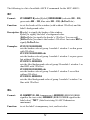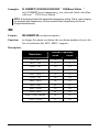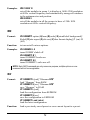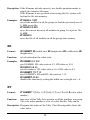
1
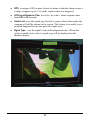
User’s Manual
MCC-8001U
Revision 1.0
(July 2009)
WARNING
Do not attempt to disassemble your MCC-8001U device. Doing so may void your
warranty. There are no serviceable parts inside. Please refer all servicing to
qualified personnel.
TRADEMARKS
All brand and product names are trademarks or registered trademarks of their
respective companies.
COPYRIGHT
The information in this manual is subject to change without prior notice. No part
of this document may be reproduced or transmitted in any form or by any means,
electronic or mechanical for any purpose, without the express written permission
of Avitech International Corporation. Avitech International Corporation may have
patents, patent applications, trademarks, copyrights or other intellectual property
rights covering the subject matter in this document. Except as expressly written
by Avitech International Corporation, the furnishing of this document does not
give you any license to patents, trademarks, copyrights or other intellectual
property of Avitech International Corporation or any of its affiliates.
TECHNICAL SUPPORT
If you have any questions regarding the information provided in this guide, call
our technical support help line at 425-885-3863 or our toll free help line at
1-877-AVI-TECH. You can also email to [email protected]
Table of Contents
Warranty............................................................................................... iii
Extended Warranty Options....................................................................... iv
Services and Repairs Outside the Warranty Period .................................. iv
Regulatory Information........................................................................ v
Federal Communications Commission (FCC) Statement...........................v
European Union CE Marking and Compliance Notices............................. vi
Statements of Compliance ................................................................. vi
Australia and New Zealand C-Tick Marking and Compliance Notice ....... vii
Statement of Compliance .................................................................. vii
Preface ............................................................................................... viii
Welcome .................................................................................................. viii
About this Manual ...................................................................................... ix
1
Getting Started ............................................................................... 1
1.1 Package Contents ...............................................................................1
1.2 Product Features .................................................................................2
Specifications.......................................................................................3
Operating Features..............................................................................4
1.3 Identifying the Front Hardware Component.........................................4
1.4 Identifying the Rear Hardware Components .......................................5
1.5 Getting Your MCC-8001U Ready for Use ...........................................6
Basic Hardware Connections ..............................................................6
Cascading..........................................................................................10
1.6 Using the Galaxy Program ................................................................12
Module Layout Window .....................................................................16
Galaxy Control Window .....................................................................17
Mouse Right-click Menu ....................................................................53
i
2
Avitech ASCII Protocol................................................................ 67
2.1
2.2
2.3
2.4
3
Setting the RS-232 Port.....................................................................67
Setting the HyperTerminal’s COM Port .............................................68
Entering the ASCII Z Command Interface .........................................69
ASCII Z Command Format ................................................................71
ZC.......................................................................................................72
ZL.......................................................................................................72
ZM.......................................................................................................73
ZN.......................................................................................................74
ZP.......................................................................................................74
ZR.......................................................................................................75
ZT.......................................................................................................75
ZX.......................................................................................................76
Firmware Upgrade ....................................................................... 77
3.1 Updating the Firmware ......................................................................77
8668 Firmware...................................................................................77
MCU (8051) Firmware .......................................................................79
3.2 Resetting to the Factory-default State ...............................................80
A
Glossary....................................................................................... 81
ii
Warranty
Avitech International Corporation (herein after referred to as “Avitech”)
warrants to the original purchaser of the products manufactured in its facility (the
“Product”), that these products will be free from defects in material and
workmanship for a period of one (1) year or twelve (12) months from the date of
shipment of the Product to the purchaser.
If the Product proves to be defective during the one (1) year warranty period, the
purchaser’s exclusive remedy and Avitech’s sole obligation under this warranty
is expressly limited, at Avitech’s sole option, to:
(a) repairing the defective Product without charge for parts and labor; or
(b) providing a replacement in exchange for the defective Product; or
(c) if after a reasonable time is unable to correct the defect or provide a
replacement Product in good working order, then the purchaser shall be entitled
to recover damages subject to the limitation of liability set forth next.
Limitation of liability: Avitech’s liability under this warranty shall not exceed
the purchase price paid for the defective product. In no event shall Avitech be
liable for any incidental, special, or consequential damages, including without
limitation, loss of profits for any breach of this warranty.
If Avitech replaces the defective Product with a replacement Product as provided
under the terms of this Warranty, in no event will the term of the warranty on the
replacement Product exceed the number of months remaining on the warranty
covering the defective Product. Equipment manufactured by other suppliers and
supplied by Avitech carries the respective manufacturer’s warranty. Avitech
assumes no warranty responsibility either expressed or implied for equipment
manufactured by others and supplied by Avitech.
This Warranty is in lieu of all other warranties expressed or implied, including
without limitation, any implied warranty of merchantability or fitness for a
particular purpose, all of which are expressly disclaimed.
iii
This Hardware Warranty shall not apply to any defect, failure, or damage:
z
caused by improper use of the Product or inadequate maintenance and care
of the Product;
z
resulting from attempts by other than Avitech representatives to install,
repair, or service the Product;
z
caused by installation of the Product in a hostile operating environment or
connection of the Product to incompatible equipment; or
z
caused by the modification of the Product or integration with other products
when the effect of such modification or integration increases the time or
difficulties of servicing the Product.
Any Product which fails under conditions other than those specifically covered
by the Hardware Warranty, will be repaired at the price of parts and labor in
effect at the time of repair. Such repairs are warranted for a period of ninety (90)
days from date of reshipment to customer.
Extended Warranty Options
Avitech offers OPTIONAL Extended Warranty plans that provide continuous
coverage for the Product after the expiration of the Warranty Period. Contact an
Avitech sales representative or details on the options that are available for your
Avitech equipment.
Services and Repairs Outside the Warranty Period
Avitech make its best offer to repair products that is outside the warranty period,
provided the product has not reached its end of life (EOL). The minimum charge
for such repair excluding shipping and handling is $200 (US dollars).
iv
Regulatory Information
NOTE: Marking labels located on the exterior of your device indicate the regulations that
your model complies with. Please check the marking labels on your device and refer to the
corresponding statements in this chapter. Some notices apply to specific models only.
Federal Communications Commission (FCC)
Statement
This equipment has been tested and found to comply with the limits for a Class A
digital device, pursuant to Part 15 of the FCC Rules. These limits are designed to
provide reasonable protection against harmful interference when the equipment
is operated in a commercial environment. This equipment generates, uses, and
can radiate radio frequency energy and, if not installed and used in accordance
with the instruction manual, may cause harmful interference to radio
communications. Operation of this equipment in a residential area is likely to
cause harmful interference, in which case the user will be required to correct the
interference at his own expense.
Properly shielded and grounded cables and connectors must be used in order to
meet FCC emission limits. Avitech is not responsible for any radio or television
interference caused by using other than recommended cables and connectors or
by unauthorized changes or modifications to this equipment. Unauthorized
changes or modifications could void the user's authority to operate the
equipment.
Operation is subject to the following two conditions: (1) this device may not
cause harmful interference, and (2) this device must accept any interference
received, including interference that may cause undesired operation.
v
European Union CE Marking and Compliance Notices
Statements of Compliance
English
This product follows the provisions of the European Directive 1999/5/EC.
Danish
Dette produkt er i overensstemmelse med det europæiske direktiv 1999/5/EC.
Dutch
Dit product is in navolging van de bepalingen van Europees Directief
1999/5/EC.
Finnish
Tämä tuote noudattaa EU-direktiivin 1999/5/EC määräyksiä.
French
Ce produit est conforme aux exigences de la Directive Européenne 1999/5/EC.
German
Dieses Produkt entspricht den Bestimmungen der Europäischen Richtlinie
1999/5/EC.
Greek
To προϊόν αυτό πληροί τις προβλέψεις της Ευρωπαϊκής Οδηγίας 1999/5/EC.
Icelandic
Þessi vara stenst reglugerð Evrópska Efnahags Bandalagsins númer 1999/5/EC.
Italian
Questo prodotto è conforme alla Direttiva Europea 1999/5/EC.
Norwegian
Dette produktet er i henhold til bestemmelsene i det europeiske direktivet
1999/5/EC.
Portuguese
Este produto cumpre com as normas da Diretiva Européia 1999/5/EC.
Spanish
Este producto cumple con las normas del Directivo Europeo 1999/5/EC.
Swedish
Denna produkt har tillverkats i enlighet med EG-direktiv 1999/5/EC.
vi
Australia and New Zealand C-Tick Marking and
Compliance Notice
Statement of Compliance
This product complies with Australia and New Zealand's standards for radio
interference.
vii
Preface
Welcome
Congratulations on purchasing this Avitech MCC-8001U.
The MCC-8001U Multiviewer is an image scaler / processor designed to accept
either one or two HD / SD-SDI / composite (PAL / NTSC) inputs. Offering
output resolutions up to 1920×1200 (50/60 Hz), it also provides on-screen labels,
borders, and tally indicators, offering a fully integrated on-screen display for
visual monitoring.
The MCC-8001U features 3D 10-bit comb filters (only applies to composite
inputs), which separate brightness and color signals more efficiently in a 3D
domain. It eliminates cross-color, cross-luminance, and dot-crawl distortion – all
of which detract from the visual monitoring experience.
Using the latest DCDi™ technology from Faroudja, DCDI is a video mode
algorithm that stands for Directional Correlation De-interlacing. It’s function is
to help optimize full screen mode regardless of the input format.
Your MCC-8001U can be used as a standalone unit, or cascaded (daisy-chained)
with MCC-8004 modules to provide facility-wide computer and video
monitoring capabilities (up to 15 modules).
viii
About this Manual
This manual contains comprehensive information of your Avitech MCC-8001U
to help you operate the device.
Throughout the manual, the following conventions are used to distinguish
elements of text.
NOTE: provides additional hints or information that requires special attention.
CAUTION: identifies important information which, if not followed, may result in loss of data
or damage to your device.
Any name of menu, command, icon or button that you can see on the screen is
shown in a bold typeset. For example:
On the Start menu, select Settings.
ix
1
Getting Started
This chapter introduces you to the features and specifications as well as the
external components of your Avitech MCC-8001U. It also guides you through
the process of setting up your MCC-8001U for use.
NOTE:
z MCC stands for Media Control Center.
z Depending on the model you purchased, the cabinet color and the look of the
accessories may be different from the ones shown in this manual.
1.1 Package Contents
After unpacking the shipping carton, you should find these standard items:
Avitech MCC-8001U
DVI-to-VGA Adapter
12 V DC Power Adapter
Standard Power Cord (US customers only)
RJ-50 GPI Terminal Block
RJ-45 Looping Cable
(optional – when purchasing 2 or more MCC-8001U)
1
USB to RS-232 converter cable with driver disc
Ear (optional – already installed on MCC-8001U upon
order for assembly on to rack mount)
Blank Panel (optional – already installed on MCC-8001U
upon order for assembly on to rack mount)
Set of screws (optional)
Utility Disc (contains software and user’s manual)
1.2 Product Features
z
Automatic sensing of HD-SDI / SD-SDI and composite analog input.
z
Minimal processing delay of less than one frame.
z
Automatic detection of aspect ratio – 16:9 and 4:3.
z
Up to 26 internal configuration presets.
z
On-screen display of customized labels, borders, and video alarms (future
option).
z
Supports direct TSL Tally / UMD interface.
z
Communication control via RS-232.
z
Compatibility with Galaxy software for configuration, monitor layout, and
multiple-system control.
2
z
Avitech ASCII Protocol (AAP) support.
Specifications
Parts
Inputs
Specifications
Video
Automatic sensing via BNC
HD-SDI (1080i/59.94, 1080i/60, 1080i/50, 720p/59.94, 720p/60,
720p/50)
SD-SDI (NTSC/525i, PAL/625i, 525p/59.94, 625p/50)
Composite analog (NTSC, PAL)
Number of inputs:
(for MCC-8001U-1) one automatic detection HD / SD-SDI /
composite video (PAL/NTSC)
(for MCC-8001U-2) two automatic detection HD / SD-SDI /
composite video (PAL/NTSC)
(for MCC-8001U-4) four automatic detection HD / SD-SDI /
composite video (PAL/NTSC)
NOTE: Input source for 720p supports 60 Hz only.
Output
Resolution from 1024×768 up to 1920×1200 (WUXGA) via DVI-I
connector, simultaneous DVI and RGB
GPI
8 inputs
Number of output: 1, 2, or 4
Data input/ output
Serial port
Number of port: 1
Baud rate: up to 1 Mbaud
RS-232 / 422 supporting TSL
RS-485
Power supply
Number of ports: 2
Consumption less than 30 watts
100~250 V, 50/60 Hz (external)
12 V DC
Housing
Dimension (W×D)
Metal
½ rack
203×254 mm (8×10 inch)
Weight
Environment
Temperature
Operating: 0 °C (32 °F) to 40 °C (104 °F)
Storage: –10 °C (–4 °F) to 50 °C (122 °F)
0 % to 80 % relative, non-condensing
FCC / CE / C-Tick, Class A, UL
2.3 kg (5 lbs)
Humidity
Safety regulations
3
Operating Features
z
Standalone operation (single MCC-8001U) with control via RS-232 cable
or; multiple operation (up to 15 MCC-8001U/MCC-8004 – 14 RJ-485
cascade maximum).
z
Two MCC-8001U can fit in a single rack unit space for a maximum of eight
video inputs.
z
RJ-50 GPI terminal block adapter is provided for Tally or loading presets.
z
Up to 26 presets/configurations can be saved and recalled from the module’s
Flash EEPROM.
z
Compatible with MCC-8004 modules.
1.3 Identifying the Front Hardware Component
n
Ref
n
Component
Power LED
Description
Lights green when the MCC-8001U is powered on.
4
1.4 Identifying the Rear Hardware Components
n
p
o
s
t
u
q
r
v
Ref
Label/Component
n
o
DVI-I Output #1 / 2 / 3 / 4
DVI-I connectors for output to display monitors.
Description
Video Input 1 / 2 / 3 / 4
BNC connectors for HD / SD-SDI / Composite video
inputs.
p
q
r
s
12V DC
Power connector for connecting the power adapter.
RS-232
RS-232 connector for signal from PC.
100-250V AC
Power jack for connecting the AC power cord.
ID
Rotary dial to assign unique addresses in systems
with two or more units.
t
u
v
GPI
RJ-50 connector for GP input/output.
RS-485 (in) (out)
RS-485 connectors for serial cascading input/output.
Dip switches
For updating the firmware.
5
1.5 Getting Your MCC-8001U Ready for Use
Basic Hardware Connections
Perform the following steps to get your MCC-8001U series up and running:
NOTE: The steps outlined next would depend on the type of configuration you wish to set
up.
1. Connect up to four BNC cables to the four Video Input 1 / 2 / 3 / 4 ports for
HD / SD-SDI / Composite video inputs.
2. Connect the RS-232 cable to the RS-232 port for signal from PC and for
using the computer’s Galaxy program to perform setup on the MCC-8001U
(you may need to use a USB to RS-232 converter cable for computer with
USB input/output only – see the next section on installing the USB to
RS-232 converter cable driver).
3. Connect the DVI-I cable to the DVI-I Output #1 / 2 / 3 / 4 port for video output
to the monitor display (you may need to use a DVI-to-VGA adapter for
monitor display with VGA input).
4. Make sure to assign a unique address to your MCC-8001U ID rotary dial
when connecting to systems with two or more units.
5. Connect the RJ-50 cable to the GPI port for GP input/output.
6. Connect the AC power cord to the 100-250V AC power jack.
Installing the USB to RS-232 Converter Cable Driver
Perform the following steps to install the driver:
1. Upon connecting the USB to RS-232 converter cable to the USB port on
your computer, the computer’s Plug-n-Play feature will detect the new
device and request for the device driver.
2. Place the Driver and User’s Guide (Transfer Series) mini-disc on the optical
drive and the autorun program would automatically start. If you need to start
the program manually, run the autorun.exe program of the driver disc.
6
3. The Driver and User’s Guide window appears on screen. Select by clicking
the mouse on the USB to RS-232 Cable Product Driver and follow the
onscreen instructions to complete the driver installation. The User Manual is
also included on the driver disc.
7
4. After successfully installing the device driver, the computer can now detect
the USB to RS-232 converter cable device name. To check, click Start Æ
Control Panel. Double-click the System icon and when the System Properties
screen appears, select the Hardware tab and then click the Device Manager
button.
8
5. The following screen should show Prolific USB-to-Serial Comm Port (COM3).
6. Double-click on this item and the following screen appears. Select the Port
Settings tab and then click the Advanced button.
9
7. Make sure that the COM Port Number is set to COM1, then click OK.
Cascading
To cascade two Avitech MCC-8001U, perform the following steps:
1. Set the Rotary ID on the first Avitech MCC-8001U to 0 and set the Rotary ID
on the second Avitech MCC-8001U to 1 (can be other values as long as both
are different from each other’s setting).
ID 0
ID 1
IMPORTANT: When cascading two or more modules (up to 15 maximum), make sure each
module gets assigned a unique rotary ID, or it will cause input conflicts.
10
2. Connect one end of the RS-485 cable to the RS-485 (out) port of
MCC-8001U ID 0 and the other end to the RS-485 (in) port of MCC-8001U
ID1.
ID 0
ID 1
RS-485 output (ID 0) to RS-485 input (ID 1)
3. Connect one end of the DVI cable to the DVI-I Output #1 / 2 / 3 / 4 port of
MCC-8001U ID 1 and the other end to the monitor display (you may need to
use a DVI-to-VGA adapter for monitor display with VGA input).
ID 0
Connect to display monitor
ID 1
4. Connect one end of the RS-232 cable to the computer’s RS-232 port and the
other end to the RS-232 port of MCC-8001U ID 0 (you may need to use a
USB to RS-232 converter cable for computer with USB input/output only).
ID 0
Connect to computer
ID 1
5. Connect the power cables to the two MCC-8001U and make sure that power
is available.
Connect to power
Connect to power
IMPORTANT: When cascading with MCC-8004 module, the MCC-8001U becomes slave
to the MCC-8004 so make sure to set the baud rate of the MCC-8001U to 57600 bps before
cascading (see the later section for instructions on setting the baud rate).
11
1.6 Using the Galaxy Program
The Galaxy program is designed to be used with Avitech Multiviewer modules.
A small yet powerful program, it uses very little system resource and will not
take up much hard drive space; best of all, no installation is required. This
software can be used on your PC or laptop computer and may even be run
through an external portable device but should not be run from a “read-only
device” such as an optical disc. This section introduces the Galaxy program for
setting up your system.
NOTE: Make sure the MCC-8001U is powered on and connected properly to your
computer (see previous section) before launching the Galaxy program.
To optimize the usage of your Avitech MCC-8001U, perform the following
steps to configure it using the Galaxy program:
1. Use the serial cable to connect by configuring your computer’s COM port to
be 1 ~ 10.
2. Run the Galaxy program by double-clicking the Galaxy-V311.exe file.
When the following screen appears, under Serial Port select Automatically
Search, then click the MCC8001 check box.
NOTE: The MCC-8001U does not support IP as the communication mode.
3. Click OK and your computer would start to search for your MCC-8001U.
NOTE:
z If you have two or more modules cascaded, they should also be detected.
z Make sure that the slave module’s baud rate and resolution is the same as the master
module’s.
12
4. Upon finding your device, the following screen appears to confirm
connection to your MCC-8001U.
For standalone module
For cascaded modules
NOTE: Make sure the cascaded modules have different rotary ID settings (e.g., 1 – 2 – 3)
on their rear panels.
13
5. Click OK and the following screens appear: Module Layout window, Galaxy
control window, and Option window.
z
Module Layout window contains the bird’s eye view of the module layout
belonging to each ID in the system. In this example, the left window
displays the layout belonging to ID:1 on the Galaxy control window, the
middle window displays the layout belonging to ID:2, while the right
window displays the layout belonging to ID:3.
14
z
Galaxy control window is for creating and configuring the layout.
NOTE: When entering the Galaxy program for the first time, the layout for ID: 2 and ID: 3
will be covered by ID: 1.
On the blue information bar portion can be found the following items:
z
Logo icon Avitech Galaxy: proprietary logo and the name of the
software.
z
1280×1024 (60Hz): shows the current output resolution and
frequency.
z
Baud: 57600 bps: shows the current COM port baud rate.
15
z
Option window is for group and window/label setup, save/load file, and
adjust image. (Refer to a later section for details.)
Module Layout Window
Layout Menu
Select from 2×2, 3×3, or 4×4 (left to right or top to bottom) as possible grid
positions on the Module Layout window.
16
Galaxy Control Window
Select Menu
Open Option Menu
Toggles the Option window display on (with check mark) / off.
Dock Option Menu
Returns the Option window display to its default position on the right side of the
Galaxy control window. This option is not available (grayed out) if the previous
item Open Option Menu is disabled.
Settings Menu
17
Set Output Mode
Changing the output resolution affects all the modules in the selected group. If
you have more than one group, make sure you select the correct Group on the
drop down menu. The MCC-8001U default output resolution is 1280×1024 /
60 Hz.
18
1. Click Settings, then click Set Output Mode.
2. When the following screen appears, set the output resolution to match the
display monitor’s. Select the Refresh Frequency, select the Mode from the
drop-down menu, then click OK. You will notice that the selected resolution
is displayed on the top bar of your Galaxy program.
19
Reconnect (Serial Port)
When you have unplugged the serial cable and re-connected it, click Reconnect
(Serial Port) to continue the configuration process.
20
System Parameter
The following setup affects all the modules of all the groups. Upon clicking
System Parameter, the menu appears as shown next:
Return Group Index to Default
Allows you to return all groups to their default setting as well as combine all
modules into one group. Click OK when the next screen appears to complete
the configuration change.
21
One Module Per Group
By default, the Galaxy program will combine all available modules into one
large group. To quickly divide modules into different groups, each module
can be treated as a group. For example if cascading four modules then it will
be divided into four groups. When the next screen appears, click OK to
finalize the changes.
The configuration progress will be shown on screen.
22
Or, another method for creating new groups is:
1. Right-click the mouse on the module you wish to add to the new group.
Then click Set ID# To Æ New Group.
2. Repeat for all additional modules (you can either add additional modules
to the new group or create additional groups).
23
3. To switch between the different groups, use the Group drop down menu.
4. Exit the Galaxy program and select Yes when prompted to save to flash
memory
Save System Files to Flash
Allows you to save all configuration settings to flash memory. If the system
configuration has been changed, save the changes first before continuing the
other configuration settings. The progress of saving to flash memory will be
displayed.
24
Turning On/Off All Labels/TSL
To turn on/off all labels / TSL for all the modules regardless of the group it
belongs to, click ON/OFF.
Module Cascade Series
The DVI Switch function is not available for your MCC-8001U. Use the
Cascade Series function to change the ID number designation only, this will
not affect the actual physical connection of the MCC-8001U.
25
Advanced
Upon clicking Advanced the following screen appears:
z
Use Broadcast Load File
For loading preset / switching resolution / group reset. When this option
is enabled (with checkmark), the Galaxy program will broadcast the
command to every module, allowing for simultaneous execution of the
command.
NOTE: This feature should always be enabled.
z
Automated Backup Files to Hard Drive
By default, the Galaxy program will save all backup files to the
C:\Avitech_MCC\BackUp\ folder. You may change this by
clicking Browse to select a different location to save the backup
information.
z
No Signal size refer to
When the window is unable to detect a signal, this will serve as the basis
for the Galaxy program to adjust the window size. NTSC: maximum
window size is 816×465. PAL: maximum window size is 816×560.
Clear Alarm Message (Locked State)
Use this function to remove all the alarm messages that were previously
saved.
26
Clear Tally Status
When running Tally via RS-232, use this function in the Galaxy program to
close it. If not, then use the ASCII Z command to close Tally via RS-232.
Group Parameter
The following setup affects all the modules in the selected group only. Upon
clicking Group Parameter, the menu appears as shown next:
Group Reset
Allows you to refresh all modules belonging to the same group.
Label
There are two hierarchies for setting the Label properties. One can affect the
entire group, while the other affects a single window.
27
For an Entire Group
To set the label properties, perform the following steps:
NOTE: Make sure to turn on all labels (see previous section) before setting the label
properties.
Select Settings Æ Group Parameter Æ Label to adjust the Font Color, B-G
(background) Color, and font Size for all labels in the group.
28
For an Individual Window
1. Right-click the mouse on a window and select Label to enter in the text.
2. Keep in mind that each window supports one line of text up to 30
characters.
29
z
OSD Position: allows you to change the vertical position of the label by
clicking above or below the blue line (default is 1).
z
Label Outside: allows you to place the label outside of the window.
z
Fill Background: allows the label background to fill the entire width of the
window.
z
Text Transparency Switch: allows you to set the transparency level of the
entire label including the background.
z
BMP Label: allows you to activate the Asian fonts for labels by
performing the following steps –
1. Click to enable the BMP Label checkbox (with check mark).
2. Click the BMP Label Font Type button.
3. When the Font window appears, set the Font, Font style, and Size.
Then click OK.
4. To enter a label for the window, right-click the mouse on a particular
window and on the menu that appears, click Label.
5. On the Label Properties – Process window, make sure to enable the
BMP Label checkbox (with check mark).
6. On the Line 1 window enter a label in the desired language by first
selecting the language on the Windows taskbar.
7. Repeat the above steps for all the other windows.
30
Setting Border Properties
Borders are turned on by default, to turn off the border perform the following
steps:
For an Entire Group
1. Select Settings Æ Group Parameter Æ Border, and then change the
Border Width to 0.
2. You can also change the border color.
z
Each pixel/line can have a different color
z
3D border
31
For an Individual Window
To change the border properties for an individual window, right-click the
mouse on the window and select Border, then select the desired color and
size.
Activating Tally
The RJ-50-to-GPI terminal block allows for a total of eight inputs to activate
tally, two per window. You can also use the serial port with ASCII, TSI, or
TSL to activate the tally. To change the appearance of the tally, perform the
following steps:
1. Select Settings Æ Group Parameter Æ Tally. The following window
appears:
Tally 1 and 2 are triggered by GPIO. MCC-8001U only supports Tally 1
and Tally 2.
2. The settings that can be adjusted include Tally Color, Label, Border, and
Flash.
NOTE: Tally 1 and Tally 2 can trigger either Label or Border, but there is only one border or
label. If both Tally 1 and Tally 2 are triggered simultaneously, the display priority will be
Tally 1 then Tally 2.
32
Setting Alarm Properties
Allows you to setup the notification when a signal is missing.
For an Entire Group
To set the alarm properties, select Settings Æ Group Parameter Æ Alarm to
set the Process/Video Alarm Switch, adjust the Signal Type’s Font Color and
B-G (background) Color for alarm in the group. You can also lock the video
alarm.
For an Individual Window
To set the alarm properties for an individual window, right-click the mouse
on the window and select Set Alarm.
z
Module/Process Alarm Switch: to turn on the alarm setting, make sure that
both options are enabled (with check mark).
z
Video Alarm Switch: to turn on/off the “no video” signal. You may set the
image border to be Red or to Flash as warning.
33
z
GPO: to assign a GPO contact closure to alarm so that the alarm creates a
voltage (supports up to 5 V) on the contact when it is triggered.
z
All Process Response Time: to set the “no video” alarm response time
from 0.23 to 23 seconds.
z
Alarm Lock: once the signal gets lost but re-gains it back afterwards, the
warning will still be shown on the screen. This feature is to notify you a
problem happened but no one noticed it right away.
z
Signal Type – sets the signal’s font and background color. When this
option is enabled, the video’s signal type will be displayed on the
monitor display.
34
To clear the alarm lock message, select Settings Æ System Parameter Æ
Clear Alarm Message (Locked State).
NOTE: For MCC-8001U-2 / -4, the GPO alarm will be activated when any of the two / four
modules lose the signal source.
Setting COM Port
By default the COM port is set to normal and baud rate set to 57600 bps to
configure the serial port of the module with PC for configuration and control.
To set the COM port, perform the following steps:
1. Select Settings Æ Group Parameter Æ COM A. The following screen
appears.
35
2. Select the Setting COM A option.
3. Set the Baud Rate.
NOTE: When cascading with the MCC-8004, the baud rate should set to 57600 bps.
4. Select the Mode.
z
Normal – for configuring the serial port of the module with PC
configuration and control.
z
TSL – for configuring the serial port of the module with TSL
connection. The initialization process is different so the same TSL
connection for other Avitech products may not function correctly
with the MCC-8001U without additional changes
5. After setting COM A, you may be prompted to close the Galaxy program
and power cycle (shutdown and restart) the module.
Safe Area
Select Settings Æ Group Parameter Æ Safe Area and the following screen
appears.
36
The following should be noted when setting the safe area:
z
Luminance is reduced outside the safe area.
z
Enable – can be enabled/disabled for each source window. By using the
slider, freely adjust the horizontal (Left and Right) and vertical (Top and
Bottom) markers.
z
Display 4:3 markers – fixed 4:3 markers (vertical yellow lines) delineates
the 4:3 area in a 16:9 window.
TSL
The MCC-8001U includes one RS-232 port that is used for connecting to a
PC for configuration control and connecting to TSL controller. One TSL port
of the TSL controller is needed for connecting to the first module of each
group. To setup the configuration, perform the following steps:
1. Select Settings Æ Group Parameter Æ COM A.
37
2. On the Mode drop-down menu select TSL. The Baud Rate will
automatically adjust to 38400 bps (according to TSL specifications).
3. Save and exit the Galaxy program – this can also be done once all the
parameters have been configured.
38
4. By default all windows are enabled for the TSL protocol. This can be
changed for an individual window, on a group basis, or at the system
level by clicking Settings Æ System Parameter.
39
5. Click All TSL, then select ON/OFF.
For an Entire Group
1. Select Settings Æ Group Parameter Æ TSL.
2. Ensure that Enable is selected (with checkmark). If it is unchecked, only
static labels will be displayed.
40
3. Specify the Display Address (ranges from 0 to 126). The address should
match the TSL controller configured address corresponding to the router
output feeding the corresponding Avitech input.
4. If you want to display dynamic labels then click the radio button to select
TSL Only. If you want to display both the static and dynamic labels, click
the radio button to select Allow Both Static & Dynamic.
5. To display 8 or 16 dynamic characters (in case the TSL implementation
allows it), click the radio button to select the corresponding options. This
concludes the TSL setup on the group level.
For an individual window
Perform the above same steps for each window by right-clicking the mouse
on each individual window, then clicking TSL to set the TSL Display Address.
NOTE: When dynamic labels are displayed, bitmap fonts cannot be used for displaying
static and/or dynamic labels.
Output Timing
There are two output timings namely Normal and VESA. Normal output
timing is designed for some brands of display monitors which do not support
the VESA standard. The default setting for output timing is Normal.
41
Frame Lock
Allows the output display to be synchronized with the input source. When
frame lock is enabled (On), the modules help maintain image continuity to
create a virtual canvas. Default setting for Frame Lock is Off.
NOTE: Before switching to a different input source on the MCC-8001U, make sure Frame
Lock been turned Off.
42
Module Parameter
The following setup affects the selected module only. Upon clicking Module
Parameter, the menu appears as shown next:
Output Timing
There are two output timings namely Normal and VESA. Normal output
timing is designed for some brands of display monitors which do not support
the VESA standard. The default setting for output timing is Normal.
43
Activating Tally
The RJ-50-to-GPI terminal block allows for a total of eight inputs to activate
Tally, two per window. You can also use the serial port with ASCII, TSI, or
TSL to activate the Tally. To change the appearance of the Tally, perform the
following steps:
1. Select Settings Æ Module Parameter Æ Tally. The following window
appears:
Tally 1 and 2 are triggered by GPIO while Tally 3 is triggered via serial
communication.
2. The settings that can be adjusted include Tally Color, Label, Border, and
Flash.
44
GPI Definitions
Eight positions can be found on the RJ-50-to-GPI terminal block that are
assignable to either activate Tally (two per video input) or to load presets, but
each pin can only be assigned to one task. To assign the definition of each
GPI, perform the following steps:
1. Upon clicking GPI Definitions, the following screen appears:
2. After you have finished assigning tasks to each GPI, click OK to finalize
the changes.
45
NOTE:
z The RJ-50-to-GPI terminal block adapter has eight positions that can each be used for
setting Tally and loading presets.
z By default, the terminal block is used to turn on/off the Tally for each window:
– Position 1 + GND = turns on main Tally for window 1.
– Position 2 + GND = turns on secondary Tally for window 1.
– Position 3 + GND = turns on main Tally for window 2.
– Position 4 + GND = turns on secondary Tally for window 2.
– Position 5 + GND = turns on main Tally for window 3.
– Position 6 + GND = turns on secondary Tally for window 3.
– Position 7 + GND = turns on main Tally for window 4.
– Position 8 + GND = turns on secondary Tally for window 4.
Frame Lock
Allows you to turn on (with checkmark) or off the output display to be
synchronized with the input source. When frame lock is enabled, the
modules help maintain image continuity to create a virtual canvas. Click on
the item to toggle between on/off.
Importing / Exporting Label
Allows you to import label from / export label to Microsoft Excel or Notepad to
be edited externally.
46
The convenient way is to export the file (label) as a BMP Label (Unicode) or Label
(ANSI) txt file by assigning a filename when the next screen appears.
By using Microsoft Notepad, edit the text in the file starting with Group 1 and
Module 1. When you are done editing the label (highlighted in red below) save
the txt file and import it. The on screen labels will then be updated.
47
Help Menu
Read BIOS Version
To find out the Avitech MCC-8001U module firmware version, perform the
following steps:
1. Click Help, then click Read BIOS Version.
48
2. When the following screen appears, click Export.
3. Assign a filename and click Save to save the data.
Backing Up Presets
To backup a preset, perform the following steps:
1. Click Help, then click Backup All Information.
49
2. The following warning message appears, click OK to continue.
3. The following message appears when back-up is successful, click OK to
continue.
This will backup all saved presets and system configuration files to
c:\Avitech_MCC\Backup\XXXX#_#
WARNING: Everything in the Backup folder will be erased. If you have previously backed
up presets, they will all be written over when you backup presets again. If you want to keep
the old presets, move the entire Backup folder to a temporary directory (e.g., c:\temp).
This will create the following directories:
– c:Avitech_MCC\Backup\
– c:Avitech_MCC\Temporary
50
Restoring Presets
To manually restore a preset, perform the following steps:
1. Click Help, then click Restore Module Information. You should see a progress
bar showing the preset being loaded into the MCC-8001U.
2. When the following screen appears, confirm if the backup Path is correct.
Then click Restore.
51
If incorrect, click Browse to select the correct location. Then click OK to
continue.
3. Click OK when the next screen appears to continue.
4. Click OK when the next screen appears to restart the Galaxy program.
52
Read Galaxy Information
1. Click Help, then click About.
2. You should see a pop-up box showing the Galaxy program information.
Mouse Right-click Menu
To change the properties of an individual window, right-click the mouse on the
particular window to access the window’s menu.
53
Check Signal
To display the video signal being fed into the selected window, right-click the
mouse on a particular window and click Check Signal. The following screen
appears.
Turning On/Off the Label
1. The Option window has a check box that can be used to turn off the label (L)
for each window.
2. To turn off a label, find the check box that represents the selected window
and check to enable or un-check to disable the Label.
54
3. Upon right-clicking on a particular window, select Label and the following
screen appears. Refer to a previous section for details on setting the Label
Properties.
NOTE: When output resolution is set to 800x600, the label size can support up to two (36
pixels) only.
55
Turning On/Off the Border
Allow you to change the properties for the border. Upon right-clicking on a
particular window, select Border and the following screen appears. Refer to a
previous section for details on setting the Border Properties.
Displaying Static / Dynamic Labels
Allows you to display static/dynamic labels by right-clicking on a particular
window, select TSL and the following screen appears. Refer to a previous section
for details on setting the TSL Properties.
56
Aspect Auto Detect
Allows you to set the input signal’s aspect ratio of a particular window. If the
input signal is of a different aspect ratio than the display monitor in which it is
displayed, you may change the monitor’s aspect ratio to display the signal
without deformation.
1. Click the mouse to select Enable and then select the desired aspect ratio.
2. Then click OK. The available selections for HD-SDI is 16:9; while for SD-SDI /
Composite you can switch between 4:3 and 16:9.
Setting the Safe Area
Allows you to adjust the safe area for all four margins. Refer to a previous
section on setting the Safe Area.
57
Setting the Alarm Properties
Allows you to setup the notification when a signal is missing. Refer to a previous
section on setting the alarm properties.
Saving to a Flash File
There are two instances that you will need to use the save to flash feature:
z
After creating the master layout and you want the MCC-8001U to load it
again when the unit is power cycled (shutdown and restart).
z
After you are done saving presets and you want to save all the presets that
were created into the internal flash memory of the module. If this action is
skipped, the module will lose all the presets that were created.
58
To save to flash, perform the following steps:
1. Click Save File on the Option window.
59
2. Click Update to Module Flash, then click OK.
Or, close the Galaxy program and select Yes when prompted to save.
Saving a Preset
All the presets you create are stored in the MCC-8001U and not in the computer
that is running the Galaxy program. In order to write all the presets into the
internal flash memory of the MCC-8001U after creating it, you will need to save
to flash. To save a preset, perform the following steps:
1. Configure the layout to how you want it to display.
60
2. Click Save File on the Option window.
61
3. Enter a unique filename for the preset and select OK to save.
When using the GPI, use the numbers 1 ~ 8 for your preset names.
The file extension GP# will be automatically added to the file name.
4. Repeat the above steps for each additional presets.
5. After you are done creating presets, load the file that you want to be the
master layout, which gets loaded when the MCC-8001U is powered on.
6. Close the Galaxy program and select Yes when prompted to save to flash.
62
Loading File
1. In the Option menu, click Load File.
63
2. Select a saved file then click OK to load the preset.
64
Making Adjustments
1. In the Option menu, click Adjustment.
65
2. The following screen appears.
3. You can adjust the input signal such as Brightness (0 ~ 255), Saturation (0 ~
127), Contrast (0 ~ 127), and Hue (–128 ~ 127) parameters directly by using
the sliders. Click the Default button on the lower right portion of the screen to
reset the values to the factory default.
66
2
Avitech ASCII Protocol
The MCC-8001U supports the ASCII command prompt interface, you can use
HyperTerminal to control your MCC-8001U. The serial port (RS-232) on the
MCC-8001U can also be used to interface with a third-party controller for
control over RS-232. This chapter familiarizes you with using the Avitech
ASCII Protocol (AAP) of the MCC-8001U via Microsoft Windows
HyperTerminal function as an example.
2.1 Setting the RS-232 Port
Before using the ASCII Z command interface, make sure that the COM A
(RS-232) port on the MCC-8001U is set at Normal (8-bit data, 1 stop bit, no
parity, and no flow control). The default baud rate is 57600 bps. To correctly use
the ASCII Z commands, use the Galaxy program’s default Group and Module
Number for the MCC-8001U. Refer to the Galaxy program’s User Manual for
details.
67
NOTE:
z To set COM A to Normal. Click Settings Æ Group Parameter Æ COM A. When the
next screen appears, select Normal on the Mode drop down menu. Then click OK.
z Disconnect the SCP keypad if that is connected.
2.2 Setting the HyperTerminal’s COM Port
To set the HyperTerminal’s COM Port, perform the following steps:
1. Click Start Æ All Programs Æ Accessories Æ Communications Æ
HyperTerminal to startup the Windows HyperTerminal function.
2. Set the HyperTerminal’s COM port to the following settings (same as
RS-232 port setting):
z
Baud Rate: 57600
z
Data Bits: 8
z
Parity: None
z
Stop Bits: 1
z
Flow Control: None
68
2.3 Entering the ASCII Z Command Interface
To startup the ASCII Z command interface, perform the following steps:
1. Connect the HyperTerminal’s COM port (PC) to the MCC-8001U RS-232
port and make sure that power supply is available.
2. Connect the power cord to the MCC-8001U so that it will use the default
baud rate (57600 bps) to transmit the startup signal.
69
3. Press Enter to login to the ASCII Z command interface. When the
HyperTerminal’s command prompt “>” symbol appears, you can start
entering ASCII Z commands.
4. To logout of the ASCII Z command interface, type exit and press Enter.
70
2.4 ASCII Z Command Format
The ASCII Z command is comprised of the following parts:
Header
Group/Module/Window Assignment
Parameter 1
Parameter 2
...
The following is a list the rules to follow when entering the ASCII Z command:
z
It is acceptable to enter commands in small or capital letters, and the five
columns are separated by a space.
z
Header = z + command character
z
Group/Module/Window Assignment (GGMMPP) = is comprised of six Arabic
numerals. This is used in designating the device’s Group/Module/Window
Assignment.
Group = is comprised of the first two numbers (01 ~ 99), 00 is used to
pertain to all groups.
Module = is comprised of the middle two numbers (01 ~ 15), 00 is used to
pertain to all modules.
Window Assignment = is comprised of the last two numbers (01 ~ 04), 00 is
used to pertain to all window assignments.
z
Parameter 1 of color assignment (RRRGGGBBB) = is comprised of nine
Arabic numerals, this is used in designating the color.
z
Parameter 2 of on/off switch = “1” signifies ON while “0” signifies OFF.
NOTE: Each video input will occupy a whole display, so each video will be treated as one
group. For example, the MCC-8001U can accept two inputs at the same time, so
MCC-8001U will be recognized as two groups, and for each group there will be only one
module (MM) and one processing video (PP). If cascading three MCC-8001Us together,
the corresponding format for output #1 from the third MCC-8001U (rotary ID #2) will be:
050101.
71
The following is a list of available ASCII Z commands for the MCC-8001U:
ZC
Format:
ZC GGMMPP B[order]/L[abel] RRRGGGBBB (red ratio 000 ~ 255,
green ratio 000 ~ 255, blue ratio 000 ~ 255) (NoDimColor)
Function:
to set the border of the window (with/without 3D effect) and the
label’s background color.
Description: B[order] to signify the border of the window.
L[abel] to signify the label’s background color.
[NoDimColor] to signify the border’s 3D effect. You can add
[NoDimColor] to remove the border’s 3D effect. Just enter NDC to
signify NoDimColor.
Examples:
ZC 010101 B 000255000
sets the border color of group 1 module 1 window 1 as dim green
with 3D effect.
ZC 010101 B 000255000 ndc
sets the border color of group 1 module 1 window 1 as pure green
but without 3D effect.
ZC 200101 L 255000000
sets the label background color of group 20 module 1 window 1 as
dim RED with 3D effect
ZC 020202 B 255000000 ndc
sets the border color of group 2 module 2 window 2 as red but
without 3D effect.
ZC 030303 L 000000255
sets the label background color of group 3 module 3 window 3 as
blue with 3D effect.
ZL
Format:
ZL GGMMPP 00~255 (transparency) 000000000 (RRRGGGBBB
signifies the text color) 000000000 (RRRGGGBBB signifies the
label color) “TEXT” (label text string 50 ASCII characters
maximum)
Function:
to set the label’s transparency, text, and text color.
72
Examples:
ZL GGMMPP 0 255000000 000000255 “ CNN News Station ”
sets GGMMPP to no transparency, text color red, label color blue,
with text “ CNN News Station ”.
NOTE: All windows will share the same label transparency setting. That is, upon changing
one window’s label transparency, all other window’s label transparency will also be
changed simultaneously.
ZM
Format:
ZM GGMMPP ## (resolution number)
Function:
to change the output resolution, the resolution number refers to the
list of resolutions the MCC-8001U supports.
Description:
Vertical Frequency
Resolution
50 Hz
60 Hz
800 × 600
42
1
1024 × 768
31
2
1280 × 720
30
15
1280 × 768
32
22
1280 × 1024
29
9
1360 × 768
38
20
1400 × 1050
34
35
1440 × 900
46
45
1600 × 1200
39
10
1680 × 1050
41
40
1920 × 1080 (1080p)
28
26
1920 × 1200
37
36
73
Examples:
ZM 010000 10
sets all the modules in group 1 to display at 1600×1200 resolution
at 60 Hz vertical frequency and automatically arrange all windows
to the optimum size and position.
ZM 000000 9
sets all the modules in all the groups to have a 1280×1024
resolution at 60 Hz vertical frequency.
ZN
Format:
ZN GGMMPP option (A[larm]/B[order]/E[xtend label background]/
L[abel]/R[atio aspect]/S[afe area]/V[ideo format display]) 1 (on) / 0
(off)
Function:
to turn on/off various options.
Examples:
ZN GGMM00 L 0
turns GGMM’s label off.
ZN GGMMPP B 1
turns GGMMPP border on.
ZN GGMMPP S 0
turns GGMMPP’s safe area off.
NOTE: Each ASCII command can only serve one purpose; multiple options on one
command will not be recognizable.
ZP
Format:
ZP GGMMPP L[oad] “filename.GP#”
load “filename” from RAM
ZP GGMMPP S[ave] “filename.GP#”
save “filename” to RAM
ZP GGMMPP L[oad]
load the configuration from EEPROM
ZP GGMMPP S[ave]
save the configuration to EEPROM
ZP GGMMPP Load Latest
load the latest configuration
Function:
load a previously saved preset or save current layout to a preset.
74
Description: If the filename includes space(s), use double quotation marks to
signify the complete filename.
If the filename is not specified when saving the file, system will
backup the file into memory.
Examples:
ZP 000000 L 1.GP1
sets all the modules in all the groups to load the previously saved
1.GP1 preset file.
ZP 020000 S 2.GP2
saves the current layout of all modules in group 2 to a preset file
2.GP2.
ZP 000000 S
saves the file of all modules in all the groups into memory.
ZR
Format:
ZR GGMMPP SD (width rate) SD (height rate) HD (width ratio) HD
(height ratio)
Function:
to lock and adjust the video ratio.
Examples:
ZR GGMM01 4 3 16 9
sets GGMM01 SD video ratio as 4:3, HD video as 16:9.
ZR 000000 16 9 4 3
sets all windows’ SD video ratio as 16:9, HD video as 4:3.
ZR GGMMPP 7 12 7 12
sets GGMMPP’s SD and HD video ratio as 7:12.
ZR GGMMPP 0 0 0 0
disables the function by setting the width rate or height rate = 0.
ZT
Format:
ZT GGMMPP 1 [Tally 1] / 2 [Tally 2] 1 (on) / 0 (off) # (color index
number)
Function:
turn on or off the Tally for a window or all the windows in a group.
The color index number is a list of colors that the Tally can be.
Description: Designate the action of the Tally. The following table shows the
color index.
75
Examples:
Index
Color
1
Null
2
Red
3
Green
4
Yellow
5
Blue
6
Pink
7
Light Blue
8
White
ZT 000000 2 1 6
activate Tally 2 for all the window(s) in all the module(s) for all the
group(s) with pink color.
ZT 010203 1 0
close Tally 1 for group 1 module 2 window 3.
NOTE: Upon changing a Tally color, the same color is applied to the other Tally of the same
module.
ZX
Format:
ZX GGMMPP “label text” (include the quotation marks) # (font size
(where 0 is the current font size, 1 ~ 4 are the available font size) +
background extend (0 is do not extend, 64 is extend) + outside
video (0 is inside video, 128 is outside video)
Function:
to change the label text and font size as well as specify the inner/
outer video.
Examples:
ZX 000000 "Input 1"
Input 1 will appear as the label for all the window(s) in all the
module(s) of all the group(s).
ZX 000000 3
sets all window’s label font size to 3.
ZX 000000 “ Outside video ” 128
Set all windows’ label as “ Outside video ” with outside video.
76
3
Firmware Upgrade
This chapter familiarizes you with updating the firmware of your Avitech
MCC-8001U as well as resetting it to the factory-default value.
3.1 Updating the Firmware
The firmware for MCC-8001U is divided into:
z
8668 firmware
z
MCU (8051) firmware
IMPORTANT:
z When both firmware needs to be updated make sure to perform 8668 firmware update
first.
z Disconnect all cascaded modules; connect only one module at a time.
8668 Firmware
To update the 8668 firmware, perform the following steps:
1. Connect the power cable to the 100-240V AC power jack on the rear panel of
the MCC-8001U and the other end to an electrical outlet.
2. Use a serial (RS-232) cable and connect one end to the MCC-8001U rear
panel’s RS-232 port and the other end to the computer’s serial port side.
77
3. Run the Galaxy program by double-clicking the Galaxy-V311.exe file.
Click Others when the following screen appears.
4. When the following screen appears, select CB (RS232) and on the Style drop
down menu select MCC8001U-8668.
5. Select the COM port number you are using to connect the MCC-8001U to
the PC from the COM drop-down menu.
6. Click to select Chip 1 when using the MCC-8001U-1 or,
click to select Chip 1 and Chip 2 when using the MCC-8001U-2 or,
click to select Chip 1, Chip 2, Chip 3, and Chip 4 when using the
MCC-8001U-4
7. Click the Browse button to specify the location of the firmware file and
select MCC-8001U-4.hex.
NOTE: Make sure that the point-to-point network connection method is being used. Using
this method would help prevent failure during the update firmware process.
8. Click the Update button located on the left lower portion of the screen.
78
9. When the next screen appears, pull off the power cord from the power jack to
shutdown the MCC-8001U, then re-attach the power cord to restart the
MCC-8001U within 15 seconds.
NOTE: Shutdown and startup of MCC-8001U needs to be completed within 15 seconds. If
not then an error message will appear on screen. You will then need to redo steps 4 to 8
again to update the 8668 firmware.
MCU (8051) Firmware
To update the MCU (8051) firmware, perform the following steps:
1. Run the Galaxy program by double-clicking the Galaxy-V311.exe file.
Click Others when the following screen appears.
2. When the following screen appears, select CB (RS232) and on the Style drop
down menu select MCC8001U-MCU (8051).
3. Select the COM port number you are using to connect the MCC-8001U to
the PC from the COM drop-down menu.
79
4. Click the Browse button to specify the location of the firmware file and
select AT-MCC8001-MCU.hex.
NOTE: Make sure that the point-to-point network connection method is being used. Using
this method would help prevent failure during the update firmware process.
5. Push the number 1 dip switch located on the MCC-8001U rear panel
downward to the ON position.
6. Click the Update button located on the left lower portion of the screen.
7. Push back the number 1 dip switch upward to the default position.
8. Reboot (unplug and re-plug the power cord) the MCC-8001U when MCU
(8051) firmware update is successful.
NOTE: Shutdown and startup of MCC-8001U needs to be done to completely update the
MCU (8051) firmware.
3.2 Resetting to the Factory-default State
To reset your MCC-8001U to the factory default state, perform the following
steps:
1. Power-off the MCC-8001U by unplugging the power cord.
2. Push the number 2 dip switch located on the MCC-8001U rear panel
downward to the ON position.
3. Power-on the MCC-8001U by plugging in the power cord for 20 seconds
(make sure that power is available).
4. Power-off the MCC-8001U again by unplugging the power cord.
5. Push back the number 2 dip switch upward to the default position.
6. Power-on the MCC-8001U again by plugging in the power cord.
80
A Glossary
DDC (Display VESA standard for communication between a monitor display
Data Channel) and a video adapter. Using DDC, a monitor can inform a
computer’s video card about its properties, such as maximum
resolution and color depth, to ensure that the user is presented
with valid options for configuring the display.
Group (screen) A collective number of video or image windows showing on a
monitor display. Basically the Group defined here is the display
device that is connected to the last module's DVI-I Output port.
Since the MCC-8001U window is shown in full screen mode
and connected directly to the monitor display, so one module
should be treated as one group. For MCC-8001U-2, there are
two sub modules in this case and should be treated as two
groups.
Latest File
Contains the layout that gets loaded every time the module is
powered on.
Master Module Connects to the PC via RS-232 cable to function as the
controlling module when cascading more than one module.
Module File
the module’s *.sys file contains the module ID / model name /
IP address / Tally configuration data.
Preset File
the preset’s *.gpx file contains the layout/label/border
configuration data.
Rotary ID
A circular dip switch used to set a unique ID to each
Selector Switch MCC-8001U module. The rotary ID selector switch's range
spans from 0 ~ 9 and then from A ~ F. For the Galaxy program
to recognize specific modules in a group, each module in a
group setting HAS to have a unique ID number. When ran, the
program will detect a module’s specific ID and add unity to it.
Therefore, if a module has an ID of 1, the program will detect
it as ID2 while an ID of 2 will be detected as ID3, and so forth.
81
Slave Module
Module that is cascaded with / and controlled by the master
module.
Sub ID
Used in identifying the sub module’s unique ID. For
MCC-8001U-2, there are two sub modules. Sub ID 1 is to
identify the Video Input 1 and DVI-I Output #1 ports; while Sub ID
2 is to identify the Video Input 2 and DVI-I Output #2 ports.
System File
the system *.agi file contains the group number and group
cascading module’s configuration data.
82