1
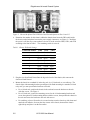
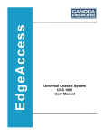
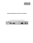
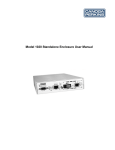
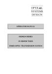
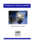
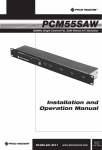
Universal Chassis System
UCS 1002
User Manual
EdgeAccess Universal Chassis System
CAUTION!
This product may contain a laser diode operating at a wavelength of 1300 nm - 1600 nm. Use of
optical instruments (e.g., collimating optics) with this product may increase eye hazard. Use of
controls or adjustments, or performing procedures other than those specified herein may result in
hazardous radiation exposure.
Under normal conditions, the radiation levels emitted by this product are under Class 1 limits in
21 CFR Chapter 1, Subchapter J.
ATTENCION!
Cet équipement peut avoir une diode laser émettant à des longueurs d'onde allant de 1300nm à
1600nm. L'utilisation d'instruments optiques (par exemple : un collimateur optique) avec cet
équipement peut s'avèrer dangereuse pour les yeux. Procéder à des contrôles, des ajustements ou
toute procédure autre que celles décrites ci-après peut provoquer une exposition dangereuse à des
radiations.
Sous des conditions normales, le niveau des radiations émises par cet équipement est en dessous
des limites prescrites dans CFR21, chapitre 1, sous chapitre J.
NOTICE!
This device contains static sensitive components. It should be handled only with proper
ElectroStatic Discharge (ESD) grounding procedures.
NOTE!
Cet équipement contient des composants sensibles aux décharges électro-statiques. Il doit
absolument être manipulé en respectant les règles de mise à la terre afin de prévenir de telles
décharges.
UCS 1002 User Manual
i
EdgeAccess Universal Chassis System
NOTICE
Canoga Perkins has prepared this users manual for use by customers and Canoga Perkins
personnel as a guide for the proper installation, operation and/or maintenance of Canoga Perkins
equipment. The drawings, specifications and information contained in this document are the
property of Canoga Perkins and any unauthorized use or disclosure of such drawings,
specifications and information is prohibited.
Canoga Perkins reserves the right to change or update the contents of this manual and to change
the specifications of its products at any time without prior notification. Every effort has been
made to keep the information in this document current and accurate as of the date of publication
or revision. However, no guarantee is given or implied that the document is error free or that is
accurate with regard to any specification.
Canoga Perkins Corporation
20600 Prairie Street
Chatsworth, California 91311-6008
Business Phone: (818) 718-6300
(Monday - Friday 7 a.m. - 5 p.m. Pacific Time)
FAX: (818) 718-6312 (24 hrs.)
Web Site: www.canoga.com
Email: [email protected]
Copyright © 2002 - 2006 Canoga Perkins Corporation
All Rights Reserved
EdgeAccess®
Universal Chassis System
Model UCS 1002
User Manual
Product Number 6913000
Rev. J 06/2006
MM
EdgeAccess and Canoga Perkins are registered trademarks of Canoga Perkins Corp.
To reference Technical Advisories and Product Release Notes, go to Canoga Perkins'
website: http://www.canoga.com
ii
UCS 1002 User Manual
EdgeAccess Universal Chassis System
Table of Contents
Chapter 1 Overview .................................................................................................1-1
Power Supplies ....................................................................................................................................1-1
Chapter 2 Installing and Setting Up the Chassis ..................................................2-1
Chapter 3 Specifications..........................................................................................3-1
Physical Specifications........................................................................................................................3-1
Regulatory Compliance .......................................................................................................................3-1
Appendix A Warranty ............................................................................................A-1
List of Figures
Figure 1. UCS 1002 Chassis...............................................................................................................1-1
Figure 2. Chassis Backplane With CID Switch and Ground Options at Slots 14 and 15...................2-2
List of Tables
Table 1. Chassis ID Switch Settings...................................................................................................2-2
UCS 1002 User Manual
iii
EdgeAccess Universal Chassis System
iv
UCS 1002 User Manual
EdgeAccess Universal Chassis System
Chapter 1
Overview
The Model 1002 Universal Chassis System (UCS) Chassis houses and supplies power to Canoga
Perkins modules that are 2U high. The UCS 1002 can be part of a managed domain of up to eight
chassis; these can be a mix of UCS 1000 and UCS 1002. Figure 1 shows the UCS 1002 with
these components:
•
•
•
•
Chassis Interconnect Module (CIM), required in slot 0, provides alarm relays, connection to
other chassis in the domain, and management through the chassis backplane; for details, see
the Model 1202 Chassis Interconnect Module User Manual
Domain Management Module (DMM), optional and recommended in slot 1, provides
management for all chassis in the domain through a single IP addressable user interface
screen; for details, see the Model 1502 Domain Management Module User Manual (or the
Model 1500 Domain Management Module User Manual when the DMM is installed in the
UCS 1000)
Application modules, located in any slot from 1 through 14, such as fiber optic modems,
multiplexers, or media converters
Power Supply, can be one or two AC or DC supplies, or an AC supply and a DC supply;
place the primary supply in slot 15 and the secondary supply in slot 14.
Figure 1. UCS 1002 Chassis
Power Supplies
You can use one or two AC and/or DC power supplies in the chassis; each power supply uses one
slot. With one power supply, the chassis supports the CIM and up to 14 modules; with two
power supplies, the chassis supports the CIM and up to 13 modules. For specifications for the
power supplies, see Chapter 3.
An LED on each power supply lights green when the power is on. The chassis is a passive device
that does not generate an alarm if the power fails. However, the CIM includes circuitry and alarm
relay contacts that can route the alarm signal to an external device. The CIM forwards the power
status to the DMM, which logs the power failure and sends an alarm trap; for details, see the user
manuals for your CIM and DMM.
UCS 1002 User Manual
1-1
EdgeAccess Universal Chassis System
1-2
UCS 1002 User Manual
EdgeAccess Universal Chassis System
Chapter 2
Installing and Setting Up the Chassis
This section describes how to set up and install the chassis.
Before setting up the chassis, make sure these items are available:
•
•
•
Chassis with application modules; the CIM is required and the DMM is optional
Power cables; 14 or 16 gauge wire for DC power
Contact wires for the Alarm Relays (optional)
Caution:
Equipment intended only for installation in a RESTRICTED ACCESS
LOCATION accessible only to electrically skilled persons and electrically
instructed persons with the proper authorization.
Follow these steps to install the chassis:
1. Plan the installation, considering these characteristics:
•
•
•
•
Place the chassis within 7 ft. (2.134 m) of the power source.
Plan to use one or more of these locations for the connection to Earth Ground:
• The bonding lug on the rear of the chassis, near the bottom
• The grounding prong on the AC power cord
• The ground of the -48 VDC terminal strip
• The mounting hardware for the rack, if the rack is tied to Earth Ground
Place the chassis adjacent to other Canoga Perkins or related equipment.
Allow room for the cable management bracket(s) that channel the cables, allowing slack in
the cables and providing a surface for securing with a tie-wrap.
2. Unpack the chassis, cables, and modules, and inspect all parts for damage and compare them
with the packing list. Set the packaging aside in case you need to return the equipment.
3. To connect or isolate the Signal and Chassis grounds, check the location of the lug installed
between the backplane connectors for the power supplies, between slots 14 and 15. See
Figure 2.
Caution:
•
•
To avoid breaking the shorting lug, screw it in only finger tight.
To isolate the signal and chassis grounds, screw the lug into the hole with the round pad,
labeled "CH_GND/SIG_GND ISOLATED." This is the factory default.
To connect the signal and chassis grounds, screw the lug into the hole with the square
pad, labeled "CH_GND/SIG_GND CONNECTED."
UCS 1002 User Manual
2-1
EdgeAccess Universal Chassis System
Figure 2. Chassis Backplane With CID Switch and Ground Options at Slots 14 and 15
4. Determine the number for this chassis within the domain, then locate the DIP switch inside
the chassis on the backplane between the power supply connectors; see Figure 2. Check that
the power is off, then use a non-conductive device to set the switches CID0, CID1, and CID2
according to the data in Table 1. The remaining switch is reserved.
Table 1. Chassis ID Switch Settings
Chassis ID Number
CID0
CID1
CID2
1
Closed
Closed
Closed
2
Open
Closed
Closed
3
Closed
Open
Closed
4
Open
Open
Closed
5
Closed
Closed
Open
6
Open
Closed
Open
7
Closed
Open
Open
8
Open
Open
Open
5. Plug the wire from Earth Ground into the lug on the back of the chassis; this connects the
chassis to Earth Ground.
6. Mount the chassis in a standard 19-inch relay rack, in a 23-inch rack, or on a table top. The
chassis ships with mounting brackets preconfigured for flush mounting in a standard 19-inch
relay rack; you can reposition the brackets as needed.
•
•
•
2-2
For a 19-inch rack, position the chassis in the rack and secure the brackets to the rack
with four screws. See Figure 1.
For a 23-inch rack, remove the mounting screws for the 19-inch mounting brackets and
secure the optional 23-inch mounting bracket with the screws, then position the chassis in
the rack and secure the brackets to the rack with screws.
For a tabletop, select a flat surface in a secure location, turn the chassis up-side-down and
attach the self-adhesive feet near the four corners of the chassis, then turn the chassis
right-side up and place it on the flat surface.
UCS 1002 User Manual
EdgeAccess Universal Chassis System
7. Install the power supply(s). Always place the primary power supply in slot 15. If you have a
secondary power supply, place it in slot 14. See Figure 1. To install the power supply(s),
follow these steps:
a. Unplug the power cables or cord and turn the power switch off.
b. Insert the power supply firmly into its slot, then secure the screws.
•
For an AC supply, plug the power cord into the front panel, then plug the cord into the
power source.
Caution:
•
Note:
To prevent damage to the power supply or power source, do not reverse polarity,
and, if you use two DC power supplies, connect both DC sources to the same
ground.
For a DC supply, loosen the screws for the GND and VDC terminals on the front panel,
then slide the wires under the square washers, and tighten the screws. See Figure 1.
Check the polarity and use an ohmmeter to verify that -48 VDC is not shorted to GND.
Replace the shield over the terminals on the front panel and connect the power cables to
the power source.
The connector for the ESD grounding strap on the front of each power supply connects to
Earth ground through the chassis.
8. Insert the CIM in slot 0 and tighten the captive screw; see Figure 1. For details about
connecting the cables for the alarm relays or the chassis link in the domain, see the Model
1202 Chassis Interconnect Module User Manual.
9. If you have an optional DMM, insert it in an unused slot (slot 1 is recommended) and tighten
the captive screw; see Figure 1.
10. Insert the remaining modules into the chassis; for details, see the user manual for each
module.
11. Install a cover on each unused slot.
12. Turn on the chassis power supply(s). All LEDs on all modules light amber during the poweron sequence, then the PWR LED lights green.
13. To configure each module in the chassis, see the user manual for that module.
UCS 1002 User Manual
2-3
EdgeAccess Universal Chassis System
2-4
UCS 1002 User Manual
EdgeAccess Universal Chassis System
Chapter 3
Specifications
Physical Specifications
Chassis dimensions
3.47" H x 17.39" W x 10.8 D" (88 mm x 442 mm x 274 mm)
Power supply dimensions
3.1" H x 1.6" W x 7.875" D (79 mm x 41 mm x 200 mm)
Chassis weight (unpopulated)
11.4 lbs. (5.17 kg)
Power supply weight
1102-2100, 1.50 lbs. (0.68 kg); 1102-2101, 1.34 lbs. (0.61 kg)
1112-2400 and 1112-2401, 0.66 lbs. (0.3 kg)
Power
Redundancy:
Optional (AC/AC, DC/DC or AC/DC)
AC power supply (auto ranging),
Model 1102-2100:
Input: 120 W, 100/240 VAC, 1.25 A, 50 to 60 Hz
Heat dissipation, max: 410 BTU/hr
AC power supply (auto ranging),
Model 1102-2101:
Input: 150 W, 100/240 VAC, 1.5 A, 50 to 60 Hz
Heat dissipation, max: 512 BTU/hr
DC power supply, Model 1112-2400:
Input: 100 W, -36 to -75 VDC, 3.0 A max
Heat dissipation, max: 341 BTU/hr
DC power supply, Model 1112-2401:
Input: 135 W, -36 to -75 VDC, 4.0 A max
Heat dissipation, max: 462 BTU/hr
Environment
Operating temperature:
0 to 50° C
Humidity:
10 to 95% (non-condensing)
Regulatory Compliance
•
•
•
•
•
•
•
•
•
•
•
ETL, cETL (CAN/CSA-C22.2 No.60950/UL 60950)
EN 60950
EN 60825-1
FCC Part 15B, Class A
EN 55022
EN 55024
EN 61000-3-2, EN 61000-3-3
R&TTE Directive (EN 300 386)
C-Tick (AS/NZS 3548)
NEBS Level 3
CE Mark
UCS 1002 User Manual
3-1
EdgeAccess Universal Chassis System
3-2
UCS 1002 User Manual
EdgeAccess Universal Chassis System
Appendix A
Warranty
Limited Lifetime Warranty
Effective July 1, 2005 and After, Canoga Perkins warrants that, at the time of sale, and, for its lifetime,
with certain exceptions noted below, every Canoga Perkins' labeled product purchased will be free from
defects in material and workmanship for its lifetime, if properly installed and used in conformity to Canoga
Perkins' published specifications. This warranty covers the original user only and is not transferable. For
the purposes of this Warranty, "lifetime" is defined as the serviceable life of the product (a minimum of 5
years) or any longer period during which replacement spare parts are available. Subject to the conditions
and limitations set forth below, Canoga Perkins will, at its option, either repair or replace any part of its
product(s) that prove defective by reason of improper workmanship or materials. The warranty period for
power supplies, fans and optics is five (5) years. Consumables such as filters are covered for one year.
Software is warranted for 90 days. Hardened Media Converter (HS) products are covered for three (3)
years.
This warranty does not cover any damage to products that have been subjected to lightning or other Acts of
Nature, misuse, neglect, accident, damage, improper installation, or maintenance, including over-voltage
failures caused by use outside of the product's specified rating, normal wear and tear of mechanical
components, or alteration or repair by anyone other than Canoga Perkins or its authorized representative. If
the user is unsure about the proper means of installing or using the equipment, contact Canoga Perkins' free
technical support services. Customer must notify Canoga Perkins promptly in writing of any claim based
on warranty. Canoga Perkins is not liable for, and does not cover under warranty, any costs associated with
servicing and/or the installation of its products or for any inspection, packing or labor costs in connection
with return of goods. In the event Canoga Perkins breaches its obligation of warranty, customer's sole and
exclusive remedy is limited to replacement, repair, or credit of the purchase price, at Canoga Perkins'
option. Under no circumstance will Canoga Perkins be liable for consequential or incidental damages or
loss of profits.
Warranty Registration
To establish original ownership and to record purchase date, please complete the warranty on-line form on
our product registration page. URL: www.canoga.com/warranty
Optional Service Programs
Canoga Perkins offers several optional Service Programs. Please call Canoga Perkins Sales Department
(818-718-6300) or see our web site (www.canoga.com) for details.
CUSTOMER SERVICE DEPARTMENT REPAIR WARRANTY
Repairs performed by the Canoga Perkins Customer Service Department will be free from defects in
material and workmanship for a period of ninety (90) DAYS from the date the repaired product is shipped,
or until the expiration of the original factory warranty, whichever is longer.
UCS 1002 User Manual
A-1
EdgeAccess Universal Chassis System
Limitations
Canoga Perkins may at its sole discretion modify its Limited Warranty at any time and from time to time.
Other than those expressly stated herein, THERE ARE NO OTHER WARRANTIES OF ANY KIND,
EXPRESSED OR IMPLIED, AND SPECIFICALLY EXCLUDED BUT NOT BY WAY OF
LIMITATION, ARE THE IMPLIED WARRANTIES FOR FITNESS FOR A PARTICULAR PURPOSE
AND MERCHANTABILITY. IT IS UNDERSTOOD AND AGREED CANOGA PERKINS' LIABILITY
WHETHER IN CONTRACT, IN TORT, UNDER ANY WARRANTY, IN NEGLIGENCE OR
OTHERWISE SHALL NOT EXCEED THE AMOUNT OF THE PURCHASE PRICE PAID BY THE
CUSTOMER AND UNDER NO CIRCUMSTANCES SHALL CANOGA PERKINS BE LIABLE FOR
SPECIAL, INDIRECT, INCIDENTAL OR CONSEQUENTIAL DAMAGES. THE PRICE STATED FOR
THE EQUIPMENT IS A CONSIDERATION IN LIMITING CANOGA PERKINS' LIABILITY. NO
ACTION, REGARDLESS OF FORM, ARISING OUT OF THE TRANSACTIONS OF THIS
AGREEMENT MAY BE BROUGHT BY CUSTOMER MORE THAN ONE YEAR AFTER THE
CAUSE OF THE ACTION HAS ACCRUED. CANOGA PERKINS' MAXIMUM LIABILITY SHALL
NOT EXCEED AND CUSTOMER'S REMEDY IS LIMITED TO EITHER (i) REPAIR OR
REPLACEMENT OF THE DEFECTIVE PART OF PRODUCT, OR AT CANOGA PERKINS' OPTION
(ii) RETURN OF THE PRODUCT AND REFUND OF THE PURCHASE PRICE, AND SUCH REMEDY
SHALL BE CUSTOMER'S ENTIRE AND EXCLUSIVE REMEDY. AUTHORIZED RESELLERS ARE
NOT AUTHORIZED TO EXTEND ANY DIFFERENT WARRANTY ON CANOGA PERKINS'
BEHALF.
Return Policy
Customer must obtain an RMA (Return Material Authorization) number from the Canoga Perkins
Customer Service Department before returning a product for service or repair.
Canoga Perkins' technical support department can be reached through any of the following means:
Telephone: 818-718-6300
Fax: 818-718-6312
E-Mail: [email protected]
If the warranty for a power supply, fan, optics, consumable or software has expired, customer must provide
the Canoga Perkins Customer Service Representative with a Purchase Order to authorize the repair.
Send the defective product postage and insurance prepaid to the address provided to you by Canoga
Perkins' technical support representative. Failure to properly protect the product during shipping may void
this warranty. The return authorization number must be written on the outside of the carton to ensure its
acceptance.
The customer must pay for the non-compliant product(s) return transportation costs to Canoga Perkins for
evaluation of said product(s) for repair or replacement. Canoga Perkins will pay for the shipping of the
repaired or replaced in-warranty product(s) back to the customer (any and all customs charges, tariffs,
or/and taxes are the customer's responsibility).
Canoga Perkins reserves the right to charge for all testing and shipping incurred, if after testing, a return is
classified as "No Problem Found."
A-2
UCS 1002 User Manual
CANOGA PERKINS CORPORATION
20600 Prairie Street
Chatsworth, California 91311-6008 USA
Phone: (818) 718-6300 FAX: (818) 718-6312
Web Site: www.canoga.com
Email: [email protected]