1
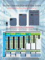
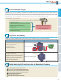
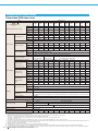
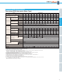
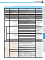
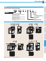
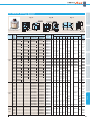
High Performance Inverter
New
F U J I E L E C T R I C I N V E RT E R S
The FRENIC-Ace Inverters are full feature drives offering great value
and maintain high performance through optimal design
for a wide range of applications for various machines and devices.
24A1-E-0042c
The Next Generation Of Inverters Have Arrived
IIntroducing
t d i O
Our N
New St
Standard
d d IInverter!
t !
Enjoy A Full Range Of Applications
The standard inverter for the next generation, the FRENIC-Ace, can be used
in most types of application—from fans and pumps to specialized machinery.
3-phase 400V series
Nominal
applied
motor
[kW]
0.1
0.2
0.4
0.75
1.1
1.5
2.2
3
3.7
5.5
7.5
11
15
18.5
22
30
37
45
55
75
90
110
132
160
200
220
250
280
315
Rating
condition
Application
ND rating
HD rating
Rated
output
current
Model
FRN0002E2 -4
2.1A
FRN0004E2 -4
FRN0006E2 -4
FRN0007E2 -4
4.1A
5.5A
6.9A
FRN0012E2 -4
12A
FRN0022E2
FRN0029E2
FRN0037E2
FRN0044E2
FRN0059E2
FRN0072E2
FRN0085E2
FRN0105E2
FRN0139E2
FRN0168E2
FRN0203E2
FRN0240E2
FRN0290E2
FRN0361E2
FRN0415E2
-4
-4
-4
-4
-4
-4
-4
-4
-4
-4
-4
-4
-4
-4
-4
21.5A
28.5A
37A
44A
59A
72A
85A
105A
139A
168A
203A
240A
290A
361A
415A
FRN0520E2 -4
FRN0590E2 -4
520A
590A
Overload current rating Max. ambient temp.
120% -1min
40C
Rated
output
current
Model
HHD rating
Rated
output
current
Model
FRN0002E2 -4
FRN0004E2 -4
1.8A
3.4A
FRN0002E2 -4
FRN0004E2 -4
1.8A
3.4A
FRN0006E2 -4
FRN0007E2 -4
5A
6.3A
FRN0006E2 -4
FRN0007E2 -4
5A
6.3A
FRN0012E2
FRN0022E2
FRN0029E2
FRN0037E2
FRN0044E2
FRN0059E2
FRN0072E2
FRN0085E2
FRN0105E2
FRN0139E2
FRN0168E2
FRN0203E2
FRN0240E2
FRN0290E2
FRN0361E2
FRN0415E2
FRN0520E2
FRN0590E2
11.1A
17.5A
23A
31A
38A
45A
60A
75A
91A
112A
150A
176A
210A
253A
304A
377A
415A
477A
FRN0012E2
FRN0022E2
FRN0029E2
FRN0037E2
FRN0044E2
FRN0059E2
FRN0072E2
FRN0085E2
FRN0105E2
FRN0139E2
FRN0168E2
FRN0203E2
FRN0240E2
FRN0290E2
FRN0361E2
FRN0415E2
FRN0520E2
-4
-4
-4
-4
-4
-4
-4
-4
-4
-4
-4
-4
-4
-4
-4
-4
-4
11.1A
17.5A
23A
31A
38A
45A
60A
75A
91A
112A
150A
176A
210A
253A
304A
377A
415A
FRN0590E2 -4
520A
-4
-4
-4
-4
-4
-4
-4
-4
-4
-4
-4
-4
-4
-4
-4
-4
-4
-4
Overload current rating Max. ambient temp.
150% -1min
40C
Overload current rating Max. ambient temp.
120% -1min
50C
HND rating
Rated
output
current
Model
FRN0002E2 -4
FRN0004E2 -4
1.5A
2.5A
FRN0006E2 -4
FRN0007E2 -4
4.2A
5.5A
FRN0012E2
FRN0022E2
FRN0029E2
FRN0037E2
FRN0044E2
FRN0059E2
FRN0072E2
FRN0085E2
FRN0105E2
FRN0139E2
FRN0168E2
FRN0203E2
FRN0240E2
FRN0290E2
FRN0361E2
FRN0415E2
FRN0520E2
FRN0590E2
9A
13A
18A
24A
30A
39A
45A
60A
75A
91A
112A
150A
176A
210A
253A
304A
377A
415A
-4
-4
-4
-4
-4
-4
-4
-4
-4
-4
-4
-4
-4
-4
-4
-4
-4
-4
Overload current rating Max. ambient temp.
150% -1min,
50C
200% -0.5sec
Model
Rated
output
current
FRN0001E2S-2
FRN0002E2S-2
FRN0004E2S-2
FRN0006E2S-2
1.3A
2A
3.5A
6A
FRN0010E2S-2
FRN0012E2S-2
9.6A
12A
FRN0020E2S-2
FRN0030E2S-2
FRN0040E2S-2
FRN0056E2S-2
FRN0069E2S-2
FRN0088E2S-2
FRN0115E2S-2
19.6A
30A
40A
56A
69A
88A
115A
Model
HHD rating
Rated
output
current
Model
Rated
output
current
FRN0001E2S-2
FRN0002E2S-2
FRN0004E2S-2
FRN0006E2S-2
0.8A
1.6A
3A
5A
FRN0001E2S-7
FRN0002E2S-7
FRN0003E2S-7
FRN0005E2S-7
0.8A
1.6A
3A
5A
FRN0010E2S-2
FRN0012E2S-2
8A
11A
FRN0008E2S-7
FRN0011E2S-7
8A
11A
FRN0020E2S-2
FRN0030E2S-2
FRN0040E2S-2
FRN0056E2S-2
FRN0069E2S-2
FRN0088E2S-2
FRN0115E2S-2
17.5A
25A
33A
47A
60A
76A
90A
Overload current rating Max. ambient temp.
150% -1min,
50C
200% -0.5sec
Overload current rating Max. ambient temp.
150% -1min,
50C
200% -0.5sec
Vertical conveyance
Vertical conveyance
Vertical conveyance
Winding machines
Winding machines
Winding machines
Printing machines
Printing machines
Printing machines
Overload current rating Max. ambient temp.
120% -1min
50C
Fans, pumps
Fans, pumps
Fans, pumps
Wire drawing
Wire drawing
Vertical conveyance
1-phase 200V series
HHD rating
Wire drawing
*3-phase 200V series supports only a product for Asia.
2
3-phase 200V series
HND rating
F U J I E L E C T R I C I N V E RT E R S
Major Functions
Customizable Logic
Standard Model Specifications
Customizable logic function is available as a standard feature. FRENIC-Ace has built-in customizable logic functions with a maximum of
200 steps including both digital and analog operation functions, giving customers the ability to customize their inverters—from simple
logic functions to full-scale programming. Fuji Electric also has plans to offer programming templates for wire drawing machines, hoists,
spinning machines, and other applications so that the FRENIC-Ace can be used as a dedicated purpose inverter.
Example: Hoist crane application
Programming the FRENIC-Ace main unit with the required logic for controlling a hoist
(1) Set speed program
(2) Reset the alarm by using the push-button switch
(3) Mechanical limit switch function
(4) Detect load
(5) Automatic speed drive when no load is detected
Common Specifications
Dedicated/specialized functions for
hoist application implemented by
using customizable logic
(6) Overload stop function
Basic Wiring Diagram
Superior Flexibility
FRENIC-Ace has readily available interface cards and various types of fieldbus / network to maximize its flexibility.
Option
Installation type
RS485 communications card
PG interface (5V) card
PG interface (12/15V) card
Terminal Functions
RJ-45 connector
Optional control terminal block
Control terminal block
Front face panel
External Dimensions
DeviceNet communication card
CC-Link communication card
PROFIBUS-DP communication card (Coming Soon)
EtherNet/IP communication card (Coming Soon)
ProfiNet-RT communication card (Coming Soon)
CANopen communication card (Coming Soon)
Digital input/output interface card
Analog input/output interface card
Optional front face keypad mount
30kW(ND): option card is built-in
Options
Wide Variety Of Functions As A Standard Feature
Sensorless dynamic torque vector control
Motor vector control with PG (with optional card)
Synchronous motor with sensorless vector control
2-channel on-board RS485 communications port
Standard CANopen compatibility
Removable keypad device
Removable control terminal block board
3
Multi-Function Keypad (option)
FRENIC-Ace has two different multi-function keypads available
Multi-function keypad with LCD display: Enhanced HMI functionality
USB keypad: Connect to a computer for more efficient operation (set-up, troubleshooting, maintenance, etc)
LAN cable
USB–USBminiB cable
USB keypad
Multi-function keypad
with LCD screen
Functional Safety
FRENIC-Ace is equipped with STO functional safety function as a standard. Therefore output circuit magnetic contactors are not required
for safe stop implementation. Enhanced standard features position FRENIC-Ace ahead of its class (Safety input: 2CH, output: 1CH).
Complies with (coming soon)
EN ISO 13849-1: 2008, Cat.3 / PL=e
IEC/EN 61800-5-2: 2007 SIL3 (Safety feature: STO)
IEC/EN 60204-1: 2005/2006 Stop category 0
IEC/EN 62061: 2005 SIL3
IEC/EN 61508-1 to -7: 2010 SIL3
10 Years Lifetime Design
FRENIC-Ace components have a design life of ten years.
A longer maintenance cycle also helps to reduce running costs.
Main circuit capacitor
10 years*
Electrolytic capacitors on PCB
10 years*
Cooling fan
Design life
10 years*
Ambient temperature
+40°C
Load rate
100% (HHD specifications)
80% (HND/HD/ND specifications)
Life conditions
* ND specifications have a rated current of two sizes higher than HHD specifications, so the life is 7 years.
Standards
RoHS Directive
Global Compliance
Standard compliance
Standard compliance with European regulations that limit the use of specific hazardous substances (RoHS)
<Six hazardous Lead, mercury, cadmium, hexavalent chromium, polybrominated biphenyl
substances> (PBB), polybrominated biphenyl ether (PBDE)
<About RoHS>
Directive 2002/95/EC, issued by the European Parliament and European
Council, limits the use of specific hazardous substances in electrical and electronic devices.
4
EC Directives (CE Mark)
UL Standard (cUL Certified)
F U J I E L E C T R I C I N V E RT E R S
Major Functions
Standard Model Specifications
Three phase 400V class series
Specifications
E2S-4A),
0006
0007
0012
ND
0.75
1.5
2.2
3.0
HD
0.75
1.1
2.2
3.0
HND
0.75
1.1
2.2
3.0 *11
5.5 *11
HHD
0.4
0.75
1.5
2.2
3.7
ND
1.6
3.1
4.2
5.3
9.1
HD
1.4
2.6
3.8
4.8
HND
1.4
2.6
3.8
4.8 *11
HHD
1.1
1.9
3.2
4.2
Rated voltage [V] *3
Output ratings
Rated current [A] *4
Overload capability
0022
0029
0037
0044
0059
5.5
11
15
5.5
7.5
11
7.5
5.5
16
8.5
8.5 *11
18.5
22
30
37
15
18.5
22
30
11
15
18.5
22
30
7.5
11
15
18.5
22
22
28
34
45
55
13
18
24
29
34
46
13
18
24
29
34
46
6.9
9.9
14
18
23
30
34
Three-phase 380 to 480V (With AVR)
ND
2.1
4.1
5.5
6.9
12
21.5
28.5
37.0
44.0
59.0
72.0
HD
1.8
3.4
5.0
6.3
11.1
17.5
23.0
31.0
38.0
45.0
60.0
HND
1.8
3.4
5.0
6.3*11
11.1*11
17.5
23.0
31.0
38.0
45.0
60.0
HHD
1.5
2.5
4.2
5.5
9.0
13.0
18.0
24.0
30.0
39.0
45.0
ND, HND
120% of nominal current for 1min
HD
150% of nominal current for 1min
HHD
150% of nominal current for 1min or 200% of nominal current for 0.5s
Main power supply
Three-phase 380 to 480V (With AVR)
Voltage/frequency variations
Voltage: +10 to -15% (Voltage unbalance:2% or less *8, Frequency: +5 to -5%)
ND
2.7
4.8
7.3
11.3
16.8
33.0
43.8
52.3
60.6
77.9
94.3
Rated current
HD
2.7
3.9
7.3
11.3
16.8
23.2
33.0
43.8
52.3
60.6
77.9
without DCR *5 [A]
HND
2.7
3.9
7.3
11.3*11
16.8 *11
23.2
33.0
43.8
52.3
60.6
77.9
HHD
1.7
3.1
5.9
8.2
13.0
17.3
23.2
33.0
43.8
52.3
60.6
ND
1.5
2.9
4.2
5.8
10.1
21.1
28.8
35.5
42.2
57.0
68.5
Rated current
HD
1.5
2.1
4.2
5.8
10.1
14.4
21.1
28.8
35.5
42.2
57.0
with DCR *5 [A]
HND
1.5
2.1
4.2
5.8 *11
10.1*11
14.4
21.1
28.8
35.5
42.2
57.0
HHD
0.85
1.6
3.0
4.4
7.3
10.6
14.4
21.1
28.8
35.5
42.2
Input ratings
Required power
supply capacity *6
[kVA]
Braking torque *7 [%]
Braking
ND
1.1
2.1
3.0
4.1
7.0
15
20
25
29
39
47
HD
1.1
1.5
3.0
4.1
7.0
10
15
20
25
29
39
HND
1.1
1.5
3.0
4.1*11
7.0 *11
10
15
20
25
29
39
HHD
0.6
1.2
2.1
3.1
5.1
7.3
10
15
20
25
29
ND
53%
50%
48%
29%
27%
12%
HD
53%
68%
48%
29%
27%
15%
HND
53%
68%
48%
29%*11
27%*11
HHD
100%
70%
40%
Braking level: 0 to 60% (ND spec.), 0 to 80% (HD/HND spec.), 0 to 100% (HHD spec.) of nominal current
Braking chopper
Built-in
Braking resistor
Option
EMC filter *9
DC reactor (DCR)
15%
20%
Starting frequency: 0.0 to 60.0Hz, Braking time: 0.0 to 30.0s,
DC braking
*1
*2
*3
*4
0072
Common Specifications
Rated capacity [kVA] *2
0004
Basic Wiring Diagram
Nominal applied motor *1 [kW]
0002
(0002~0012)*12)
Terminal Functions
E2S-G
External Dimensions
E2S-K(0022~)), (FRN
Compliant with EMC Directives, Emission and Immunity: Category C3 (2nd Env.) (EN61800-3:2004)
ND
Option
HND, HD
Option
HHD
Option
Enclosure (IEC60529)
IP20, UL open type
Cooling method
Natural cooling
Mass (Basic Type (EMC Filter Built-in Type)) [kg]
1.2
1.5
Options
(FRN
-4E) *10, (FRN
E2
Standard Model Specifications
Items
Type (FRN
Fan cooling
1.5
Fuji 4-pole standard motor
Rated capacity is calculated by assuming the output rated voltage as 440 V.
Output voltage cannot exceed the power supply voltage.
When the carrier frequency (F26) is set to below value or higher, the inverter is sure to
be necessary to derate their nominal current.
HHD spec.---type 0002 to 0012 : 8kHz, type 0022 to 0168 : 10kHz,
type 0203 to 0590 : 6kHz
HND spec.---type 0002 to 0012 : 8kHz, type 0022 to 0059 : 10kHz,
type 0072 to 0168 : 6kHz, type 0203 to 0590 : 4kHz
HD,ND spec.---All type : 4kHz
The rated output current at HD/ND spec. is decreased 2% for every 1 °C (1.8 °F) when
ambient temperature is +40 °C (+104 °F) or more.
*5 The value is calculated assuming that the inverter is connected with a power supply with
the capacity of 500 kVA
(or 10 times the inverter capacity if the inverter capacity exceeds 50 kVA) and %X is 5%.
Be sure to use the DCR when applicable motor capacity is 75kW or above.
1.6
1.9
5.0(TBD) 5.0(TBD) 8.0(TBD) 9.0(TBD) 9.5(10.5)
10(11.2)
*6 Obtained when a DC reactor (DCR) is used.
*7 Average braking torque for the motor running alone. (It varies with the efficiency of
the motor.)
*8 Voltage unbalance (%) =(Max. voltage (V) - Min. voltage (V))/Three -phase average
voltage (V) × 67 (IEC 61800 - 3) If this value is 2 to 3%, use an optional AC reactor
(ACR).
*9 The EMC Filter Built-in Type supports only a product for EU.
*10
: S: Standard (basic type), E: EMC filter built-in type (0059 to 0590)
*11 HND spec. of the type 0007 and 0012: allowable ambient temperature 40 °C (+104 °F)
or less.
The rated output current at HND spec. is decreased 1% for every 1 °C (1.8 °F) when
ambient temperature is +40 °C (+104 °F) or more.
*12
: A: 1 CAN terminal, 1 analog current output
B: NONE CAN terminal, 2 analog current output
5
Standard Model Specifications
Three phase 400V class series
Items
Type (FRN
E2
(FRN
Specifications
-4E) *11
Nominal applied motor *1 [kW]
Rated capacity [kVA] *2
Overload capability
0168
0203
0240
0290
0361
55
75
90
110
132
160
200
220
280
315
45
55
75
90
110
132
160
200
220
250
HND
37
45
55
75
90
110
132
160
200
220
280
HHD
30
37
45
55
75
90
110
132
160
200
220
ND
65
80
106
128
155
183
221
275
316
396
450
HD
57
69
85
114
134
160
193
232
287
316
364
HND
57
69
85
114
134
160
193
232
287
316
396
46
57
69
85
114
134
160
193
232
287
316
590
Three-phase 380 to 480V (With AVR)
ND
85.0
105
139
168
203
240
290
361
415
520
HD
75.0
91.0
112
150
176
210
253
304
377
415
477
HND
75.0
91.0
112
150
176
210
253
304
377
415
520
HHD
60.0
75.0
91.0
112
150
176
210
253
304
377
415
ND, HND
120% of nominal current for 1min
HD
150% of nominal current for 1min
HHD
150% of nominal current for 1min or 200% of nominal current for 0.5s
Three-phase 380 to 480V, 60Hz*9
480V, 50/60Hz
Voltage: +10 to -15% (Voltage unbalance:2% or less *8, Frequency: +5 to -5%)
ND
114
140
-
-
-
-
-
-
-
-
-
Rated current
HD
94.3
114
140
-
-
-
-
-
-
-
-
without DCR *5 [A]
HND
94.3
114
140
-
-
-
-
-
-
-
-
HHD
77.9
94.3
114
140
-
-
-
-
-
-
-
ND
83.2
102
138
164
201
238
286
357
390
500
559
Rated current
HD
68.5
83.2
102
138
164
201
238
286
357
390
443
with DCR *5 [A]
HND
68.5
83.2
102
138
164
201
238
286
357
390
500
HHD
57.0
68.5
83.2
102
138
164
201
238
286
357
390
Input ratings
Required power
supply capacity *6
[kVA]
Braking torque *7 [%]
Braking
ND
58
71
96
114
139
165
199
248
271
347
388
HD
47
58
71
96
114
140
165
199
248
271
307
HND
47
58
71
96
114
140
165
199
248
271
347
HHD
39
47
58
71
96
114
140
165
199
248
271
ND
5 to 9%
HD
7 to 12%
HND
7 to 12%
HHD
10 to 15%
Starting frequency: 0.0 to 60.0Hz, Braking time: 0.0 to 30.0s,
DC braking
Braking level: 0 to 60% (ND spec.), 0 to 80% (HD/HND spec.), 0 to 100% (HHD spec.) of nominal current
Braking chopper
Option
Braking resistor
Option
EMC filter *10
Compliant with EMC Directives, Emission and Immunity: Category C3 (2nd Env.) (EN61800-3:2004)
ND
DC reactor (DCR)
Enclosure (IEC60529)
Cooling method
Mass (Basic Type (EMC Filter Built-in Type)) [kg]
Attached as standard
Option
Attached as standard
Option
HND, HD
Attached as standard
Option
HHD
6
Three-phase 380 to 440V, 50Hz
Three-phase 380 to Three-phase 380 to
480V (With AVR)
*6
*7
*8
*9
*10
*11
0590
37
Voltage/frequency variations
*5
0520
45
Main power supply
*1
*2
*3
*4
0415
HD
HHD
Rated current [A] *4
0139
ND
Rated voltage [V] *3
Output ratings
0105
0085
E2S-4A)
IP00, UL open type
Fan cooling
25(26)
26(27)
30(31)
33(33)
40(40)
62(62)
63(63)
95(95)
96(96)
130(130) 140(140)
Fuji 4-pole standard motor
Rated capacity is calculated by assuming the output rated voltage as 440 V.
Output voltage cannot exceed the power supply voltage.
When the carrier frequency (F26) is set to below value or higher, the inverter is sure to be necessary to derate their nominal current.
HHD spec.---type 0002 to 0012 : 8kHz, type 0022 to 0168 : 10kHz, type 0203 to 0590 : 6kHz
HND spec.---type 0002 to 0012 : 8kHz, type 0022 to 0059 : 10kHz, type 0072 to 0168 : 6kHz, type 0203 to 0590 : 4kHz
HD,ND spec.---All type : 4kHz
The rated output current at HD/ND spec. is decreased 2% for every 1 °C (1.8 °F) when ambient temperature is +40 °C (+104 °F) or more.
The value is calculated assuming that the inverter is connected with a power supply with the capacity of 500 kVA (or 10 times the inverter capacity if the inverter capacity exceeds 50 kVA) and %X is 5%.
Be sure to use the DCR when applicable motor capacity is 75kW or above.
Obtained when a DC reactor (DCR) is used.
Average braking torque for the motor running alone. (It varies with the efficiency of the motor.)
Voltage unbalance (%) =(Max. voltage (V) - Min. voltage (V))/Three -phase average voltage (V) × 67 (IEC 61800 - 3) If this value is 2 to 3%, use an optional AC reactor (ACR).
The 400 V class series with type 0203 or above is equipped with a set of switching connectors (male) which should be configured according to the power source voltage and frequency.
The EMC Filter Built-in Type supports only a product for EU.
: S: Standard (basic type), E: EMC filter built-in type (0059 to 0590)
F U J I E L E C T R I C I N V E RT E R S
Major Functions
Standard Model Specifications
Three phase 200V class series (Basic Type)
Specifications
E2S-2G (0001~0020))*11
0001
0002
0004
0006
0010
0012
0020
0030
0040
0056
0069
0088
0115
HND
0.2
0.4
0.75
1.1
2.2
3.0 *11
5.5 *11
7.5
11
15
18.5
22
30
HHD
0.1
0.2
0.4
0.75
1.5
2.2
3.7
5.5
7.5
11
15
18.5
22
HND
0.5
0.8
1.3
2.3
3.7
4.6 *11
7.5 *11
11
15
21
26
34
44
HHD
0.3
0.6
1.1
1.9
3.0
4.2
6.7
9.5
13
18
23
29
34
Rated capacity [kVA] *2
Three-phase 200 to 240V (With AVR)
Rated voltage [V] *3
Output ratings
Rated current [A] *4
Overload capability
HND
1.3
2.0
3.5
6.0
9.6
12*11
19.6 *11
30
40
56
69
88
115
HHD
0.8
1.6
3.0
5.0
8.0
11
17.5
25
33
47
60
76
90
HND
120% of nominal current for 1min
HHD
150% of nominal current for 1min or 200% of nominal current for 0.5s
Main power supply
Three-phase 200 to 240V, 50/60Hz
Voltage/frequency variations
HND
1.8
2.6
4.9
6.7
12.8
17.9 *11
31.9 *11
42.7
60.7
80.0
97.0
112
151
without DCR *5 [A]
HHD
1.1
1.8
3.1
5.3
9.5
13.2
22.2
31.5
42.7
60.7
80.0
97.0
112
Rated current
HND
0.93
1.6
3.0
4.3
8.3
11.7*11
19.9 *11
28.8
42.2
57.6
71.0
84.4
114
with DCR *5 [A]
HHD
0.57
0.93
1.6
3.0
5.7
8.3
14.0
21.1
28.8
42.2
57.6
71.0
84.4
Required power
HND
0.4
0.6
1.1
1.5
2.9
4.1*11
6.9 *11
10
15
20
25
30
40
supply capacity *6 [kVA]
HHD
0.2
0.4
0.6
1.1
2.0
2.9
4.9
7.3
10
15
20
25
30
HND
75%
53%
68%
48%
150%
100%
Input ratings
Braking torque *7 [%]
Braking
Voltage: +10 to -15% (Voltage unbalance:2% or less *8, Frequency: +5 to -5%)
Rated current
HHD
70%
29%*11 27%*11
40%
Common Specifications
Nominal applied motor *1 [kW]
15%
Basic Wiring Diagram
E2S-2A(0030~)) *9, (FRN
Standard Model Specifications
Items
Type (FRN
20%
Starting frequency: 0.0 to 60.0Hz, Braking time: 0.0 to 30.0s,
DC braking
Braking level: 0 to 60% (ND spec.), 0 to 80% (HD/HND spec.), 0 to 100% (HHD spec.) of nominal current
Built-in
Braking chopper
Option
DC reactor (DCR)
Enclosure (IEC60529)
HND
Option
HHD
Option
IP20, UL open type
Cooling method
Naturalural cool
Mass [kg]
0.5
*6
*7
*8
*9
*10
*11
0.8
1.5
1.5
1.8
5.0
5.0
8.0
9.0
9.5
10
Fuji 4-pole standard motor
Rated capacity is calculated by assuming the output rated voltage as 220 V.
Output voltage cannot exceed the power supply voltage.
When the carrier frequency (F26) is set to below value or higher, the inverter is sure to be necessary to derate their nominal current.
HHD spec.---type 0001 to 0020 : 8kHz, type 0030 to 0115 : 10kHz,
HND spec.---type 0001 to 0020 : 4kHz, type 0030 to 0069 : 10kHz, type 0088,0115 : 4kHz
The value is calculated assuming that the inverter is connected with a power supply with the capacity of 500 kVA
(or 10 times the inverter capacity if the inverter capacity exceeds 50 kVA) and %X is 5%.
Obtained when a DC reactor (DCR) is used.
Average braking torque for the motor running alone. (It varies with the efficiency of the motor.)
Voltage unbalance (%) =(Max. voltage (V) - Min. voltage (V))/Three -phase average voltage (V) × 67 (IEC 61800 - 3)
If this value is 2 to 3%, use an optional AC reactor (ACR).
Three phase 200V class series supports only a product for Asia
HND spec. of the type 0012 and 0020: allowable ambient temperature 40 °C (+104 °F) or less.
The rated output current at HND spec. is decreased 1% for every 1 °C (1.8 °F) when ambient temperature is +40 °C (+104 °F) or more.
: A: 1 CAN terminal, 1 analog current output
B: NONE CAN terminal, 2 analog current output
External Dimensions
*5
Fan cooling
0.6
Options
*1
*2
*3
*4
0.5
Terminal Functions
Braking resistor
7
Common Specifications
Specifications
Items
Maximum frequency
Base frequency
Starting frequency
Output
Carrier frequency
Output frequency
accuracy (Stability)
Frequency setting
resolution
Speed control range
Speed control
accuracy
Control method
Voltage/Frequency
characteristic
- HHD/HND/HD spec.: 25 to 500 Hz variable
(V/f control mode, Magnetic pole position sensorless vector control mode)
(Up to 200 Hz under vector control with speed sensor)
- ND spec.: 25 to 120 Hz variable (all control mode)
25 to 500 Hz variable (in conjunction with the maximum frequency)
0.1 to 60.0 Hz variable
(0.0 Hz under vector control with speed sensor)
- Analog setting: ±0.2% of maximum frequency 25±10°C
- Keypad setting: ±0.01% of maximum frequency -10 to +50°C
- Analog setting: 0.05% of maximum frequency
- Keypad setting: 0.01 Hz (99.99 Hz or less), 0.1 Hz (100.0 to 500.0 Hz)
- Link setting: 0.005% of maximum frequency or 0.01 Hz (fixed)
- 1 : 1500 (Minimum speed : Nominal speed, 4-pole, 1 to 1500 rpm)
- 1 : 100 (Minimum speed : Nominal speed, 4-pole, 15 to 1500 rpm)
- 1 : 10 (Minimum speed : Nominal speed, 6-pole, 180 to 1800 rpm)
- Analog setting: ±0.2% of maximum frequency or below 25 ±10°C
- Digital setting: ±0.01% of maximum frequency or below -10 to +50°C
- Analog setting: ±0.5% of base frequency or below 25 ±10°C
- Digital setting: ±0.5% of base frequency or below -10 to +50°C
- V/f control
- Speed sensor less vector control (Dynamic torque vector control)
- V/f control with slip compensation active
- V/f control with speed sensor (The PG option card is required.)
- V/f Control with speed sensor (+Auto Torque Boost) (The PG option card is required.)
- Vector control with speed sensor (The PG option card is required.)
- Vector control without magnetic pole position sensor
- Possible to set output voltage at base frequency and at maximum output frequency (160 to 500 V).
- Non-linear V/f setting (3 points): Free voltage (0 to 500 V) and frequency (0 to 500 Hz) can be set.
Starting torque
Three phase 400V class
- 200% or above (HHD spec.:type 0072 or below) / 150% or higher (HHD spec.:type 0085 or above) at reference
frequency 0.5Hz
- 120% or higher at reference frequency 0.5Hz, (HND/ND spec.)
- 150% or higher at reference frequency 0.5Hz, (HD spec.)
(Base frequency 50 Hz, with activating the slip compensation and the auto torque boost mode, applied motor
is Fuji 4-pole standard motor.)
Three phase 200V class
- 200% or above (HHD spec.:type 0069 or below) at reference frequency 0.5Hz
- 120% or higher at reference frequency 0.5Hz, (HND spec.)
(Base frequency 50 Hz, with activating the slip compensation and the auto torque boost mode, applied motor
is Fuji 4-pole standard motor.)
Control
- Auto torque boost (For constant torque load)
- Manual torque boost: Torque boost value can be set between 0.0 and 20.0%.
- Select application load with the function code. (Variable torque load or constant torque load)
- Keypad:
Start and stop with
and
keys (Standard keypad)
- External signals (digital inputs): Forward (Reverse) rotation, stop command (capable of 3-wire operation),
coast-to-stop command, external alarm, alarm reset, etc.
- Link operation: Operation via built-in RS-485 or field bus (option) communications
- Switching operation command: Remote/local switching, link switching
8
IMPG-VC
IMPG-VC
Three phase 400V class
- Type 0002 to 0059:
- 0.75 to 16kHz variable (HHD/HND/HD spec.)
- 0.75 to 10kHz variable (ND spec.)
- Type 0072 to 0168:
- 0.75 to 16kHz variable (HHD spec.)
- 0.75 to 10kHz variable (HND/HD spec.)
- 0.75 to 6kHz variable (ND spec.)
- Type 0203 or above type of capacity:
- 0.75 to 10kHz variable (HHD spec.)
- 0.75 to 6kHz variable (HND/HD/ND spec.)
Three phase 200V class
- Type 0030,0040,0056,0069
- 0.75 to 16kHz variable (HHD/HND/ spec.)
Note: Carrier frequency drops automatically to protect the inverter depending on environmental temperature and
output current. (This auto drop function can be canceled.)
Torque boost
Start/Stop operation
Remarks
IMPG-VC
IMPG-VF
PM-SVC
IMPG-VC
PM-SVC
VF
IM-SVC(DTV)
VF with SC
IMPG-VF
IMPG-ATB
IMPG-VC
PM-SVC
F U J I E L E C T R I C I N V E RT E R S
Items
Specifications
and
Remarks
keys
- External volume: Available to be set with external frequency command potentiometer. (1 to 5 k 1/2 W)
- Analog input: 0 to ±10 V DC (±5 V DC)/ 0 to ±100% (terminal [12])
0 to +10 V DC (+5 V DC)/ 0 to +100% (terminal [12])
+4 to +20 mA DC/ 0 to 100% (terminal [C1])
+4 to +20 mA DC/ -100 to 0 to 100% (terminal [C1])
0 to +20 mA DC/ 0 to 100% (terminal [C1])
0 to +20 mA DC/ -100 to 0 to 100% (terminal [C1])
0 to +10 V DC (+5 V DC)/ 0 to +100% (terminal [V2])
0 to +10 V DC (+5 V DC)/ -100 to 0 to +100% (terminal [V2])
- UP/DOWN operation: Frequency can be increased or decreased while the digital input signal is ON.
- Multi-step frequency: Selectable from 16 different frequencies (step 0 to 15)
Analog input
between
DC+1 to +5V
is available
with analog
bias/gain
function for
input.
Standard Model Specifications
- Keypad: Settable with
Major Functions
Common Specifications
- Pattern Operation Mode: Automatically run in accordance with the previously configured running time,rotation
direction, acceleration/deceleration and reference frequency. Maximum allowable settings are 7 stages.
- Link operation: Can be specified via built-in RS-485 or Can be specified via bus communicatons. (Option)
Common Specifications
Frequency setting
- Switching frequency setting source: Two of frequency settings source can be switched with an external
signal(digital input).
Remote/local switching,
Link switching
- Auxiliary frequency setting: Inputs at terminals [12], [C1] or [V2] can be added to the main setting as auxiliary
frequency settings.
Basic Wiring Diagram
- Operation at a specified ratio: The ratio can be set by analog input signal.
Inverse operation : Switchable from "0 to +10 VDC/0 to 100%" to "+10 to 0 VDC/0 to 100%"
by external command. (terminals [12]/[V2])
: Switchable from "0 to -10 VDC/0 to -100%" to "-10 to 0 VDC/0 to -100%"
by external command.(terminal [12])
: Switchable from "4 to +20 mA DC/0 to 100%" to "+20 to 4 mA DC/0 to 100%"
by external command.(terminal [C1])
: Switchable from "0 to +20 mA DC/0 to 100%" to "+20 to 4 mA DC/0 to 100%"
by external command.(terminal [C1])
Control
- Pulse train input (standard):
Pulse input = Terminal [X5], Rotational direction = Another input terminal except [X5].
Complementary output: Max. 100 kHz, Open collector output: Max. 30 kHz
Frequency limiter
(Upper limit and lower
limit frequencies)
- Specifies the upper and lower limits in Hz.
- Selectable for the operation performed when the reference frequency drops below the lower limit specified by
related function code.
Bias for frequency/
PID command
- Bias of set frequency and PID command can be independently set(setting range: 0 to ±100%).
Analog input
- Gain : Set in the range from 0 to 200%
- Off-set : Set in the range from -5.0 to +5.0%
- Filter : Set in the range from 0.00s to 5.00 s
- Polarity : Select from ± or +
Jump frequency
Timer operation
- Three operation points and their common jump width (0.0 to 30.0 Hz) can be set.
- Operate and stop by the time set with keypad. (1 cycle operation)
- Operation with
key (standard keypad),
or
External Dimensions
Acceleration/
Deceleration time
- Setting range: From 0.00 to 6000 s
- Switching: The four types of acceleration/deceleration time can be set or selected individually (switchable
during operation).
- Acceleration/deceleration pattern: Linear acceleration/deceleration, S-shape acceleration/deceleration (weak,
free (set by function codes)), curvilinear acceleration/deceleration
- Deceleration mode (coast-to-stop):Shut-off of the run command makes the motor coast to a stop.
- ACC./DEC. time for "Jogging operation" can be set. (0.00 to 6000s)
- Deceleration time for forcible stop: Deceleration stop by the forcible stop (STOP).
S-curve will be canceled during "Force to Stop".
Terminal Functions
- Pulse train input (option):The PG option card is required.
CW/CCW pulse, pulse + rotational direction
Complementary output: Max. 100 kHz, Open collector output: Max. 30 kHz
key (multi-functional keypad), or digital contact input
Options
Jogging operation
FWD or REV.(Exclusive acceleration/deceleration time setting, exclusive frequency setting)
Auto-restart after
momentary power
failure
(Trip at power failure) The inverter trips immediately after power failure.
(Trip at power recovery) Coast-to-stop at power failure and trip at power recovery
(Deceleration stop) Deceleration stop at power failure, and trip after stoppage
(Continue to run) Operation is continued using the load inertia energy.
(Start at the frequency selected Coast-to-stop at power
before momentary power failure) failure and start after power recovery at the frequency selected before momentary stop.
9
Common Specications
Items
Specications
Remarks
Coast-to-stop at power failure and start at the starting
(Start at starting frequency)
frequency after power recovery.
(Start at the searched frequency)
Coast-to-stop at power failure and start at the serched
frequency after power recovery.
Hardware current limiter
- Limits the current by hardware to prevent an overcurrent trip caused by fast load variation or momentary power
failure, which cannot be covered by the software current limiter. This limiter can be canceled.
Control
Software current limiter - Automatically reduces the frequency so that the output current becomes lower than the preset operation level.
Operation by commercial
- With commercial power selection command, the inverter outputs 50/60 Hz (SW50,SW60).
power supply
Slip compensation
- Compensates the motor slip in order to keep their speed at the reference one regardless of their load torque.
- Adjustable compensation time constant is possible.
Droop control
- In a machine driven with multi-motor system, this function adjusts the speed of each motor individually to
balance their load torque.
Torque limiter
Control output torque or torque current so that output torque or torque current are preset limiting value or less.
(The torque current limit is only available in IMPG-VC or PM-SVC mode.)
- Switchable between 1st and 2nd torque limit values.
Torque current limiter
- "Torque limit" and "Torque current limit" are selectable.
- "Torque limit" or "Torque current limit" by analog input.
Overload stopping
- When detected torque or current exceed the preset value, inverter will decelerate and stop or will coast to stop
a motor.
PID Control
- PID processor for process control/dancer control
- Normal operation/inverse operation
- PID command: Keypad, analog input (from terminals [12], [C1] and [V2]), Multi-step setting(Selectable from 3
points), RS-485 communication
- PID feedback value (from terminals [12], [C1] and [V2])
- Alarm output (absolute value alarm, deviation alarm)
- Low liquid level stop function
- Anti-reset wind-up function
- PID output limiter
- Integration reset/hold
Auto-reset
- The auto-reset function that makes the inverter automatically attempt to reset the tripped state and restart
without issuing an alarm output (for any alarm) even if any protective function subject to reset is activated.
- The allowable maximum number of reset times for the inverter to automatically attempt to escape the tripped
state is 20.
Auto search for idling
motor speed
- The inverter automatically searches for the idling motor speed to start to drive without stopping. (Motor
constants must be needed tuning: Auto-tuning (ofine))
IMPG-VC
PM-SVC
- If the DC link bus voltage or calculated torque exceeds the automatic deceleration level
during deceleration, the inverter automatically prolongs the deceleration time to avoid
overvoltage trip. (It is possible to select forcible deceleration actuated when the deceleration time becomes
Automatic deceleration
three times longer.)
- If the calculated torque exceeds automatic deceleration level during constant speed operation, the inverter
avoids overvoltage trip by increasing the frequency.
Deceleration characteristic - The motor loss is increased during deceleration to reduce the regenerative energy in the inverter to avoid
(improved braking capacity) overvoltage trip.
Auto energy saving
operation
- The output voltage is controlled to minimize the total power loss of the motor and the inverter at a constant
speed.
Overload prevention
control
- If the ambient temperature or internal IGBT junction temperature is almost near the overheat level due to
overload, the inverter drops its output frequency automatically in order to escape overload situation.
Auto-tuning (off-line)
- Measures the motor parameters while the motor is stopped or running, for setting up motor parameters.
- Tuning mode to only identify %R1 and %X.
- Tuning mode to identify the parameters for PM motor.
Auto-tuning (on-line)
- Automatically adjusts motor parameters while the motor is driving in order to prevent the motor speed
uctuation caused by the temperature rise of the motor.
Cooling fan ON/OFF
control
- Detects inverter internal temperature and stops cooling fan when the temperature is low.
- the fan control signal can be output to an external device.
1st to 2nd motor
settings
- Switchable among the two motors.
It is possible to set the base frequency, rated current, torque boost, and electronic thermal slip compensation as
the data for 1st to 2nd motors.
Universal DI
The status of external digital signal connected with the universal digital input terminal is transferred to the host
controller.
Universal DO
Universal AO
Digital command signal from the host controller is output to the universal digital output terminal.
The analog command signal from the host controller is output to the analog output terminal.
Speed control
- Notch lter for vibration control (For IMPG-VC)
- Selectable among the four set of the auto speed regulator (ASR) parameters.
(The PG option card is required.)
Line speed control
In a machine such as winder/unwinder, regulates the motor speed to keep the peripheral speed of the roll
IMPG-VF
constant.
(The PG option card is required.)
IMPG-VC
PM-SVC
The positioning control starts from the preset start point and counts the feedback pulses from PG inside the Excluded
Positioning control with
inverter. The motor can be automatically started decelerating to the cleep speed which can be detected the IMPG-VC
pulse counter
PM-SVC
target position so that the motor can stop near the position.(The PG option card is required.)
10
F U J I E L E C T R I C I N V E RT E R S
Remarks
Enables synchronous operation of two motors equipped with a pulse generator(PG).(The PG option card is
required.)
Pre-excitation
Zero speed control
Servo lock
Excitation is carried out to create the motor ux before starting the motor.(The PG option card is required.)
The motor speed is held to zero by forcibly zeroing the speed command.(The PG option card is required.)
Stops the motor and holds the motor in the stopped position.(The PG option card is required.)
DC braking
When the run command turns OFF and the motor speed fall below the preset DC braking starting speed, the
inverter starts to inject DC current into the motor in order to stop the motor.
When the run command turns ON,the inverter starts to inject DC current into the motor in order to pre-excite.
Mechanical brake
control
- The inverter can output the signal which ON/OFF timing adjusted so that the mechanical brake can be turned in
Excluded
conjunction with detected current, torque, frequency, and release/apply delay timers.
PM-SVC
- Mechanical brake interlock input
Torque control
- Analog torque/torque current command input
- Speed limit function is provided to prevent the motor from becoming out of control.
- Torque bias (analog setting, digital setting)
Rotational direction
control
- Select either of reverse or forward rotation prevention.
Customizable logic
interface
The digital logic circuits and an analog arithmetic circuits can be chosen and connected with digital/analog
input/output signals.
The simple relay sequence which the customers demands can be constituted and made to calculate.
- Logic circuit
(Digital) AND, OR, XOR, ip-ops, rising/falling edge detection,counters, etc.
(Analog) Addition, subtraction, multiplication, division, limitter, absolute value, sign inversion addition,
comparison, highest selection, lowest selection, average value, measure conversion.
- Multifunctional timer
On-delay, off-delay, pulse train, etc.
Setting range: 0.0 to 600 s
- Input/output signal
terminal input / output, inverter control function
- Others
The 200 steps are available. Each step has 2 inputs and 1 output.
Standard Model Specications
IMPG-VC
IMPG-VC
IMPG-VC
IMPG-VC
Common Specications
Specications
Master-follower
operation
Basic Wiring Diagram
Control
Items
Major Functions
Common Specications
Running/Stopping
Speed monitor (reference frequency, output frequency, motor speed, load shaft speed, line speed, and speed
indication with percent), Output current in RMS[A], Output voltage in RMS[V], Calculated torque [%], Input power
[kW], PID command value, PID feedback value, PID output, Timer (Timer operation)[s], Load factor [%], Motor
output [kW]
Torque current [%] , Magnetic ux command [%], Analog input[%], Input watt hour [kWh]
Constant feeding rate time (set value) (min), Constant feeding rate time (running) (s)
Maintenance monitor
- Displays DC link bus voltage, Max. Output current in RMS, Input watt-hour, Input watt-hour data, Temperature
(inside the inverter and heat sink, Maximum value of each one), Capacitance of the DC link bus capacitor,
Lifetime of DC link bus capacitor (elapsed hours and remaining hours), Cumulative run time of power-ON time
counter of the inverter, electrolytic capacitors on the printed circuit boards, cooling fan and each motor,
Remaining time before the next motor maintenance, Remaining startup times before the next maintenance,
Number of startups (of each motor), Light alarm factors (Latest to 3rd last), Contents and numbers of RS-485
communications errors, Option error factors , Number of option errors ,ROM version of Inverter, Keypad and
Option port.
I/O checking
Trip mode
Light-alarm
Operating environment
Running or trip mode
Terminal Functions
Detachable with 7 segments LEDs (4 digits) , 7 keys(PRG/RESET,FUNC/DATA,UP,DOWN, RUN,STOP,SHIFT) and
6LED indicator (KEYPAD CONTROL,Hz,A,kW,×10,RUN)
External Dimensions
Display
Shows the status of the terminal Digital input/output, Relay out, Analog input/output.
Displays the cause of trip by codes.
Shows the light-alarm display l-al.
- Trip history: Saves and displays the cause of the last four trips (with a code).
- Saves and displays the detailed operation status data of the last four trips.
Installation location
Indoors
Ambient
Standard (Open Type)
-10 to +50°C (HHD/HND spec.)
-10 to +40°C (HD/ND spec.)
NEMA/UL Type 1
-10 to +40°C (HHD/HND spec.)
-10 to +30°C (HD/ND spec.)
Ambient humidity
5 to 95%RH (without condensation)
Atmosphere
Shall be free from corrosive gases, ammable gases, oil mist, dusts, vapor, water drops and direct sunlight.
(Pollution degree 2 (IEC60664-1))
The atmosphere must contain only a low level of salt. (0.01 mg/cm2 or less per year)
Options
Indicate
Applicable functions for
- Wire drawing machine
- Hoist
The specic functions which is suitable for each application eld are realized by customizable logics.
- Spinning machine
(Traverse)
11
Common Specifications
Items
Specifications
Remarks
1000m or lower
If the inverter is used in an altitude above 1000 m, you should apply an output current derating factor as listed in
below table.
Operating environment
Altitude
Output current derating factor
1.00
0.97
0.95
0.91
0.88
Altitude
1000m or lower
1000 to 1500m
1500 to 2000m
2000 to 2500m
2500 to 3000m
Three phase 400V class series
2 to less than 9Hz
9 to less than 20Hz
20 to less than 55Hz
55 to less than 200Hz
TYPE:0203 or below
3mm:(Max. amplitude)
9.8m/s 2
2m/s 2
1m/s 2
Three phase 200V class series
2 to less than 9Hz
9 to less than 20Hz
20 to less than 55Hz
55 to less than 200Hz
TYPE:0069 or below
3mm:(Max. amplitude)
9.8m/s 2
2m/s 2
1m/s 2
TYPE:0240 or above
3mm:(Max. amplitude)
2m/s 2
2m/s 2
1m/s 2
Storage environment
Vibration
Temperature
Relative humidity
Atmosphere
Atmospheric
pressure
-25 to +70°C (in transport)
Avoid such places where the inverter will be subjected to sudden changes in
-25 to +65°C (in storage)
temperature that will cause condensation to form.
5 to 95%RH
The inverter must not be exposed to dust, direct sunlight, corrosive or flammable gases, oil mist, vapor, water
drops or vibration. The atmosphere must contain only a low level of salt. (0.01 mg/cm2 or less per year)
86 to 106kPa (during storage)
70 to 106kPa (during transportation)
*Note : The meaning of the described abbreviations are shown as follows.
VF
V/f control
IM-SVC(DTV) Speed sensorless vector control (Dynamictorquevector control)
VF with SC
V/f control with slip compensation
IMPG-VF
V/f control with speed sensor (The PG option card is required.)
IMPG-ATB
V/f control with speed sensor (+Auto Torque Boost)(The PG option card is required.)
IMPG-VC
Vector control with speed sensor (The PG option card is required.)
PM-SVC
Magnetic pole position sensorless vector control
12
F U J I E L E C T R I C I N V E RT E R S
Major Functions
Basic Wiring Diagram
Standard Terminal Block Board Model
E2 - E
A
K
GA
Standard Model Specifications
FRN
In case of the motor with built-in cooling fan
Thermal relay
DBR (Option)
FU
FV
FM
FW
DBR (Option)
(G)
DCR (option) (*1)
MCCB
or
RCD/ELCB
Power supply
400V series
380V to 480V
200V series
200V to 240V
50/60Hz
DB
P
MC
P(+) DB
R
P(+)
2
1
N(-)
(THR)
Braking unit BU
(option)
(CM)
(THR)
N(-)
P(+)
Motor
Thermal relay
R
U
V
W
C
· Power voltage switching connector
"CN UX"
· Fan power connector
"CN R" / "CN W"
R0
T0
R1
T1
Auxiliary fan power supply
(G)
(CM)
DB
F
L1/R
L2/S
L3/T
Auxiliary control power supply
P
DB N(-)
P(+)
P1
2
1
2
1
(G)
U2 U1
DC/DC
Charge lamp
M
3~
PTC
Thermistor
TH1
THC
E
FAN NC
CN UX
G
Ground terminal
U
V
W
to [C1]
to [11]
Common Specifications
Transformer
CN R CN W
G
Ground terminal
RJ45 connector
+24VDC
30B
0V
30
Keypad
(Standard)
SW2
Communication port 1
(RS-485)
(EN2)
Contact outputs
30A
Option connector
(EN1)
Enable input
Alarm output
(for any fault)
Basic Wiring Diagram
30C
*2
(PLC)
SINK
Removable terminal block
SW1
<Y2>
Terminal Functions
(PLC)
Motor overload early warnig
SOURCE
<Y1>
Inverter running
Transistor output
(FWD)
<CMY>
(REV)
Run reverse command
Select multi-frequency(0 to 1 step)
(X1)
Digital input Select multi-frequency(0 to 3 step)
(X2)
Select multi-frequency(0 to 7 step)
(X3)
Coast to a stop
(X4)
Current output
FMI
(4 (0) to 20 mADC)
Voltage output
FMV
(0 to +10 VDC)
Pulse output
FMP
(25 to 32 kp/s)
(X5)
Reset alarm
Common terminal for
digital inputs
[FM]
Common terminal for
transistor outputs
(SINK/SOURCE)
Output frequency 1
Analog / pulse output
External Dimensions
Run forward command
SW5
(CM)
0V
[11]
Analog output common
+10VDC
[13]
Voltage input for setting 2
0 to +10VDC (0 to ±10VDC)
[12]
Common terminal for 1
analog inputs
[11]
DX+
DXCAN+
CAN-
Voltage input 12
(0 to +10 VDC)
(0 to ±10 VDC)
0V
Analog input
[C1]
(+)
Current/voltage input for setting
+4(0) to 20mADC / 0 to +10VDC
(-)
DBR: Dynamic Braking Resister
DCR: DC reactor
RCD: Residual-current-operated protective device
ELCB: Earth leakage circuit breaker
MC:
Magnetic contactor
MCCB: Molded case circuit braker
NOTE
AI
Current input C1
(4 (0) to 20 mADC)
PTC thermistor input
Voltage input V2
(0 to +10 VDC)
SW6
PTC
SW4
Communication port2
(RS-485)
(CAN-BUS)
RJ45 connector
V2
SW6
C1
SW3
0V
Options
Potentiometer power supply
3
*1 When connecting an optional DC reactor (DCR), remove the jumper bar from the terminals P1 and P(+).
The type 0139 (ND spec), 0168 (HD spec.) and higher types than 0203 are sure to connect the DCR (400V only).
Use a DCR when the capacity of the power supply transformer exceeds 500 kVA and is 10 times or more the
inverter rated capacity, or when there are thyristor-driven loads in the same power supply line.
*2 The default setting is “Source logic” for EU model.
This wiring diagram is to be used as a reference only when using standard terminal block model.
When wiring your inverter and/or before applying power, please always follow the connection diagrams
and the relevant information written in the User's Manual.
13
Basic Wiring Diagram
Standard Terminal Block Board Model
FRN
E2 - GB
In case of the standard terminal block type B
(without built-in CAN communication port and with dual Analog outputs)
In case of the motor with built-in cooling fan
Thermal relay
Transformer
DBR (Option)
FU
FV
FM
FW
DBR (Option)
(G)
DCR (option) (*1)
MCCB
or
RCD/ELCB
Power supply
400V series
380V to 480V
200V series
200V to 240V
50/60Hz
DB
P
MC
P(+) DB
R
P(+)
2
1
N(-)
(THR)
Braking unit BU
(option)
(CM)
(THR)
N(-)
P(+)
Motor
Thermal relay
R
· Power voltage switching connector
"CN UX"
· Fan power connector
"CN R" / "CN W"
R1
T1
U2 U1
DC/DC
Charge lamp
to [C1]
to [11]
M
3~
PTC
Thermistor
TH1
THC
E
FAN NC
CN UX
G
Ground terminal
U
V
W
U
V
W
C
R0
T0
Auxiliary fan power supply
(G)
(CM)
DB
F
L1/R
L2/S
L3/T
Auxiliary control power supply
P
DB N(-)
P(+)
P1
2
1
2
1
(G)
CN R CN W
G
Ground terminal
30C
RJ45 connector
+24VDC
30B
0V
30
Keypad
(Standard)
SW2
Communication port 1
(RS-485)
(EN2)
Contact outputs
Option connector
(EN1)
Enable input
Alarm output
(for any fault)
30A
*2
(PLC)
SINK
Removable terminal block
(PLC)
SW1
<Y2>
Motor overload early warnig
SOURCE
<Y1>
<CMY>
(REV)
Run reverse command
Select multi-frequency(0 to 1 step)
(X1)
Digital input Select multi-frequency(0 to 3 step)
(X2)
Select multi-frequency(0 to 7 step)
(X3)
Coast to a stop
(X4)
Current output
FMI
(4 (0) to 20 mADC)
Voltage output
FMV
(0 to +10 VDC)
Pulse output
FMP
(25 to 32 kp/s)
(X5)
Reset alarm
Common terminal for
digital inputs
3
Voltage input for setting 2
0 to +10VDC (0 to ±10VDC)
[13]
[12]
[11]
Analog output common
[C1]
(+)
Current/voltage input for setting
+4(0) to 20mADC / 0 to +10VDC
(-)
DBR: Dynamic Braking Resister
DCR: DC reactor
RCD: Residual-current-operated protective device
ELCB: Earth leakage circuit breaker
MC:
Magnetic contactor
MCCB: Molded case circuit braker
Analog / pulse output
Current output
FMI
(4 (0) to 20 mADC)
[FM2]
Voltage input 12
(0 to +10 VDC)
(0 to ±10 VDC)
[11]
Analog input
14
Output frequency 1
SW5
0V
Voltage output
(0~ +10VDC)
0V
Common terminal for 1
analog inputs
NOTE
[FM]
Common terminal for
transistor outputs
(SINK/SOURCE)
(CM)
+10VDC
Potentiometer power supply
Transistor output
Inverter running
(FWD)
Run forward command
AI
Current input C1
(4 (0) to 20 mADC)
PTC thermistor input
Voltage input V2
(0 to +10 VDC)
PTC
SW4
Output current
FMV
SW7
(*12)
0V
[11]
Analog output common
(*9)
V2
(DX+)
(DX-)
C1
SW3
0V
(SW6)
(*12)
Communication
port2
(RS-485)
(5D)
*1 When connecting an optional DC reactor (DCR), remove the jumper bar from the terminals P1 and P(+).
The type 0139 (ND spec), 0168 (HD spec.) and higher types than 0203 are sure to connect the DCR (400V only).
Use a DCR when the capacity of the power supply transformer exceeds 500 kVA and is 10 times or more the
inverter rated capacity, or when there are thyristor-driven loads in the same power supply line.
*2 The default setting is “Source logic” for EU model.
This wiring diagram is to be used as a reference only when using standard terminal block model.
When wiring your inverter and/or before applying power, please always follow the connection diagrams
and the relevant information written in the User's Manual.
F U J I E L E C T R I C I N V E RT E R S
L1/R, L2/S,L3/T
Main circuit power inputs
Connect the three-phase input power lines.
R0, T0
Auxiliary power input for the
control circuit
For a backup of the control circuit power supply, connect AC power
lines same as that of the main power input.
R1, T1
Auxiliary power input for the
cooling fans
Normally, no need to use these terminals.Use these terminals for an auxiliary power
Type 0203 or above (400V only)
input of the fans in a power system using a power regenerative PWM converter.
U, V, W
P(+), P1
P(+), N(-)
Inverter outputs
For DC REACTOR connection
For BRAKING UNIT connection/For DC bus
Connect a three-phase motor.
Connects a DC REACTOR
Connects a braking resistor via the braking unit. Used for a DC bus connection system.
P(+), DB
Braking resistor
Connect an external braking resistor (option).
Grounding for inverter
Grounding terminals for the inverter.
Power supply for the potentiometer
Power supply (+10 VDC) for frequency command potentiometer
Maximum supply rating : 10
(Variable resistor : 1 to 5 k is applicable).
VDC, 10 mADC.
The potentiometer of 1/2 W rating or more should be connected.
[13]
Analog setting voltage input
[12]
<Normal operation>
<Inverse operation>
+10 to 0 to -10VDC / -100% to 0 to 100%
-10V to 0 to +10VDC / +100% to 0 to -100%
(PID control)
(Auxiliary frequency setting)
Analog inputs
(C1)
Analog setting current input
-External input voltage to be used as a below command.
<Inverse operation>
20 to 4 mADC / 0 to 100%/ -100% to 0 to 100% (*1)
20 to 0 mADC / 0 to 100%/ -100% to 0 to 100% (*1)
Analog setting current input
-Use as PID command value or PID feedback signal.
-Use as additional auxiliary setting to various frequency setting.
-External input voltage to be used as a below command.
<Normal operation>
0 to +10 VDC/ 0 to 100% /-100 to 0 to 100% (0 to +5 VDC/ 0 to100%)
0 to +10 VDC/ 0 to ±100% /-100 to 0 to 100%(*1) (0 to +5 VDC/ 0 to ±100%)
<Inverse operation>
+10 to 0VDC/0 to 100%/-100% to 0 to 100%
+10 to 0 VDC / 0 to ±100% /-100 to 0 to 100%(*1) (+5 to 0 VDC/ 0 to ±100%)
(PID control)
(Auxiliary frequency setting1,2)
(PTC)
[11]
-Use as additional auxiliary setting to various frequency setting.
4 to 20 mADC / 0 to 100%/ -100% to 0 to 100% (*1)
0 to 20 mADC / 0 to 100%/ -100% to 0 to 100% (*1)
(Auxiliary frequency setting)
(V2)
-Use as PID command value or PID feedback signal.
<Normal operation>
(PID control)
[C1]
- External input voltage to be used as a below command.
0 to +10 VDC / 0 to 100% (0 to +5 VDC / 0 to 100%)
0 to ±10 VDC / 0 to ±100% (0 to ±5 VDC / 0 to ±100%)
(PTC thermistor)
Analog common
Analog common
<Voltage output>(*3)
-Use as PID command value or PID feedback signal.
-Use as additional auxiliary setting to various frequency setting.
Type 0059 or above (400V only)
Standard Model Specifications
G
Major Functions
Remarks
Type 0072 or below (400V series)
Type 0069 or below (200V series)
Common Specifications
Functions
Input impedance : 22 k
Maximum input level : ±15 VDC
Input level is limited among
-10 to 10 VDC regardless of
excessive input of ±10 VDC.
Gain: 0 to 200%
Offset: 0 to ±5%
Bias : ±100%
Filter : 0.00 to 5.00s
Basic Wiring Diagram
Name
Input impedance: 250
Maximum input 30 mADC
Input level is limited up to 20
mADC regardless of excessive
input of 20 mADC.
Gain: 0 to 200%
Offset: 0 to ±5%
Bias: ±100%
Filter: 0.00 to 5.00s
Input impedance: 22k
Maximum input ±15 VDC
Input level is limited among
-10 to 10 VDC regardless of
excessive input of ±10 VDC.
Terminal Functions
Symbol
Gain: 0 to 200%
Offset: 0 to ±5%
Bias: ±100%
Filter: 0.00 to 5.00s
-PTC thermistor connection to protect the motor overheat.
External Dimensions
Main circuit
Categoly
Terminal Functions
Common terminals for analog input signals [12], [13], [C1], and analog This terminal is electrically isolated
from terminal [CM], [CMY].
output signals [FM].
The output can be either analog DC voltage (0 to 10 VDC), analog
DC current (4(0) to 20 mADC) or pulse train (25 to 32000 p/s).
Any one item can be selected from the following items.
0 to +10 VDC / 0 to 100% (0 to +5 VDC / 0 to 100%)
<Current output>(*3)
[FM]
[FM2]*2
4 to 20 mADC / 0 to 100%
0 to 20 mADC / 0 to 100%
Input impedance of the external device: Max. 500 (at 4(0) to 20 mA DC output)
Pulse monitor(*3)
Output form
Pulse output: 25 to 32000 p/s at full scale,
Pulse duty: approx. 50%
Monitor data
•Output frequency1 (Before slip compensation)
•Output frequency2 (After slip compensation)
•Output current
•Output voltage
•Output torque
•Load factor
•Input power
•PID feedback amount (PV)
•Actual speed / Estimated speed •DC link bus voltage •Universal AO
•Motor output
•Analog output calibration •PID command (SV)
•PID output (MV)
•Position deviation in synchronous operation(The PG option card is required.)
•Customizable logic output 1 to 10
•Inverter cooling fin temperature
•PG feedback value (The PG option card is required.)
Options
Analog outputs
Input impedance of the external device: Min. 5k (at 0 to 10 VDC output)
(While the terminal is outputting 0 to 10 VDC, it is capable of driving up to
two analog voltmeters with 10 k impedance.)
Gain: 0 to 300%
15
Digital inputs
Categoly
Terminal Functions
16
Symbol
Name
[CM]
Digital Common
[X1]
Digital input 1
[X2]
Digital input 2
[X3]
Digital input 3
[X4]
Digital input 4
[X5]
Digital input 5 / Pulse train input
[FWD]
Run forward command
[REV]
Run reverse command
Functions
Common terminals for the digital input signals.
•Select multi-frequency (0 to 1 steps) •Select multi-frequency (0 to 3 steps)
•Select multi-frequency (0 to 7 steps) •Select multi-frequency (0 to 15 steps)
•Select ACC/DEC time (2 steps) •Select ACC/DEC time (4 steps)
•Enable 3-wire operation
•Coast to a stop
•Reset alarm
•Enable external alarm trip
•Ready for jogging
•Select frequency command 2/1
•Select motor 2 (M2)
•Enable DC braking
•Select torque limiter level 2/1
•Switch to commercial power (50 Hz)
•Switch to commercial power (60 Hz) •UP (Increase output frequency)
•DOWN (Decrease output frequency) •Enable data change with keypad
•Cancel PID control
•Switch normal/inverse operation
•Interlock
•Cancel torque control
•Enable communications link via RS-485 or fieldbus (option)
•Universal DI
•Enable auto search for idling motor speed at starting
•Force to stop
•Pre-excitation (EXITE)
•Reset PID integral and differential components
•Hold PID integral component
•Select local (keypad) operation
•Activate the limit switch at start point •Start/reset
•Switch to the serial pulse receiving mode •Enter the return mode
•Enable overload stop
•Servo lock command
•Pulse train input
•Pulse train sign
•Select torque bias 1
•Select torque bias 2
•Hold torque bias
•Check brake control
•Line speed control
•Hold the linel speed control frequency in the memory
•Count the run time of commercial power-driven motor 1
•Count the run time of commercial power-driven motor 2
•Select droop control
•Select parameter 1
•Select parameter 2
•Cancel customizable logic
•Clear all customizable logic timers •Cancel automatic deceleration
•Run forward command
•Run reverse command
•No function assigned
•PID multistep command 1
•PID multistep command 2
•Battery / UPS operation
-SINK/SOURCE is switchable by using the internal slide switch.
-These function codes may also switch the logic system between
normal and negative to define how the inverter logic interprets either
ON or OFF status of each terminal.
-Terminal [X5] can be defined as a pulse train input terminal with the
function codes.
(Using the PG interface interface card makes the pulse train input
function assigned to the inverter's terminal [X5] invalid.)
Use exclusively with one digital input.
0 to 30kHz(Open Collector) / 100kHz(Push-pull)
Remarks
Operation current at ON
Source current: 2.5 to 5 mA
Source current: 9.7 to 16 mA
(terminal [X5])---Pulse train input
Voltage level: 2 V or below
Operation current at OFF
Allowable leakage current:
0.5 mA or less
Voltage: 22 to 27 VDC
F U J I E L E C T R I C I N V E RT E R S
[Y1]
Transistor output 1
Relay output
Functional safety
Common terminals for the digital input signals.
•Inverter running
•Inverter output on
•Frequency (speed) arrival signal •Frequency (speed) arrival signal 2
•Frequency (speed) arrival signal 3 •Frequency (speed) detected
•Frequency (speed) detected 2
•Frequency (speed) detected 3
•Undervoltage detected (Inverter stopped) •Torque polarity detected
•Inverter output limiting
•Auto-restarting after momentary power failure
•Deceleration after momentary power failure detected
•Motor overload early warning
•Inverter output limiting with delay
•Keypad operation enabled
•Inverter ready to run
•Select AX terminal function (For MC on primary side)
•Stage transition signal for pattern operation
•Cycle completion signal for pattern operation
•Pattern operation stage 1
•Pattern operation stage 2
•Pattern operation stage 4
•Cooling fan in operation
•Auto-resetting
•Universal DO
•Heat sink overheat early warning •Synchronization completed
•Lifetime alarm
•Reference loss detected
•Overload prevention control
•Current detected
•Current detected 2
•Current detected 3
•Low current detected
•PID alarm
•Under PID control
•Motor stopped due to slow flowrate under PID control
•Low output torque detected
•Torque detected 1
•Torque detected 2
•Motor 1 selected
•Motor 2 selected
•Running forward
•Running reverse
•In remote operation
•Motor overheat detected by thermistor
•Brake signal
•Terminal [C1] wire break
•Speed valid
•Speed agreement
•PG error detected
•Low Voltage detected
•Stop position override alarm
•Current position count overflowed •Positioning completion signal
•Timer output
•Maintenance timer
•Frequency arrival signal
•Alarm indication 1
•Alarm indication 2
•Alarm indication 4
•Alarm indication 8
•Light alarm
•Alarm output (for any alarm)
•Enable circuit failure detected
•Enable input OFF
•Braking transistor broken
•Customizable logic output signal 1 •Customizable logic output signal 2
•Customizable logic output signal 3 •Customizable logic output signal 4
•Customizable logic output signal 5 •Customizable logic output signal 6
•Customizable logic output signal 7 •Customizable logic output signal 8
•Customizable logic output signal 9 •Customizable logic output signal 10
24 VDC (22 to 27 VDC),
Max. 100 mA
This terminal is electrically
isolated from terminal [11]s
and [CMY].
allowable range: +22 to
+27 VDC, 50 mA max.
Leakage current 0.1mA or less
Transistor output 2
[CMY]
Transistor output common
Common terminal for transistor output signal terminals.
This terminal is electrically
isolated from terminal [11]s
and [CM]s.
Alarm relay output (for any error)
-This outputs a non-voltage(dry) contact signal (1c) when the inverter
is stopped with the protective function.
-As a general-purpose relay output, the same functions as terminal
Y can be assigned.
-The logic value is switchable between "[30A] and [30C] are excited"
and "non-excited."
Contact rating: 250 VAC, 0.3 A
cosø=0.3
48 VDC, 0.5A
Contact life: 200000 times
(Switching at intervals of
one second)
[EN1],
[EN2]
Enable Input 1
Enable Input 2
Compliance with EN ISO13849-1;2008 Cat.3 PL:e (Pending)
-Turning off the circuit between terminals [EN1] and [PLC] or
terminals [EN2] and [PLC] stops the inverter's output transistor. (Safe
Torque Off: STO)
-These terminals are exclusively used for the source mode input and
cannot be switched to the sink mode.
-If either one of these input terminals is kept OFF for 50 ms or more,
the inverter interprets it as a discrepancy, causing an alarm ECF. This
alarm state can be cleared only by turning the inverter off and on.
Source current at Turn-on :
5-10mA
Threshold voltage between
[PLC] - [EN]
: 2V (Turn off)
: 22 to 27V (Turn on)
leakage current
: 0.5mA or less
[PLC]
PLC signal power
Terminal Functions
[Y2]
[30A], [30B],[30C]
Major Functions
Digital input common
Connect to PLC output signal power supply. This terminal also
serves as 24 V power supply.
Standard Model Specifications
[CM]
Remarks
Common Specifications
PLC signal power
Transistor outputs
[PLC]
Functions
Basic Wiring Diagram
Name
External Dimensions
Symbol
Options
Categoly
Terminal Functions
17
Categoly
Terminal Functions
Symbol
RJ-45 connector
for the keypad
Name
Standard RJ-45 connector
(RS-485 communication port 1)
Functions
(1) Used to connect the inverter with the keypad. The inverter
supplies the power to the keypad through the pins specified below.
The extension cable for remote operation also uses wires connected
to these pins for supplying the keypad power.
(2) Remove the keypad from the standard RJ-45 connector, and
connect the RS-485 communications cable to control the inverter
through the PC or PLC (Programmable Logic Controller).
Communication
The protocol selection is available from the following.
- Modbus RTU
- Fuji general-purpose inverter protocol
- Asynchronous start-stop system • Half-duplex
- Max. transmission cable length : 1640 ft (500 m)
- Maximum communication speed : 38.4kbps
A communications port transmits data through the RS-485
multipoint protocol between the inverter and a personal computer or
other equipment such as a PLC.
[DX+],
[DX-],
[SD]
Standard RJ-45 connector
(RS-485 communication port 2) (*4)
[CAN+],
[CAN-],
[SHLD]
Standard RJ-45 connector
(CAN communication port) (*5)
The protocol selection is available from the following.
- Modbus RTU
- Fuji general-purpose inverter protocol
- Asynchronous start-stop system • Half-duplex
- Max. transmission cable length : 1640 ft (500 m)
- Maximum communication speed : 38.4kbps
Commicication Profile: CiA CANOpen DS-301 and DSP-402
(*1) In case of applying bais/gain function.
(*2) Only FRN
E2 - GB has the FM2 output. Not pulse monitor but analog monitor (voltage / current output) is available.
(*3) Exclusive use. Need to swich on the terminal PCB.
(*4) In the RJ-45 connector on the terminal PCB.
(*5) In the RJ-45 connector on the terminal PCB. Concurrent use with RS-485 communications is not available.
18
Remarks
F U J I E L E C T R I C I N V E RT E R S
Major Functions
Type
How To Read The Model Number
2
Series name
Destination:
E: Europe
A: Asia
K: Korean
G : Global
: A: 1 CAN terminal, 1 analog current output
: B: NONE CAN terminal, 2 analog current output
Input power supply:
4: 400V, 2: 200V
FRENIC Series
Three phase 400V class:
Rating current level of ND specification
[Model: 0002 to 0590]
Three phase 200V class:
Rating current level of HND specification
[Model: 0001 to 0069]
Single phase 200V class:
Rating current level of HHD specification
[Model: 0001 to 0011]
Standard Model Specifications
FRN
Enclosure:
S: Standard (basic type)
E: EMC filter built-in type
Common Specifications
0022
External Dimensions
FRN0001E2
FRN0002E2
FRN0003E2
FRN0005E2
-7,
-7,
-7,
-7
68
56
8
7
3
40.1
96
FRN0010E2
FRN0012E2
FRN0008E2
[mm]
-2,
-2,
-7
7
153
Keypad
66.8
6
ø5.2
58
6
41.4
Keypad
130
118
127
-4,
-4,
-4,
-4,
110
6
118
0.6
85
66.8
6
41.4
4.5
0.6
FRN0002E2
FRN0004E2
FRN0006E2
FRN0007E2
Basic Wiring Diagram
-2,
-2,
-2,
-2,
2
FRN0001E2
FRN0002E2
FRN0004E2
FRN0006E2
Nameplate
FRN0012E2
FRN0020E2
FRN0011E2
-4,
-2,
-7
FRN0022E2
FRN0029E2
140
Keypad
66.8
118
130
41.4
2
6
70.1
158
8
143
6
87.7
5
58
6
11.7
66.8
7
18.4
2×ø5.2
180
164
8
128
-2,
-2
2×ø6
220
205
41.4
6
-4, FRN0030E2
-4, FRN0040E2
External Dimensions
Terminal Functions
Nameplate
5.5
6
10
4.5
5.2
Options
5.2
10
8
6
10
Nameplate
6
: S: Standard (basic type), E: EMC filter built-in type (0059 to 0590)
19
External Dimensions
FRN0037E2
FRN0044E2
220
196
12
-4,
-4,
FRN0056E2
FRN0069E2
FRN0059E2
FRN0072E2
-2,
-2
12
91.2
11.2
32.6
11
28.1
195
12
90
10
66.8
11
8.3
66.8
20.6
250
226
190
12
[mm]
-4,
-4
2×ø10
10
252
226
4×M8
MAX326.2
320
240
246.2
66.8
40
6
MAX261
255
115
140
MAX361.2
355
275
308
40
4
2×ø10
61.3
66.8
-4
40
6
115
MAX276
270
155
4
219.1
25
8
550
500
530
41.4
615
565
595
41.4
303.1
205
243
2×ø10
164.7
61.3
FRN0139E2
147.2
25
12
40
-4,
-4
25
12
FRN0085E2
FRN0105E2
19
8
357
417
418.5
10
(41)
10
11
11
260
238
400
378
41.4
41.4
2×ø10
10
347
323
312
288
512
530
577
595
9
4×M8
9
25
8
4×M8
10
MAX345.2
339
8
8
FRN0168E2
MAX361.2
355
275
308
66.8
-4
FRN0203E2
40
6
115
MAX276
270
155
2×ø10
MAX361.2
355
275
308
40
4
61.3
66.8
-4
40
6
115
MAX276
270
155
4
324.1
2×ø10
740
690
720
41.4
675
625
655
41.4
269.7
224.7
25
12
40
61.3
275
240
25
12
MAX310.2
304
8
8
347
323
10
9
4×M8
25
8
25
8
10
347
275
702
720
637
655
9
4×M8
8
MAX345.2
339
8
275
8
: S: Standard (basic type), E: EMC filter built-in type (0059 to 0590)
20
MAX345.2
339
8
F U J I E L E C T R I C I N V E RT E R S
50
6
66.8
135
MAX321
315
180
MAX536.4
530
430
116.9
66.8
50
4
106.6
[mm]
-4,
-4
MAX366
360
50
6
180
180
4
2×ø15
15
510
510
4×M12
MAX506.4
500.6
FRN0520E2
FRN0590E2
-4,
-4
MAX686.4
680
290
116.9
66.8
290
MAX366
360
50
6
MAX506.4
500.6
14.7
14.7
180
180
4
3×ø15
Basic Wiring Diagram
106.6
Terminal Functions
15
660
580
6×M12
290
945
970
12.5
31.2
14.5
1,000
939.5
970
41.4
383
219.7
29.3
15.5
50
430
14.7
945
970
14.7
Common Specifications
15
12.5
685
710
430
31.2
14.5
4×M12
12.5
31.2
14.5
1,000
939.5
970
41.4
740
678.7
710
41.4
383
308.7
219.7
2×ø15
254.3
30.1
15.5
322.9
76.2
FRN0361E2
FRN0415E2
Standard Model Specifications
MAX536.4
530
430
50
-4,
-4
29.3
15.5
FRN0240E2
FRN0290E2
Major Functions
External Dimensions
MAX656.4
650.6
14.7
14.7
External Dimensions
: S: Standard (basic type), E: EMC filter built-in type (0059 to 0590)
Keypad
[mm]
TP-A1-E2C Multi function Keypad (Option)
5.8
8.2
58
5.8
68.5
2.5
128
8.2
Options
32.4
15.24
A
4.7
4.1
2×ø4
17
15.08
Panal
cut part
32.4
41.8
24.09
8.1
11.4
5.2
2
2.7
68.8
4.7
79.2
36.5
41.8
15.1
10
128
16.6
22.46
5.2
4.25
68.8
17.1
4.7
79.2
5.2
23
80
7
2×M3
111.6
68.5
7
17.5
14.6
80
13.7
13.5
111.6
21.64
11.7
53.8
15.2
The cover for the keypad
21
15.4
2×M3
Figure of panel cut dimensions (Arrow A)
21
Options
Adapter
Type
Option
Functions
ADP1:The adapter is mounted on the front side of the inverter. The adapter is used from 0022 of
0044 to 400V, 0030 of 0069 to 200V to FRENIC-Ace.
OPC-E2-ADP1
OPC-E2-ADP2
Mounting adapter for option card
ADP2:The adapter is mounted inside of the inverter. The adapter is used from 0059 of 0072 to
400V to FRENIC-Ace.
ADP3:The adapter is mounted inside of the inverter. The adapter is used in more than 0085 to
400V of FRENIC-Ace.
OPC-E2-ADP3
Communication, I/O Parts
Type
Option
Functions
OPC-DEV
DeviceNet communications card
The DeviceNet interface option enables the FRENIC-Ace series of the inverters to interface with
DeviceNet and the FRENIC-Ace can be operated as a DeviceNet slave.
OPC-CCL
CC-Link communications card
The CC-Link interface option enables the FRENIC-Ace series of the inverters to interface with
CC-Link and the FRENIC-Ace can be operated as a CC-Link slave.
OPC-DIO
Digital I/O interface card
DI: The frequency set-point can be given by 8,12 bits and BCD code(0 to 99.9/0 to 999) and
extended 13 digital inputs are available mounting this card in the inverter.
DO: The monitoring with 8bit binary code and the digital outputs (extended 8 point) are available.
OPC-AIO
Analog I/O interface card
The Analog I/O interface card enables the FRENIC-Ace series of the inverter to input analog
set-points to the inverter and output analog monitors from the inverter.
* Parts adapter is necessary on the occasion of setting.
Parts Using The Control Terminal Stand
Type
Option
Functions
OPC-E2-RS
RS485 communications card
The RS-485 communications card provides two ports exclusively designed for use with the
FRENIC-Ace series of the inverters.
OPC-E2-PG
PG interface (5V ) card
Speed control ,position control and synchronous drive are available mounting this card in the inverter.
• Open collector (pull-up resistor: 620):30kHz
• Complementary (totem-pole push-pull)
• Voltage output
OPC-E2-PG3
PG interface (12/15V ) card
Speed control, position control and synchronous drive are available mounting this card in the inverter.
• Open collector (pull-up resistor: 2350):30kHz
• Complementary (totem-pole push-pull)
• Voltage output:100kHz
Keypad
Type
TP-A1-E2C
Option
Multi-functional keypad
Functions
LCD(Liquid Crystal Display) with a back light.
NEMA1 Kit
Power supply Voltage
Three-phase 400V
Inverter type
FRN0059E2
-4#
FRN0072E2
-4#
FRN0085E2
-4#
FRN0105E2
-4#
FRN0139E2
-4#
FRN0168E2
-4#
FRN0203E2
-4#
FRN0240E2
-4#
FRN0290E2
-4#
FRN0361E2
-4#
FRN0415E2
-4#
FRN0520E2
-4#
FRN0590E2
-4#
Option type
NEMA1-72E2-4
NEMA1-105E2-4
NEMA1-203E2-4
NEMA1-110G1-4
NEMA1-160G1-4
NEMA1-590E2-4
Destination (A:for Asia, E:for Europe, K:for Korean)
: S: Standard (basic type), E: EMC filter built-in type (0059 to 0590)
22
F U J I E L E C T R I C I N V E RT E R S
Fig. B
3-phase
400V
3-phase
200V
singlephase
200V
0.4
0.75
1.1
1.5
2.2
3
3.7
5.5
7.5
11
15
18.5
22
30
37
—
FRN0002E2
—
FRN0004E2
FRN0006E2
FRN0007E2
—
FRN0012E2
—
FRN0022E2
FRN0029E2
FRN0037E2
FRN0044E2
FRN0059E2
FRN0072E2
Inverter Type
HD
Specification
—
-4 FRN0002E2
FRN0004E2
-4
—
-4 FRN0006E2
-4 FRN0007E2
—
-4 FRN0012E2
FRN0022E2
-4 FRN0029E2
-4 FRN0037E2
-4 FRN0044E2
-4 FRN0059E2
-4 FRN0072E2
-4 FRN0085E2
HND
Specification
—
-4 FRN0002E2 -4
-4 FRN0004E2 -4
—
-4 FRN0006E2 -4
-4 FRN0007E2 -4
—
-4 FRN0012E2 -4
-4 FRN0022E2 -4
-4 FRN0029E2 -4
-4 FRN0037E2 -4
-4 FRN0044E2 -4
-4 FRN0059E2 -4
-4 FRN0072E2 -4
-4 FRN0085E2 -4
45
FRN0085E2 -4 FRN0105E2 -4 FRN0105E2 -4
55
FRN0105E2 -4 FRN0139E2 -4 FRN0139E2 -4
75
90
110
132
160
200
220
250
280
315
0.1
0.2
0.4
0.75
1.1
1.5
2.2
3
3.7
5.5
7.5
11
15
18.5
22
30
0.1
0.2
0.4
0.75
1.5
2.2
FRN0139E2
FRN0168E2
FRN0203E2
FRN0240E2
FRN0290E2
FRN0361E2
FRN0415E2
—
FRN0520E2
FRN0590E2
—
—
—
—
—
—
—
—
—
—
—
—
—
—
—
—
—
—
—
—
—
—
-4
-4
-4
-4
-4
-4
-4
FRN0168E2
FRN0203E2
FRN0240E2
FRN0290E2
FRN0361E2
FRN0415E2
FRN0520E2
FRN0590E2
-4
—
-4
—
—
—
—
—
—
—
—
—
—
—
—
—
—
—
—
—
—
—
—
—
—
—
-4
-4
-4
-4
-4
-4
-4
-4
FRN0168E2 -4
FRN0203E2 -4
FRN0240E2 -4
FRN0290E2 -4
FRN0361E2 -4
FRN0415E2 -4
FRN0520E2 -4
—
FRN0590E2 -4
—
—
FRN0001E2S-2
FRN0002E2S-2
FRN0004E2S-2
FRN0006E2S-2
—
FRN0010E2S-2
FRN0012E2S-2
—
FRN0020E2S-2
FRN0030E2S-2
FRN0040E2S-2
FRN0056E2S-2
FRN0069E2S-2
FRN0088E2S-2
FRN0115E2S-2
—
—
—
—
—
—
HHD
Specification
REACTOR
Type
-4 DCR4-0.4
-4 DCR4-0.75
DCR4-1.5
-4 DCR4-1.5
-4 DCR4-2.2
DCR4-3.7
-4 DCR4-3.7
-4 DCR4-5.5
-4 DCR4-7.5
-4 DCR4-11
-4 DCR4-15
-4 DCR4-18.5
-4 DCR4-22A
-4 DCR4-30B
-4 DCR4-37C
DCR4-45B
FRN0139E2 -4
DCR4-45C
DCR4-55B
FRN0168E2 -4
DCR4-55C
FRN0203E2 -4 DCR4-75C
FRN0240E2 -4 DCR4-90C
FRN0290E2 -4 DCR4-110C
FRN0361E2 -4 DCR4-132C
FRN0415E2 -4 DCR4-160C
FRN0520E2 -4 DCR4-200C
FRN0590E2 -4 DCR4-220C
DCR4-250C
—
DCR4-280C
—
DCR4-315C
—
FRN0001E2S-2 DCR2-0.2
FRN0002E2S-2 DCR2-0.2
FRN0004E2S-2 DCR2-0.4
FRN0006E2S-2 DCR2-0.75
DCR2-1.5
—
FRN0010E2S-2 DCR2-1.5
FRN0012E2S-2 DCR2-2.2
DCR2-3.7
—
FRN0020E2S-2 DCR2-3.7
FRN0030E2S-2 DCR2-5.5
FRN0040E2S-2 DCR2-7.5
FRN0056E2S-2 DCR2-11
FRN0069E2S-2 DCR2-15
FRN0088E2S-2 DCR2-18.5
FRN0115E2S-2 DCR2-22A
DCR2-30B
—
FRN0001E2S-7 DCR2-0.2
FRN0002E2S-7 DCR2-0.4
FRN0003E2S-7 DCR2-0.75
FRN0005E2S-7 DCR2-1.5
FRN0008E2S-7 DCR2-3.7
FRN0011E2S-7 DCR2-3.7
FRN0002E2
FRN0004E2
—
FRN0006E2
FRN0007E2
—
FRN0012E2
FRN0022E2
FRN0029E2
FRN0037E2
FRN0044E2
FRN0059E2
FRN0072E2
FRN0085E2
FRN0105E2
2-terminal
holes
(for screw J)
4-mounting holes (for screw G)
Dimension [mm]
Fig
W
W1
D
D1
D2
H
H1
G
J
56
90
72
20
M4(5.2×8)
94
1.6
M4
15
A
86
71
100
110
—
M5(6×9)
2.6
4.2
4.3
5.9
M6
7.2
M6(ø8)
157 115 100 130 190
M6(7×13)
101 81 105 125 —
M6(ø8)
M8
165 125 110 150 210
M6(7×13)
106 86 120 125 —
M6(ø8)
170 130 110 150 210
96
76 120
M10
M6(7×13)
255 225 106 86 125 145
96 140
116
90 175 155
M8(10×18)
300 265
160
126 100
180
M12
131 103
141 113 185
350 310 146 118 200 190
M10(12×22)
161 133 210
M16
400 345 146 118 200 225
13
7.4
18
8.4
20
11
13
15
19
22
26
30
33
35
37
40
95
146 124 120
C
20
152
210
171
210
171
96
24
130
15
168
25
171
M6(7×11)
90
185
110
185
110
0.8
5
66
56
90
72
15
—
94
1
1.4
M4(5.2×8)
M4
20
110
71
100
111
95
152
90
66
56
71
96
M5(6×9)
2.6
20
23
24
15
146 124 120
86
80
25
1.6
1.8
10
86
A
2
M5
111
B
C
B
C
B
80
Approx
Weight
[kg]
1
1.4
15
66
Standard Model Specifications
Nominal
Voltage applied
ND
motor
[kW]
Specification
4-mounting holes
(for screw G)
Common Specifications
4-mounting holes
(for screw G)
*For models with a standard motor of 75kW
or more, it is included as a standard.
2-terminal holes
(for screw J)
Basic Wiring Diagram
Terminal block
(for screw J)
Fig. C
Terminal Functions
Fig. A
Major Functions
)
External Dimensions
-
130
137
M5
M6(7×11)
180
156 116 115 130 190
5
15
94
90
72
—
20
110
100 80
M6
M8
M6(ø8)
M10
3.6
3.8
4.3
5.9
7.4
7.5
12
Options
DC Reactor (DCR
0.8
M4(5.2×8)
M4
M5(6×9)
1.4
1.6
2.6
: S: Standard (basic type), E: EMC filter built-in type (0059 to 0590)
23
NOTES
When running general-purpose motors
• Driving a 400V general-purpose motor
When driving a 400V general-purpose motor with
an inverter using extremely long cables, damage to
the insulation of the motor may occur. Use an output
circuit filter (OFL) if necessary after checking with
the motor manufacturer. Fuji's motors do not require
the use of output circuit filters because of their
reinforced insulation.
• Torque characteristics and temperature rise
When the inverter is used to run a general-purpose
motor, the temperature of the motor becomes
higher than when it is operated using a commercial
power supply. In the low-speed range, the cooling
effect will be weakened, so decrease the output
torque of the motor. If constant torque is required in
the low-speed range, use a Fuji inverter motor or a
motor equipped with an externally powered
ventilating fan.
• Vibration
When the motor is mounted to a machine,
resonance may be caused by the natural
frequencies, including that of the machine.
Operation of a 2-pole motor at 60Hz or more may
cause abnormal vibration.
* Study use of tier coupling or dampening rubber.
* It is also recommended to use the inverter jump
frequency control to avoid resonance points.
• Noise
When an inverter is used with a general-purpose
motor, the motor noise level is higher than that with
a commercial power supply. To reduce noise, raise
carrier frequency of the inverter. High-speed
operation at 60Hz or more can also result in more
noise.
When running special motors
• Explosion-proof motors
When driving an explosion-proof motor with an
inverter, use a combination of a motor and an
inverter that has been approved in advance.
• Brake motors
For motors equipped with parallel-connected
brakes, their braking power must be supplied from
the primary circuit (commercial power supply). If the
brake power is connected to the inverter power
output circuit (secondary circuit) by mistake,
problems may occur.
Do not use inverters for driving motors equipped
with series-connected brakes.
• Geared motors
If the power transmission mechanism uses an oillubricated gearbox or speed changer/reducer, then
continuous motor operation at low speed may
cause poor lubrication. Avoid such operation.
• Single-phase motors
Single-phase motors are not suitable for inverterdriven variable speed operation. Use three-phase
motors.
• Reducing noise
Environmental conditions
• Installation location
Use the inverter in a location with an ambient
temperature range of -10 to 50˚C.
The inverter and braking resistor surfaces become
hot under certain operating conditions. Install the
inverter on nonflammable material such as metal.
Ensure that the installation location meets the
environmental conditions specified in "Environment"
in inverter specifications.
Combination with peripheral devices
• Installing a molded case circuit
breaker (MCCB)
Install a recommended molded case circuit breaker
(MCCB) or an earth leakage circuit breaker (ELCB)
in the primary circuit of each inverter to protect the
wiring. Ensure that the circuit breaker capacity is
equivalent to or lower than the recommended
capacity.
• Installing a magnetic contactor (MC)
in the output (secondary) circuit
If a magnetic contactor (MC) is mounted in the
inverter's secondary circuit for switching the motor
to commercial power or for any other purpose,
ensure that both the inverter and the motor are fully
stopped before you turn the MC on or off. Remove
the surge killer integrated with the MC.
• Installing a magnetic contactor (MC)
in the input (primary) circuit
Do not turn the magnetic contactor (MC) in the
primary circuit on or off more than once an hour as
an inverter fault may result. If frequent starts or
stops are required during motor operation, use
FWD/REV signals.
Use of a filter and shielded wires are typical
measures against noise to ensure that EMC
Directives are met.
• Measures against surge currents
If an overvoltage trip occurs while the inverter is
stopped or operated under a light load, it is
assumed that the surge current is generated by
open/close of the phase-advancing capacitor in the
power system.
We recommend connecting a DC REACTOR to the
inverter.
• Megger test
When checking the insulation resistance of the
inverter, use a 500V megger and follow the
instructions contained in the Instruction Manual.
Wiring
• Wiring distance of control circuit
When performing remote operation, use the twisted
shield wire and limit the distance between the
inverter and the control box to 20m.
• Wiring length between inverter and motor
If long wiring is used between the inverter and the motor, the
inverter will overheat or trip as a result of overcurrent (highfrequency current flowing into the stray capacitance) in the
wires connected to the phases. Ensure that the wiring is
shorter than 50m. If this length must be exceeded, lower the
carrier frequency or mount an output circuit filter (OFL).
When wiring is longer than 50m, and sensorless vector
control or vector control with speed sensor is selected,
execute off-line tuning.
• Wiring size
Select cables with a sufficient capacity by referring
to the current value or recommended wire size.
• Wiring type
• Protecting the motor
The electronic thermal facility of the inverter can
protect the general-purpose motor. The operation
level and the motor type (general-purpose motor,
inverter motor) should be set. For high-speed
motors or water-cooled motors, set a small value for
the thermal time constant to protect the motor.
If you connect the motor thermal relay to the motor
with a long cable, a high-frequency current may flow
into the wiring stray capacitance. This may cause
the relay to trip at a current lower than the set value
for the thermal relay. If this happens, lower the
carrier frequency or use the output circuit filter
(OFL).
• Discontinuance of power-factor correcting capacitor
Do not mount power factor correcting capacitors in
the inverter (primary) circuit. (Use the DC
REACTOR to improve the inverter power factor.) Do
not use power factor correcting capacitors in the
inverter output circuit (secondary). An overcurrent
trip will occur, disabling motor operation.
• Discontinuance of surge killer
Do not mount surge killers in the inverter output
(secondary) circuit.
Do not use multicore cables that are normally used
for connecting several inverters and motors.
• Grounding
Securely ground the inverter using the grounding
terminal.
Selecting inverter capacity
• Driving general-purpose motor
Select an inverter according to the applicable motor
ratings listed in the standard specifications table for
the inverter. When high starting torque is required or
quick acceleration or deceleration is required, select
an inverter with a capacity one size greater than the
standard.
• Driving special motors
Select an inverter that meets the following condition:
Inverter rated current > Motor rated current.
Transportation and storage
When transporting or storing inverters, follow the
procedures and select locations that meet the
environmental conditions that agree with the
inverter specifications.
Gate City Ohsaki, East Tower, 11-2,
Osaki 1-chome, Shinagawa-ku,
Tokyo 141-0032, Japan
Phone: +81-3-5435-7057 Fax: +81-3-5435-7420
URL: http://www.fujielectric.com/
Printed in Japan 2014-11(K14C/B14)CM 50 FOLS