1
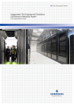
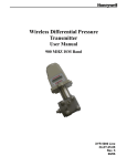
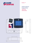
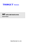
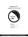
EIC- Engine Information Center
User Manual
11032748 Nov 2007 Rev. A
EIC-Engine Information Center
2
Contents
Before You Start
The Engine Information Center (EIC)
Brightness/Contrast Adjustment
Navigation Using Soft Keys
Main Menu
Setup Options
J1939 Monitor Controls
Installation/Mounting Instructions
Connection/Pinout settings
DP200 Series Accessories
Important Safety Information
4
5
6
6
8
25
29
33
37
38
40
11032748 Nov 2007 Rev. A
Sauer-Danfoss accepts no responsibility for possible errors in catalogs, brochures and other printed
material. Sauer-Danfoss reserves the right to alter its products without prior notice. This also applies to
products already ordered provided that such alterations are not in conflict with agreed specifications. All
trademarks in this material are properties of their respective owners. Red CAN™ is a trademark of the SauerDanfoss Group.
Sauer-Danfoss and the Sauer-Danfoss logotype are trademarks of the Sauer-Danfoss Group.
11032748 Nov 2007 Rev. A
EIC- Engine Information Center
© 2007 Sauer-Danfoss. All rights reserved. Printed in Europe.
3
EIC-Engine Information Center
4
Before You Start
Thank you for purchasing the Sauer-Danfoss DP200 Series Graphical Terminal.
This package contains the following items:
t One DP200 Series Graphical Terminal
t One Panel Seal Gasket
t One Mounting Bracket
t Four Bracket Mounting Screws
t One DP200 Series Graphical Terminals User Manual
Please ensure all parts are included prior to use.
11032748 Nov 2007 Rev. A
The DP200 Series Graphical Terminal comes installed with the
powerful and flexible Sauer-Danfoss Engine Information Center (EIC)
J1939 engine monitor software application. Use the application to
customize the look and feel of your individual engine monitoring needs
by creating and controlling analog and digital display information
in the screen configurations that work best for your performance
requirements. Navigate through diagnostic information and
configuration screens with ease by using the four context-dependent
soft keys located at the front of the display. Choose from 50 different
monitoring parameter profiles to customize the DP200 terminal.
Up to four signals can be monitored on each screen. Use the Engine
Information Center software to configure the DP200 for alarms and
alerts.
11032748 Nov 2007 Rev. A
EIC- Engine Information Center
The Engine Information Center (EIC)
5
EIC-Engine Information Center
6
Brightness/Contrast Adjustment
Adjust brightness and
contrast levels by pressing
the far left soft key. This will
display the brightness and
contrast soft key bar. The
bar will disappear after 3
seconds of inactivity.
Navigation
avigation Using Soft Keys
The
e DP200 Series Graphical Terminal is controlled
co
by navigation
through a set of four soft keys located at the lower front of the display.
The keys are context dependent. Soft key selection options are
displayed above each key and are dependent on the current navigation
location within the engine monitor software program. As a general
rule, the far right soft key is the selector button and the far left soft
key is the step back one screen key. To optimize full screen use, the
on-screen selections are not displayed when not in use. Press any soft
key to display current selection options. The selection options will be
displayed for three seconds.
11032748 Nov 2007 Rev. A
Brightness/
Contrast
Navigate
Up
Navigate
Down
Main
Menu
Exit/ Back
one screen
Navigate
Up
Navigate
Down
Select
Exit/ Back
one screen
Navigate
Up
Navigate
Down
Next
Screen Navigation
Brightness/Contrast
Press to access brightness and contrast settings.
Navigate Up
Navigate Down
Main Menu
Exit/Back one screen
Select
Next
Press up to move up through menu items.
Press up to move down through menu items.
Press to go to Main Menu screen.
Press to go back one screen.
Press to make selection.
Press to navigate to next digit or screen element.
11032748 Nov 2007 Rev. A
EIC- Engine Information Center
Navigation Using Soft Keys
7
EIC-Engine Information Center
8
Main Menu
Start Menu
Start Menu- Main Menu
The Main Menu screen is the
starting point for configuring
the DP200 Series Graphical
Terminal.
Main Menu
Basic Setup
Diagnostics
Use to set Time/Date, Language and Units
Use to set System Info, Access Fault Log and J1939 lists.
Screen Setup
Use to set Parameters, choose number of screens and
select screen. (PIN protected)
Use to reset trip and default settings, access CAN
information, select display settings and set PIN
information. (PIN protected)
System Setup
11032748 Nov 2007 Rev. A
Basic Setup
Overview
Use the Basic setup screen to set
time, language and display units
for the DP200 series terminal.
Basic Setup
Time/Date
Language
Units
11032748 Nov 2007 Rev. A
Use Time/Date to set, date and display style for time and
date information.
Use Language to set the system language. The default
language is English.
Use Units to set speed, distance, pressure, volume,
temperature and fuel rates and economy settings.
EIC- Engine Information Center
Main Menu
9
EIC-Engine Information Center
10
Main Menu
Basic Setup
Time/Date
Use Time/Date screen to set Time, Date,
calendar style and time style. Use up, down
select and next soft keys to navigate.
Language
Use Language screen to select program
language. Languages available, English,
French, German, Italian, Swedish and Spanish.
The default language setting is English.
11032748 Nov 2007 Rev. A
Basic Setup
Units
Use the up, down, select and next soft keys to
define unit measurements.
Unit Selection Options
Speed
Distance
Pressure
Volume
Temperature
Fuel Economy
Fuel Rate
11032748 Nov 2007 Rev. A
km/h, mph
km, mi
kPa, bar, lbs/ sq in
l, gal, imp gal
°C, °F
1/100 km, mpg, mpig
l/h, g/h, ig/h
EIC- Engine Information Center
Main Menu
11
EIC-Engine Information Center
12
Main Menu
Diagnostics
Overview
Use the Diagnostics screen
to display current system
information, view and monitor
fault logs and display all J1939
devices connected to the
graphical terminal.
Diagnostics
System Info
Fault Log
Device List
Quick Data
Selecting System Info will display hardware, software,
system and node information for connected devices.
Use fault log to view and monitor current and previous
fault information.
The Device List will list all currently connected J1939
devices.
Use Quick Data to set up a customized signal list that can
be quickly scrolled through in one signal per page format.
11032748 Nov 2007 Rev. A
Diagnostics
System Info
The system info screen displays the hardware
system serial number, current software
version, current system version and node
number. Only information is displayed in
the System Info window. No changes can be
made.
Fault Log
Fault information is saved and stored to the
fault log. Select either Active or Previous Faults
to monitor fault activity. Select specific faults
to list more information.
11032748 Nov 2007 Rev. A
EIC- Engine Information Center
Main Menu
13
EIC-Engine Information Center
14
Main Menu
Diagnostics
Fault Log: Active and Previous Faults
Selecting Active Faults in the Fault
Menu will display all active faults on the
CAN network.
Selecting Previous Faults in the Fault
Menu will display all previously active
faults on the CAN network.
11032748 Nov 2007 Rev. A
Diagnostics
Fault Pop-Up Alarms
When a fault is detected on the CAN
network, a flashing red warning alarm
will be activated and a fault information
pop-up window will be displayed listing
current fault information.
Warning lights will flash when a popup alarm occurs and will stay flashing
until acknowledged. Warning lights will
remain lit until the fault is no longer on
the CAN network.
Fault pop-up softkey actions
Select to clear pop up and return directly to previous display
information
Select to go to next fault information
Select to go to previous pop up information
Select to go to clear pop-up and go to the current active fault
complete information screen
11032748 Nov 2007 Rev. A
EIC- Engine Information Center
Main Menu
15
EIC-Engine Information Center
16
Main Menu
Diagnostics
Fault Pop-Up Alarms
t Faults that have been acknowledged and are no longer active
will be shown in the Currently Active Faults log in italics.
t Faults no longer active will also be displayed in the Previous
Faults log.
t Pop-up fault alarms can be disabled by setting the Fault PopUp to off in the CAN section of the System Setup menu.
11032748 Nov 2007 Rev. A
Diagnostics
Device List
The
he Device list page will list all J1939 devices
nd addresses that are currently being
and
mo
monitored on the network.
11032748 Nov 2007 Rev. A
EIC- Engine Information Center
Main Menu
17
EIC-Engine Information Center
18
Main Menu
Diagnostics
Quick Data
Th Quick Data function allows selected
The
sig
signals to be monitored in a scrollable single
vie
view display.
To select signals for display, press the far right
soft key.
Quick Data softkey
Scroll through signal list using the up and
down arrow soft keys and select/deselect
signals for Quick View monitoring by pressing
the far right (check mark) soft key. Signals
selected for display will show an asterisks to
the left of the signal name.
11032748 Nov 2007 Rev. A
Screen Setup
Overview
Use Screen Setup to enter
parameter settings, select number
of signal screens and select
individual screens for setup.
Screen Setup
Parameters
Set parameters for RPM, Speed, Fuel, Wheel and Pulse/
Revolutions information.
Number of
Screens
Select number of screens for information display. Select
from 1 to 4 screens for display.
Select Screen
Use to select screen to set up signal information. Number
of screens available are dependent on number of screens
selected.
11032748 Nov 2007 Rev. A
EIC- Engine Information Center
Main Menu
19
EIC-Engine Information Center
20
Main Menu
Screen Setup
Parameters
Define system parameter ranges for
revolutions per minute, speed, fuel, wheel
diameter and pulses per revolution display
settings.
Number of Screens
Select number of screens for display. Choose
from 1 to 4 screens. See page 25 for detailed
screen set up tutorial.
Select Screen
Select screen to customize. See page 25 for
detailed screen setup tutorial.
11032748 Nov 2007 Rev. A
System Setup
Overview
Use System Setup to monitor and
control application systems. Use
reset to default settings, make CAN
selections, control display settings,
set PIN configurations and reset
trip functions.
System Setup
Reset Defaults
CAN
Display
PIN Setup
Trip Reset
11032748 Nov 2007 Rev. A
Select to reset all system information to the default
settings status.
Select to customize CAN setting.
Select to customize display settings.
Use to set custom PIN settings.
Select to reset all trip information.
EIC- Engine Information Center
Main Menu
21
EIC-Engine Information Center
22
Main Menu
System Setup
Reset Defaults
Select Reset Defaults to reset all EIC settings to
original factory default settings.
CAN Settings
Use the CAN settings selection to make the
following selections:
11032748 Nov 2007 Rev. A
System Setup
CAN Settings
Engine Address Select engine address. Selection range is 0–253.
Conversion
Method
Select 1, 2 or 3 to determine how to interpret non-standard
fault messages. Consult engine manufacturer for correct
setting.
Fault Popup
Select on or off to enable or disable on screen popup
messages.
Display Settings
Display Setting
Startup
Screen
Buzzer
Output
Demo
Mode
11032748 Nov 2007 Rev. A
Select to enable/disable logo display
at startup
Select to enable/disable warning
buzzer functionality.
Select on/off to enable
demonstration mode.
EIC- Engine Information Center
Main Menu
23
EIC-Engine Information Center
24
Main Menu
PIN Protection
Change PIN Code
Refer to information on the following page for
PIN code information and PIN code change
information.
To reduce the potential for errors, Screen
Setup and System Setup menu options can
only be accessed by entering a PIN code. The
default code is 1-2-3-4. The PIN number can
be changed by using PIN Setup located in the
System Setup menu.
Trip Reset
Select Yes to reset all trip data.
11032748 Nov 2007 Rev. A
Selecting Screen Number and Types
1. Select from one to four
screens for signal monitoring.
Navigate to Main Menu>Screen
Setup>Number of Screens.
2. Select screen type for each of
the screens selected. Navigate
to Main Menu>Screen
Setup>Select Screen. Choose
from three types of screen setups.
Select screen type and press the
far right soft key (check mark) to
go to signal monitoring options.
11032748
2748 Nov 2007 Rev
Rev. A
EIC- Engine Information Center
Setup Options
25
EIC-Engine Information Center
26
Setup Options
Screen Variants
Screen Type 1
Type 1 is a two-up screen view
with two signal capacity.
Screen Type 2
Type 2 is a three-up screen view
with one large and two small
signal capacities.
Screen Type 3
Type 3 is a four-up display with
four small signal display capacity.
11032748 Nov 2007 Rev. A
Selecting J1939 Monitor Signals
3. After screen type selection,
select signals to monitor. Use the
up and down arrow soft keys to
cycle through available signal
selections.
4. After making a signal selection,
press the right arrow (Next) soft key
to go to the next selection area. Use
the up, down arrow, next and select
soft keys to select signal. Select the
right arrow soft key to move to the
next selection area.
11032748
32748 Nov 2007 Rev. A
EIC- Engine Information Center
Setup Options
27
EIC-Engine Information Center
28
Setup Options
Selecting J1939 Monitor Signals
5. Using the right arrow soft key will
rotate through the selections in a
clockwise rotation.
When finished with all screen
signal selections press the exit
(door symbol) soft key to return to
previous menus.
6. Navigate back for more screen
selections or press the Exit soft key 5
times to display current selections.
11032748 Nov 2007 Rev. A
The following tables list the J1939 engine and transmission parameters
that are available and can be monitored in the DP200 Graphical
Terminal.
For more information on setting up monitor controls in using the
Engine Information Center, please refer to Selecting J1939 Signals on
page 27.
11032748 Nov 2007 Rev. A
EIC- Engine Information Center
J1939 Monitor Controls
29
EIC-Engine Information Center
30
J1939 Monitor Controls
Symbols
Signal Monitor Functions
Symbol
Name/Function
Actual Engine Torque
Engine Air Inlet Temperature
Engine Coolant Level
Engine Coolant Pressure
Engine Coolant Temperature
Engine Exhaust Gas Temperature
Engine Hours
Engine Intake Manifold Temperature
Engine Oil Level
Units
%
°C, °F
%
psi, bar, Pa x 1000
°C, °F
°C, °F
Hours
°C, °F
%
Engine Oil Pressure
Engine Oil Temperature
Engine RPM
psi, bar, Pa x 1000
°C, °F
RPM
Engine Turbocharger Boost Pressure
Fuel Level
Wheel-based Vehicle Speed
Accelerator Pedal Position
psi, bar, Pa x 1000
%
km/h, mph
%
11032748 Nov 2007 Rev. A
Symbols
Symbol
Name/Function
Alternator Current
Alternator Voltage
Auxiliary Temperature
Average Fuel Economy
Trip Average Fuel Rate
Barometric Pressure
Current Gear
Distance Remaining
Engine Air Filter Differential Pressure
Units
Amp
Volts
°C, °F
1/100km, mpg,
impg
l/h, g/h, ig/h
psi, bar, Pa x 1000
F, N, R
km, m
psi, bar, Pa x 1000
Engine Air Inlet Temperature
Engine Injector Metering Rail 1 Pressure
Engine Injector Metering Rail 2 Pressure
Engine Intercooler Temperature
Engine Turbocharger Oil Temperature
Fan Speed
Engine Fuel Delivery Pressure
°C, °F
psi, bar, Pa x 1000
psi, bar, Pa x 1000
°C, °F
°C, °F
%
psi, bar, Pa x 1000
Fuel Rate
l/h, g/h, ig/h
11032748 Nov 2007 Rev. A
EIC- Engine Information Center
J1939 Monitor Controls
31
EIC-Engine Information Center
32
J1939 Monitor Controls
Symbols
Symbol
Name/Function
Fuel Remaining
Engine Fuel Temperature 1
Instantaneous Fuel Economy
Internal Voltage
Net Battery Current
Selected Gear
Torque Convertor Lock-up Engaged
Total Distance
Engine Total Fuel Used
Transmission Input Shaft Speed
Transmission Oil Pressure
Transmission Oil Temperature
Transmission Output Shaft Speed
Trip Distance
Trip Engine Hours
Units
l, gal, igal
°C, °F
1/100km, mpg,
impg
Volts
Amps
F, N, R
Engd, Dis
km, m
l, gal, igal
RPM
psi, bar, Pa x 1000
°C, °F
RPM
km, m
hrs
Trip Fuel
l, gal, igal
11032748 Nov 2007 Rev. A
Panel Bracket Assembly
Mounting and fastening Installation
t Fastening hole depth: 11 mm
t May be threaded M3 and used with
standard screws. Reassembly with selftapping screws may damage existing
threads in housing.
t Maximum torque: 0.9 Nm.
11032748 Nov 2007 Rev. A
wCaution:
Excessive screw
torque force may
cause damage to
housing.
EIC- Engine Information Center
Installation/Mounting Instructions
33
EIC-Engine Information Center
34
Installation/Mounting Instructions
Surface Mount
Panel Gasket Bracket
DP200-10107355
DP210-10105916
10105917
Panel Bracket
10107464
M3x10 Screw (x4)
11032748 Nov 2007 Rev. A
Panel Gasket Dimensions
100.5 mm [3.95 in] (±0.7 mm [0.27 in])
105.5 mm [4.15 in] (±0.7 mm[0.027 in])
t
t
t
11032748 Nov 2007 Rev. A
Gasket seal area crosshatched
Panel thickness: 2-5 mm
Interior edges chamfered 0.2- 0.5 mm
EIC- Engine Information Center
Installation/Mounting Instructions
35
EIC-Engine Information Center
36
DP200 Series Model Code Variants
A
B
Model Name
DP200
Graphical Display, IP 67 above panel
DP210
Graphical Display with USB
Inputs/Outputs
00
1 CAN port, 2 DIN/AIN
01
1 CAN port, 6 DIN/AIN
04
2 CAN ports, 2 DIN/AIN
Real Time Clock/ Low Temperature Functionality
C
D
E
F
00
No RTC and LTF
01
RTC and LTF
Flash Memory/Application Key
01
1MB
02
2MB without Application Key
03
2MB with Application Key
Application Log
00
None
04
4 MB
USB Port Type
00
None
01
USB Device
11032748 Nov 2007 Rev. A
DP200 Series- Deutsch Connector
7
12
6
1
DP200 Series pin assignments
1
2
3
4
5
6
7
8
9
10
11
12
Power groundPower supply+
CAN 0+
CAN 0–
AIN/ CAN Shield
See Code B option
See Code B option
See Code B option
See Code B option
DIN/AIN/FREQ
IN/CURRENT IN
DIN/AIN/FREQ
IN/CURRENT IN
DOUT (0.5A)
11032748 Nov 2007 Rev. A
Code B 00
Code B 01
Code B 04
N/C
N/C
N/C
N/C
DIN/AIN
DIN/AIN
DIN/AIN
DIN/AIN
N/C
N/C
CAN 1+
CAN 1-
EIC- Engine Information Center
Connection/Pinout settings
37
EIC-Engine Information Center
38
DP200 Series Accessories
Related Parts & Kits
DP200 Series Related Products Part Numbers
10106893
J1939 EIC CAN Engine Monitor Software
10100944
Deutsch Mating Connector Bag Assembly (20-24 AWG)
10102025
Deutsch Mating Connector Bag Assembly (16-20 AWG)
Electrical Connection Kits
10100944
12-pin Deutsch connection Kit
Contents:
10100738 DTM06-12SA 12-pin Deutsch connector
10100743 Deutsch terminal
10100741 WM 12S locking plug
Connection Tools
10100744
Deutsch stamped contacts terminal crimp tool, size 20
10100745
Deutsch solid contacts terminal crimp tool
11032748 Nov 2007 Rev. A
Related Parts & Kits (Continued)
DP200 Mounting Kit
10107354
DP200 Series Mounting Hardware Kit
Contents:
10107464 Mounting screws (x4), M3 x10
10105916 Panel gasket seal
10105917 Panel mounting bracket
DP210 Mounting Kit
10107264
DP210 Series Mounting Hardware Kit
Contents:
10107464 Mounting screws (x4), M3 x10
10107355 Panel gasket seal
10105917 Panel mounting bracket
Software
10101000
PLUS+1 GUIDE Software Application ( including Service Tool
and Screen Editor)
11032748 Nov 2007 Rev. A
EIC- Engine Information Center
DP200 Series Accessories
39
EIC-Engine Information Center
40
Important Safety Information
t %JTDPOOFDU ZPVS NBDIJOFT CBUUFSZ QPXFS CFGPSF DPOOFDUJOH QPXFS BOE TJHOBM DBCMFT UP UIF %1
t #FGPSF EPJOH BOZ FMFDUSJDBM XFMEJOH PO ZPVS NBDIJOF EJTDPOOFDU BMM QPXFS BOE TJHOBM DBCMF DBCMFT DPOOFDUFE
to the DP200
t %P OPU FYDFFE UIF %1 QPXFS TVQQMZ WPMUBHF SBUJOHT 6TJOH IJHIFS WPMUBHFT NBZ EBNBHF UIF %1 BOE
can create a fire or electrical shock hazard.
t %P OPU VTF PS TUPSF UIF %1 XIFSF øBNNBCMF HBTFT PS DIFNJDBMT BSF QSFTFOU
Using or storing the DP200 where flammable gases or chemicals are present may cause an explosion.
t 4PGUXBSF DPOöHVSFT UIF LFZQBE CVUUPOT PO UIF %1 %P OPU VTF UIFTF CVUUPOT UP JNQMFNFOU DSJUJDBM TBGFUZ
features. Use separate mechanical switches to implement critical safety features such as emergency stops.
t %FTJHO TZTUFNT UIBU VTF UIF %1 TP UIBU B DPNNVOJDBUJPO FSSPS PS GBJMVSF CFUXFFO UIF %1 BOE PUIFS
units cannot cause a malfunction that might injure people or damage material.
t 5IF QSPUFDUJWF HMBTT PWFS UIF %1 EJTQMBZ TDSFFO XJMM CSFBL JG IJU XJUI B IBSE PS IFBWZ PCKFDU *OTUBMM UIF
DP200 to reduce the possibility of it being hit by hard or heavy objects.
t *G ZPV CSFBL UIF QSPUFDUJWF HMBTT PG UIF %1 TDSFFO SFNPWF UIF %1 BOE JNNFEJBUFMZ SFUVSO JU UP 4BVFS
Danfoss for service.
t 4UPSJOH PS PQFSBUJOH B %1 JO BO FOWJSPONFOU UIBU FYDFFET UIF %1 TQFDJöFE UFNQFSBUVSF PS IVNJEJUZ
rating may damage the DP200.
t "MXBZT DMFBO UIF %1 XJUI B TPGU EBNQ DMPUI 6TF B NJME EJTIXBTIJOH EFUFSHFOU BT OFFEFE
t 5IF %1 JT OPU VTFS TFSWJDFBCMF 3FUVSO UIF %1 UP UIF GBDUPSZ JO DBTF PG GBJMVSF
11032748 Nov 2007 Rev. A
Sauer-Danfoss Mobile Power and Control Systems
– Market Leaders Worldwide
Sauer-Danfoss is a comprehensive supplier providing complete systems to the global mobile
market.
Sauer-Danfoss serves markets such as agriculture, construction, road building, material
handling, municipal, forestry, turf care, and many others.
We offer our customers optimum solutions for their needs and develop new products and
systems in close cooperation and partnership with them.
Sauer-Danfoss specializes in integrating a full range of system components to provide vehicle
designers with the most advanced total system design.
Sauer-Danfoss provides comprehensive worldwide service for its products through an
extensive network of Authorized Service Centers strategically located in all parts of the
world.
Sauer-Danfoss (US)
Sauer-Danfoss GmbH & Co. OHG
Sauer-Danfoss (Nordborg) ApS
Company
24539 Neumünster, Germany
Nordborgvej 81
2800 East 13th Street
Krokamp 35,
DK-6430 Nordborg, Denmark
Ames, IA 50010, USA
Phone: +49 4321 871-0
Phone: +45 7488 4444
Phone: +1 515 239-6000,
Fax: +49 4321 871-255
Fax: +45 7488 4400
Fax: +1 515 239 6618
www.sauer-danfoss.com
11032748 Nov 2007 Rev. A