1
Technical Manual
DRIVER DISTRACTION MANAGEMENT
USING SENSOR DATA CLOUD
© Green Networking Research Group
Department of Computer Science and Engineering
2nd Science Complex, Mokarram Bhaban, University of Dhaka
Dhaka- 1000, Bangladesh
Phone +880 2 9661920 • Ext 7448 • Fax +88 02 8615583
Information Society Innovation Fund (ISIF) Asia
March 2014
Table of Contents 1. INTRODUCTION .................................................................................................................. 5 1.1. DOCUMENT IDENTIFICATION .............................................................................................. 5 1.2. SYSTEM OVERVIEW ............................................................................................................. 5 1.2.1. SUBSYSTEMS USED: ............................................................................................................ 5 1.2.2. PLATFORMS AND UTILITIES ............................................................................................... 5 1.2.3. TOOLS AND SOFTWARES: ................................................................................................... 6 1.2.4. WEB AND CLOUD SERVICES: .............................................................................................. 6 1.3. DOCUMENT OVERVIEW ....................................................................................................... 6 1.4. REFERENCE DOCUMENTS ................................................................................................... 6 2. SYSTEM DESCRIPTION ..................................................................................................... 6 2.1. INTRODUCTION .................................................................................................................... 7 2.2. OPERATIONAL SCENARIOS.................................................................................................. 7 2.3. SYSTEM REQUIREMENTS ..................................................................................................... 7 2.3.1. POWER REQUIREMENTS: .................................................................................................... 8 2.3.2. OPERATING SYSTEM REQUIREMENTS: ............................................................................... 8 2.3.3. APPLICATION SOFTWARE REQUIREMENTS: ....................................................................... 8 2.3.4. CLOUD SERVICES REQUIREMENTS: .................................................................................... 8 3. RASPBERRY PI INITIALIZATION AND SETUP ........................................................... 9 3.1. RASPBERRY PI AS A MICROCONTROLLER.......................................................................... 9 3.2. UNBOXING RPI AND PREPARING SD CARD FOR SETUP: .................................................... 9 3.3. SETTING UP THE SD CARD: ................................................................................................. 9 3.4. SETTING UP RASPBERRY PI: ............................................................................................. 10 3.5. GETTING INTO R PI FROM PC: ......................................................................................... 10 3.6. INSTALL TOOLS AND LIBRARIES: ...................................................................................... 11 3.6.1. COMMAND LISTING: ......................................................................................................... 11 3.7. INSTALL, CONFIGURE AND INTEGRATE 3G MODEM: ....................................................... 12 3.7.1. MAKE SURE THE PI CAN SEE THE 3G DONGLE.................................................................. 12 3.7.2. DOWNLOAD AND SETUP PPP, UMTSKEEPER AND SAKIS3G ............................................ 13 3.8. INSTALL OPENCV:............................................................................................................. 15 3.8.1. UPDATE AND UPGRADE UBUNTU ..................................................................................... 15 3.8.2. INSTALL THE DEPENDENCIES ........................................................................................... 15 3.8.3. DOWNLOAD AND DECOMPRESS OPENCV ......................................................................... 15 3.8.4. COMPILE OPENCV............................................................................................................. 15 3.8.5. 5. CONFIGURE OPENCV .................................................................................................... 16 3.9. FINALIZE: ........................................................................................................................... 16 4. CAMERA INSTALLATION AND SETUP ....................................................................... 17 4.1. CREATE TEST DIRECTORY: ............................................................................................... 17 4.2. COPY THE EXECUTABLE AND THE XML FILES IN TEST:................................................... 17 4.3. CREATE SHELL FILE: ........................................................................................................ 17 4.4. RUN THE CAMERA MODULE: ............................................................................................. 17 5. CAMERA SENSING METHODOLOGY ......................................................................... 17 6. BLOOD PRESSURE AND HEART RATE MONITORING METHODOLOGY: ...... 18 6.1. CREATING A MOBILE HOTSPOT ....................................................................................... 18 6.2. ACCESSING BLIPCARE ....................................................................................................... 18 6.3. ACCESSING THE WEB PORTAL OF BLIPCARE .................................................................. 18 7. DATA TRANSMISSION METHODOLOGY .................................................................. 18 7.1. 7.2. 7.3. 7.4. 7.5. 7.6. 7.7. CONNECTING TO THE DATABASE ..................................................................................... 18 ALCOHOL DATA TRANSMISSION ...................................................................................... 18 TEMPERATURE DATA TRANSMISSION .............................................................................. 19 EYE MOVEMENT DATA TRANSMISSION ........................................................................... 19 SPEAK DETECTION DATA TRANSMISSION ....................................................................... 19 BLOOD PRESSURE AND HEART RATE DATA TRANSMISSION .......................................... 19 COMPILING AND RUNNING DATA TRANSMISSION METHOD: ......................................... 19 8. CLOUD COMPUTING ....................................................................................................... 21 8.1. 8.2. 8.3. 8.4. 8.5. CLOUD COMPUTING ENVIRONMENT ................................................................................ 21 IMPORTANCE OF CLOUD COMPUTING ............................................................................. 21 SETUP OF THE CLOUD SERVER ......................................................................................... 21 CONFIGURATION ................................................................................................................ 23 MANAGEMENT ................................................................................................................... 24 9. USER INTERFACE DESIGN ............................................................................................ 24 9.1. WORDPRESS-A WEBSITE MANAGEMENT SYSTEM ............................................................ 24 9.2. USABLE WEBSITES ............................................................................................................. 24 9.3. SEARCH ENGINE FRIENDLY SITES ..................................................................................... 24 9.4. ACCESSIBLE WEBSITES ..................................................................................................... 24 9.5. THE DISABILITY DISCRIMINATION ACT (DDA) .............................................................. 25 9.6. FUNCTIONALITY OF OUR WEBSITE .................................................................................. 25 9.6.1. GENERAL FEATURES ........................................................................................................ 25 9.6.2. WEBSITE MANAGEMENT................................................................................................... 25 9.6.3. FILE AND IMAGE MANAGEMENT ....................................................................................... 25 9.6.4. USER MANAGEMENT ........................................................................................................ 25 9.7. ADDING ECOMMERCE FUNCTIONALITY TO A DATABASE-DRIVEN WEBSITE .................. 26 9.8. TESTING THAT OUR WEBSITE WORKS IN DIFFERENT BROWSERS ................................... 26 9.9. CODING VALIDATION ......................................................................................................... 26 9.10. SECURITY.......................................................................................................................... 27 9.11. SECURITY TESTING .......................................................................................................... 27 10. SOFTWARE DESIGN ....................................................................................................... 27 10.1. SOFTWARE DESIGN PROCESS ......................................................................................... 27 10.1.1. SOFTWARE DEVELOPMENT ENVIRONMENT ................................................................... 27 10.1.2. SOFTWARE IMPLEMENTATION STAGES AND TEST PLANS ............................................. 27 10.2. SOFTWARE QUALITY ASSURANCE .................................................................................. 27 11. SYSTEM PERFORMANCE ............................................................................................. 28 11.1.1. PERFORMANCE TESTING ................................................................................................ 28 11.1.2. STATE OF THE SYSTEM AS DELIVERED .......................................................................... 28 11.1.3. FUTURE IMPROVEMENTS ................................................................................................ 28 12. SAFETY IMPLICATIONS ............................................................................................... 28 13. CONCLUSIONS ................................................................................................................ 29 1. Introduction
1.1. Document Identification
This document describes the design of the Driver Distraction Management Using Sensor Data
Cloud. This document is prepared by Green Networking Research Group, Department of
Computer Science and Engineering, University of Dhaka, Bangladesh
1.2. System Overview
Driver distraction can be defined as any type of event that takes away drivers visual, manual and
cognitive attention from the driving task. To reduce the number of road accidents due to driver
distraction, we design and implement a system for monitoring and controlling driver distraction in
this project, which is cost-effective and highly accurate. This system is implemented using sensor
based data collection and transmission scheme. To manage the collected data, a cloud data
management infrastructure and a user-friendly interface is used. We analyse, design and
implement innovative system services such as real-time information collection and reporting on
driver’s healthcare, providing alert messages in emergency cases, distraction levels
determination, etc. At the end of the implementation period, purchase of all the sensors, data
collection from the sensors, training on cloud infrastructure and services, writing research paper
for dissemination of knowledge, creation of database, conduction of workshops and extensive
verification procedures have been performed.
The Driver Distraction Management Using Sensor Data Cloud module has been assembled from
the following subsystems, whose details are outlined in this report.
1.2.1.
Subsystems used:
•
Raspberry PI module
•
Huawei E303 HSPA Modem Weigh/Count
•
HD Webcam Factory User Options
•
3G SIM card
•
GPS position and vehicular security condition identifier devices
•
2Amp 5V micro USB Power Supply
•
Blip-Care Blood Pressure and Heart Rate measurement Device
•
Alcohol vapour measurement sensors.
•
Body temperature measurement sensors.
•
ECG/EEG measurement sensors.
•
Microcontroller circuitry for sensor management
1.2.2.
Platforms and Utilities
•
Java ( Open JDK 7)
•
Open CV
•
Hostapd
•
Sakis3G
•
UMTS Keeper
•
GNOME Scheduler
•
MySQL JDBC Connector.
•
Python
•
Flow Code
•
PHP
•
MySQL
•
PHPmyAdmin
1.2.3.
Tools and Softwares:
•
Win32 Disk Imager
•
Putty
•
WinSCP
•
FileZilla
•
Connectify
1.2.4.
Web and Cloud services:
•
Google Cloud Services.
•
Dedicated VPS services.
1.3. Document Overview
This document details the design and implementation process of the Driver Distraction
Management Using Sensor Data Cloud. It first describes the system as a whole before
going into detail for each individual module. Interface designs as well as test carried out
are also detailed.
1.4. Reference Documents
The present document is prepared on the basis of the following reference documents, and
should be read in conjunction with them.
§
§
§
§
“The role of driver distraction in traffic crashes.” Prepared by Jane C. Stutts,
Donald W. Reinfurt, and Loren Staplin, University of North Carolina, Highway
Safety Research Center, Chapel Hill, NC, 2001.
Study on Driver Distractions” by California Department of Motor.
Vehicle,http://www.dmv.ca.gov/pubs/brochures/fast_facts/ffdl28.htm, Accessed
on 21June, 2012.
Government of People’s Republic of Bangladesh, Ministry of Communication,
Bangladesh Road Transport Authority, National Road Safety Strategic Action
Plan 2011-2013.
“Driver Distraction, Telematics Design, and Workload Managers: Safety Issues
and Solutions”, by Paul Green, SAE International 2004, paper number 2004-210022.
2. System Description
This section intends to give a general overview of the basis for the system design, of its division
into hardware and software modules, and of its development and implementation.
2.1. Introduction
The Driver Distraction Management Using Sensor Data Cloud can generally be divided
into two components, hardware and software.
Hardware components include:
§
Raspberry PI module
§
Huawei E303 HSPA Modem Weigh/Count
§
HD Webcam Factory User Options
§
3G SIM card
§
GPS position and vehicular security condition identifier devices
§
2Amp 5V micro USB Power Supply
§
Blip-Care Blood Pressure and Heart Rate measurement Device
§
Alcohol vapour measurement sensors.
§
Body temperature measurement sensors.
§
ECG/EEG measurement sensors.
§
Microcontroller circuitry for sensor management
The software components:
§
Win32 Disk Imager
§
Putty
§
WinSCP
§
FileZilla
§
Connectify
§
Google Cloud Services.
§
Dedicated VPS services.
Main controller and communication management unit: Raspberry PI
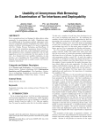
2.2. Operational Scenarios
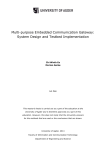
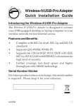
The block diagram below is a representation of how each sub-module is linked to each
other. The system can operate in one mode, user mode.
This system will contribute in managing the driver’s physical and mental condition, and
also the performance of the driver. Under the driver distraction monitoring and controlling
system, whenever the physical or mental condition of the driver deteriorates beyond a
threshold or the driver is somehow distracted, an alert message will be sent to the driver.
This mechanism will decrease the probability of road accident due to driver distraction and
thus it will be directly useful to vehicle drivers and vehicle owners and they will be the
primary user of this driver distraction monitoring and controlling system.
2.3. System Requirements
The operational scenarios considered place certain requirements on the system, and on
the modules that comprise it.
2.3.1.
Power Requirements:
USB port
USB port
The Raspberry PI system is powered by a 2Amp 5V micro USB Power Supply
when running. The alcohol and temperature circuitry is powered by 20V car
battery.
Power
Power slot
adapter
adapter slot
SDSD
card
card
SD card slot
Raspberry PI
3G
3Gmodem
modem
26 pin
pin male
male connector
connector
26
Connection for alcohol and
temperature circuitry
Figure 1: Block Diagram of the System
2.3.2.
Operating System Requirements:
We need Windows XP or Linux or MAC OS to run our Raspberry PI
2.3.3.
Application Software Requirements:
We some application software such as Virtual Router and putty.
2.3.4.
Cloud Services Requirements:
We use Google Cloud services and dedicated VPS services.
3. Raspberry PI Initialization and Setup
Raspberry PI is the main system module that is housing the other sub-modules. Below we
describe the initialization and setup procedure for Raspberry PI.
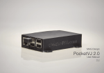
3.1. Raspberry PI as a microcontroller
We use Figure
Raspberry
PI as our main
2: Raspberry
PI communicating module. Raspberry PI is a mini Personal
Computer (PC). We can have the full flexibility of coding, debugging, modelling, finalizing
and most importantly maintaining the system. It is small and easily integratable with all the
circuitry and devices.
Moreover, we are using Debian version for ARM processors. Debian is famous to be the
most stable linux distro. So, we have a PC with Debian, that supports almost every
programming language and platforms. These are the prime reasons behind choosing
Raspberry PI among all other options.
3.2. Unboxing RPI and preparing SD card for setup:
We need a SD card to run the Raspberry PI. It is the Hard Disk for this device. We
recommend the capacity of the card to be at least 8GB. Then we need to download the
.img file from raspberry images directory. We prefer the Debian platform. So, we need to
download Raspbian image from the website http://www.raspberrypi.org . 3.3. Setting up the SD card:
Now, we have the SD card and the Raspbian image. We need to insert the SD card into
the card reader. Download the application named Win32 Disk Imager from
http://www.sourceforge.com and open it. Then, select the downloaded image to write on
the SD card. Select the desired SD card to be written on. Then click the “Write” button.
After finishing the operation eject the card.
3.4. Setting up Raspberry PI:
Now, SD card is ready for booting up. Connect the 2A 5V power supply to the R PI power
slot. It will automatically finish setting itself up. Give it about 2minutes of time. Then you
are ready to use Raspberry PI.
3.5. Getting
into R PI from PC:
Figure 3: Setting up Raspberry PI
We want to control, use and program R PI from our PC. So, we need to create a home
network to connect to the R PI. Now, we will download (http://www.connectify.me ) and
install Connectify software. We now share the working internet connection through an
Ethernet interface (alternatively, we can use WiFi, but connecting using Ethernet makes it
more consistent and easy). Now, from the shared Ethernet interface we will connect to the
R PI’s Ethernet interface using a CAT-5 wire with RJ45 connectors.
After connecting the Ethernet interfaces and starting Connectify, Power ON the R PI. After
a while, in Connectify’s connected devices list a device named “raspberrypi” will appear.
Write down the IP address of the device.
Now, download and install the software named “putty”. Open it and in SSH tab, give the
written ip there and click the open button. Now a terminal will appear. It is the bash
terminal from the newly installed Raspberry PI.
We login to the R PI using username “pi” and password “raspberry”. The first thing is to do
with the terminal is extending the current root partition which can be done running the
command “sudo raspi-config”. An interactive shell will appear and it is easy to configure
as needed.
We have used connectify to create virtual router. Anyone who has a physical router can
easily connect the Raspberry PI with it via CAT5/6 Ethernet cable and configure it
accordingly.
Figure 4: Getting into R PI from PC terminal snapshot
3.6. Install tools and libraries:
3.6.1.
Command Listing:
3.6.1.1. Commands to Upgrade:
Use these commands to update and upgrade the current
installation in Raspberry PI.
i.
sudo apt-get update
ii.
sudo apt-get upgrade
3.6.1.2. Commands for Java Installation:
JDK + JRE (OpenJDK 7)
i.
sudo apt-get install openjdk-7-jdk
ii.
sudo apt-get install openjdk-7-jre
3.6.1.3. Python Serial Library Commands
i.
sudo apt-get install python-serial
3.6.1.4. GNOME schedule Commands
i.
sudo apt-get install gnome-schedule
3.6.1.5. MySQL support for JDBC:
Download MySQL JDBC connector JAR file from oracle website
to the home directory /home/pi.
3.7. Install, configure and integrate 3G modem:
Here we used Huawei E303 HSPA modem. We are giving the tutorial for this model.
3.7.1.
Make sure the Pi can see the 3g Dongle
To get more information about the USB devices connected to the Pi, we use the
command 'lsusb'. Open a terminal window and type:
lsusb
Should give an output similar to this:
Bus 001 Device 002: ID 0424:9512 Standard Microsystems Corp.
Bus 001 Device 001: ID 1d6b:0002 Linux Foundation 2.0 root hub
Bus 001 Device 003: ID 0424:ec00 Standard Microsystems Corp.
Bus 001 Device 010: ID 12d1:1446 Huawei Technologies Co., Ltd.
E398 LTE/UMTS/GSM Modem/Networkcard
lsusb lists the usb devices connected to the Pi, either directly or through the hub.
I've highlighted the parts of the output that indicates the 3g dongle can be seen
by the Pi. Yours should look similar to this, although it will vary from model to
model - most 3g dongles on the market seem to be a Huawei of one flavour of
another at the moment. So long as there is a mention of 'modem' or 'UMTS', you
should be laughing. What you don't want to see at this stage is this:
Bus 001 Device 010: ID 12d1:1436 Huawei Technologies Co., Ltd.
We will install usb_modeswitch. To install, in the terminal window type:
sudo apt-get install usb-modeswitch
Now in terminal type:
sudo reboot
and wait for getting rebooted and reconnect the Raspberry PI with putty again.
Now, type:
lsusb
And you should see,
Bus 001 Device 010: ID 12d1:1436 Huawei Technologies Co., Ltd.
tell the operating system the vendor ID and device ID. More information on USB
identification can be found on the debian wiki. Notice that the first 4 characters of
the device ID (vendor ID) are the same in both examples, but the last 4 (device
ID) have changed. Usb-modeswitch forces the operating system to use the
combination that corresponds to the 3g modem.
Now type,
sudo nano /etc/usb_modeswitch.conf
and append the lines to the file written below:
DefaultVendor = 0x12d1
DefaultProduct = 0x1506
MessageEndPoint = "0x01"
MessageContent =
"55534243000000000000000000000011060000000000000000 000000000000"
Hit Ctrl+O, Enter, Ctrl+X to save changes and exit.
3.7.2.
Download and setup ppp, UMTSKeeper and Sakis3g
3.7.2.1. pppd
The ppp package will install the point to point protocol daemon,
which will manage the connection between you and your 3g
provider. The package can be installed via the terminal with the
command:
sudo apt-get install ppp
Nothing further needs to happen with pppd, it should just sit
there in the background, as a daemon are supposed to, waiting
for Sakis3g to control it.
3.7.2.2. UMTSKeeper
UMTSkeeper is used to automatically reconnect the 3g dongle
using the Sakis3g script should the connection drop, which
actually happens with monotonous regularity in Kenya.
Download and unpack UMTSkeeper by issuing the following
commands from the terminal window:
sudo mkdir umtskeeper
cd umtskeeper
sudo wget "http://zool33.unigraz.at/petz/umtskeeper/src/umtskeeper.tar.gz"
sudo tar -xzvf umtskeeper.tar.gz
sudo chmod +x umtskeeper
The first command created a folder called 'umtskeeper' in the
current directory you are in. To confirm what this directory is,
type 'pwd'. Make note of the output, as we will need the full path
to automate UMTS keeper later. Now we will download Sakis3g
into the same directory to keep things simple.
3.7.2.3. Sakis3g
Sakis3g is a script used to make a 3g connection. You need to
be able to provide a few details: your APN, the PIN for your SIM
card and your username and password if your provider requires
them. This information can (hopefully) be found on your
providers website or in the documentation that came with your
simcard/dongle. If not, a search on google for 'your
provider APN settings' should unearth them.
The sakis-3g.org website has been down for some time.
Fortunately somebody has uploaded a copy of the script to
SourceForge. To download and unpack it, issue the following
commands from the terminal window:
sudo wget "http://downloads.sourceforge.net/project/vimn4n0/sakis3g.tar.gz?r=http%3A%2F%2Fsourceforge.net%2Fpro
jects%2Fvimn4n0%2Ffiles%2F&ts=1363537696&use_mirror=tene~t" -O
sakis3g.tar.gz
sudo tar -xzvf sakis3g.tar.gz
sudo chmod +x sakis3g
Now test UMTSkeeper. The command at first may look a bit
confusing (the details are for our connection):
./umtskeeper --sakisoperators "USBINTERFACE='0'
OTHER='USBMODEM' USBMODEM='12d1:1436'
APN='CUSTOM_APN' CUSTOM_APN='wap' SIM_PIN='1234'
APN_USER=' ' APN_PASS=' '" --sakisswitches "--sudo -console" --devicename 'Huawei' --log --silent --monthstart 8 --nat
'no'
Breaking it down a little, these are the areas that you will need
to change:
USBMODEM: The Device ID we found using the lsusb
command earlier
CUSTOM_APN, APN_USER, APN_PASS, SIM_PIN:
Information about your sim card and your providers data
network.
A full breakdown of the parameters can be found on
the UMTSKeeper site.
Now put a command on the terminal:
crontab –e
After the last line of the file add the following single line, edited
to show your path to the umtsfolder you found with the 'pwd'
command earlier:
@reboot PATH GOES HERE/umtskeeper --sakisoperators
"USBINTERFACE='0' OTHER='USBMODEM'
USBMODEM='12d1:1436' APN='CUSTOM_APN'
CUSTOM_APN='wap' SIM_PIN='1234' APN_USER=' '
APN_PASS=' '" --sakisswitches "--sudo --console" --devicename
'Huawei' --log --silent --monthstart 8 --nat 'no'
Hit Ctrl+O, Enter, Ctrl+X to save changes and exit.
Now reboot using: sudo reboot
We are done with 3G modem now.
3.8. Install OpenCV:
Install OpenCV on Ubuntu Linux is a bit long but very easy. Simply, follow these steps:
3.8.1.
Update and Upgrade Ubuntu
Open your terminal and execute:
sudo apt-get update
sudo apt-get upgrade
3.8.2.
Install the Dependencies
Now execute:
sudo apt-get install build-essential libgtk2.0-dev libjpeg-dev libtiff4-dev libjasperdev libopenexr-dev cmake python-dev python-numpy python-tk libtbb-dev
libeigen2-dev yasm libfaac-dev libopencore-amrnb-dev libopencore-amrwb-dev
libtheora-dev libvorbis-dev libxvidcore-dev libx264-dev libqt4-dev libqt4-opengldev sphinx-common texlive-latex-extra libv4l-dev libdc1394-22-dev libavcodecdev libavformat-dev libswscale-dev
3.8.3.
Download and Decompress Opencv
Execute:
wget “http://downloads.sourceforge.net/project/opencvlibrary/opencvunix/2.4.8/opencv-2.4.8.zip?r=&ts=1392703029&use_mirror=skylink”
unzip opencv-2.4.8.zip
3.8.4.
Compile Opencv
Now, in your terminal, make sure you are within the OpenCV directory and
run the following commands:
mkdir build
cd build
cmake -D WITH_TBB=ON -D BUILD_NEW_PYTHON_SUPPORT=ON -D
WITH_V4L=ON -D INSTALL_C_EXAMPLES=ON -D
INSTALL_PYTHON_EXAMPLES=ON -D BUILD_EXAMPLES=ON -D
WITH_QT=ON -D WITH_OPENGL=ON ..
make
sudo make install
3.8.5.
5. Configure Opencv
In your terminal, execute:
sudo nano /etc/ld.so.conf.d/opencv.conf
Add the following line and save it:
/usr/local/lib
Now, in your terminal, execute:
sudo ldconfig
Again, execute:
sudo gedit /etc/bash.bashrc
Add the following two lines at the end of the file and save it:
PKG_CONFIG_PATH=$PKG_CONFIG_PATH:/usr/local/lib/pkgconfig
export PKG_CONFIG_PATH
Finally, reboot your computer.
3.9. Finalize:
Execute,
sudo pico /etc/inittab
The last line should be changed to,
#T0:23:respawn:/sbin/getty -L ttyAMA0 115200
Execute,
sudo nano /boot/cmdline.txt
delete the whole line and paste this
dwc_otg.lpm_enable=0 console=tty1 root=/dev/mmcblk0p2 rootfstype=ext4
elevator=deadline rootwait
Hit Ctrl+O, Enter, Ctrl+X
Now the total system is ready for the operation. Please, compile and run source codes or
patch the given firmware accordingly. 4. Camera installation and setup
For monitoring drowsiness, eye movement, speaking behaviour, texting and phone
calling we use a HD camera the setup procedure is given below:
4.1. Create test directory:
In the Desktop of Raspberry module, create a directory named test using the following
command in your terminal:
cd /home/pi/Desktop
mkdir test
4.2. Copy the executable and the xml files in test:
Copy all the xml files created after compiling the camera operation module to the test
directory. Also copy the executable contest file to test directory.
4.3. Create Shell File:
Open your terminal and execute the following commands:
cd /home/pi/Desktop
touch camera_schedule.sh
Open camera_schedule.sh using any file editor and write following lines in the file:
Cd /home/pi/Desktop/test
./contest
Save and close the file.
4.4. Run the camera module:
The camera module will execute for 30 seconds and terminate. To run the camera
module repeatedly after 2 minutes, open your terminal and execute
crontab –e
Go to the end of the file and write:
*/2 * * * * sudo /home/pi/Desktop/camera_schedule.sh
Press Ctrl+O to write and press Enter to confirm the writing. Now, press Ctrl+X.
5. Camera Sensing Methodology
Drowsiness and speaking detection system have been implemented over C/C++ and
OpenCV platform. A freeware library flandmark has been used for eye corner and mouth
corner recognition purpose. Image size has been restricted to 320X240 as the computing
system raspberry PI gets poor responses with images of bigger sizes. In order to detect
drowsy eyes a combined approach of OpenCV realtime object recognition function and
adaptive threshold along with vertical scanning has been used here. Both OpenCV and
flandmark library help to point out appropriate face features in image. Later, adaptive
threshold helps to reduce the illumination problem from the captured noisy images and to
figure out the remedy of driver’s drowsiness detection. For speaking detection, we use
OpenCV haar object detection function along with adaptive threshold for binaraization. The
binarized image is later used to approximate the mouth height and from the outcome of
current mouth height to width ratio, we guess the driver’s speaking state. Speaking and
drowsiness warning along with device ID number is written to activityLog.txt after a minute
interval. If driver is not in the seat or face can not be recognized due to distraction, an
alarming message is also written to the activityLog.txt. Shortcomings regarding to this
system is that driver must not use spectacles through driving as reflection might give
erroneous indication about the state. Though Haar object detection for spectacles has been
used for optimized eye detection, illumination and reflection often could not give reliable
information with spectacles. It gives best results when driver’s face aligned straight to the
camera.
6. Blood Pressure and Heart Rate Monitoring Methodology:
We have used Blipcare blood pressure and heart rate monitoring device. Blipcare is Wi-Fi
enabled so we setup our device by accessing its ip address.
6.1. Creating a Mobile Hotspot
We can create a mobile Hotspot on the driver’s smartphone. Using wireless tethering
service provided by the smartphone we create a mobile hotspot. Of course, this will need
the mobile data functionality to be active.
6.2. Accessing Blipcare
On power up blipcare shows an AP sign. This is transmitting connection beacon. Scanning
the vicinity will show the device on the wireless connection list. Connecting to the device
and accessing it via the private IP 192.168.101.1 will give the user access to hook the
device to an internet connection. By providing credentials, one must give the mobile
hotspots credentials.
6.3. Accessing the Web Portal of Blipcare
Programmers have written a java code to automatically login to users account, fetch the
latest data, and store it in the database. This program is running constantly and whenever
there is a new data available it updates the database.
7. Data Transmission Methodology
Camera Data is written in a file in Desktop named ‘ActivityLog.txt’. Alcohol and Temperature
data is collected in a file at /home/pi named ‘templog.txt’. Data form theses files is read,
transmitted, stored in a mirror file and erased from these files using a java program. That
java program is also used to connect to a remote database and data is sent continuously to
that remote database. Process of connecting to the remote server and transmitting data is
described below:
7.1. Connecting to the Database
MySQL JDBC driver is used to connect to the remote server. Connection at port 3306
(MySQL port) to the remote server is established. To send data to a specific table in the
database server, standard MySQL query is made and executed.
7.2. Alcohol Data Transmission
Alcohol data is sensed for a minute form the file. Data from the file is parsed using the
java split() method. If the data is above a threshold level, data is accumulated. When the
time stamp of one minute is over, all the accumulated data is averaged and sent to the
database. Threshold level is set judiciously after going through a number of trial and error
steps. At the time of transmission, a mirror file named ‘tampMirror.txt’ is created where a
copy of the sensed data is kept.
7.3. Temperature Data Transmission
00Temperature data is kept in the same file ‘templog.txt’ along with the alcohol data.
Temperature is processed in the same way as alcohol data. Temperature data is
originally measured in ‘Celsius’ scale and then converted to ‘Fahrenheit’ scale. The
temperature values are also observed for a minute, averaged, mirrored and finally
transmitted. The mirroring file is also the ‘tempMirror.txt’.
7.4. Eye Movement Data Transmission
Data from camera is kept in the Desktop in a file named ‘Activitylog.txt’. If the eyes of the
user are open the data is ‘0’ and if eyes are closed, data is ‘1’. If the eyes are not
detected, data is ‘-1’. Data value containing ‘-1’ is ignored. All other values are summed
and averaged and then sent to the database. In this case, the mirror of the sensed data is
kept in a file named ‘activMirror.txt’ in Desktop.
7.5. Speak Detection Data Transmission
Speak detection is performed by the camera. In this case also, data value is ‘0’ for not
speaking, ‘1’ for speaking and ‘-1’ if the face of the user is not detected. Data for speaking
is also summed and averaged for a minute and sent to the server.
7.6. Blood Pressure and Heart Rate Data Transmission
Blood pressure and heart rate monitoring has been done by Blipcare blood pressure
monitoring device. It is a Wi-Fi enabled device the blood pressure and heart rate
monitored through this device will be sent to Blipcares server, which could be accessed
through their web portal. A Java program has been developed to fetch those data to our
own server. We need a mobile hotspot paired with Blipcare to access the internet.
7.7. Compiling and Running Data Transmission Method:
In your Desktop, create a directory named DBConnect. Go to your terminal and type:
cd /home/pi/Desktop
mkdir DBConnect
Copy the file DataSend.java file and the MySQL connector package in the DBConnect
directory. Use the
cp ‘filename’ ‘destination-address’
command to copy files.
Compile the DataSend.java file. Open your terminal and write:
cd /home/pi/Desktop/DBConnect
javac DataSend.java
In your Desktop create a shell file to run the data transmission file. Open your terminal
and wirte:
cd /home/pi/Desktop
touch DataSend.sh
nano DataSend.sh
A file named DataSend.sh will open. Write the following lines in the file:
cd /home/pi/Desktop/DBConnect
java DataSend
Now, open crontab.
crontab –e
Write the following line at the end of crontab to run the data sending file repeatedly after
one minute.
*/1 * * * * sudo /home/pi/Desktop/DataSend.sh
Press Ctrl+O to write and press Enter to confirm writing. Finally, press Ctrl+X to exit
crontab.
The following code fragment is used for accessing the database from a java program:
//database..... Connection conn = null; Statement stmt = null; ResultSet rs = null; try { // Loading Driver Class.forName(driverName); // Creating Connection System.out.println("it works..."); conn = DriverManager.getConnection(connectionUrl, userName, password); // Setting auto commit false conn.setAutoCommit(false); System.out.println("Databese Connection Done........"); } catch (ClassNotFoundException e) { System.out.println(e.toString()); System.out.println("Error In Connection"); System.exit(0); } catch (SQLException e) { e.printStackTrace(); } try { //date and time SimpleDateFormat sdfDate = new SimpleDateFormat("yyyy-‐MM-‐dd HH:mm:ss"); Date now = new Date(); String strDate = sdfDate.format(now); System.out.println(strDate); // Creating Statement stmt = conn.createStatement(); // Creating Query String String updateQuery1 = "INSERT INTO "+"snsr_bph "+"VALUES "+"( '"+strDate+"' , "+systi+", "+diai+", "+ hri+", '"+regno +"')"; stmt.executeUpdate(updateQuery1); // Calling commit() method conn.commit(); } catch (Exception e) { e.printStackTrace(); } finally { // Closing Connection if (conn != null) { try { conn.close(); } catch (SQLException e) { } } if (stmt != null) { try { stmt.close(); } catch (SQLException e) { } } if (rs != null) { try { rs.close(); } catch (SQLException e) { } } System.out.println("Connection Closed.........."); } }
8. Cloud Computing
8.1. Cloud Computing Environment
In cloud computing, resources (compute, Disk space, Request per minute etc.) can be
scaled dynamically according to user requirement. To providing greater user access to
the stored data, improve quality of the services provided to the users and dynamically
scale database size, we have used Google Cloud Computing Environment. We have
used Google ‘Compute Engine’ for hiring an instance where our database and web-server
has been installed.
8.2. Importance of Cloud Computing
Cloud computing environment for web-server is necessary. This is because, as the time
goes, the size of the database will increase exponentially. So, a highly scalable and
robust server is a must. Cloud providers supply VM instances which assures these
qualities with a relatively low price. We don’t need big capital to buy servers; rather we
hire them from cloud. In cloud computing, we can also dynamically set the rate of user
access per minute which will help to improve quality of services provided to user when the
number of user increases.
8.3. Setup of the Cloud Server
First, create an account in Google Cloud.
Press the Go to my console link. Then create a new project.
After creating the project, press the compute engine link. Then enable billing for the
compute engine by giving the necessary information and bill pay card information. Then
create a new instance by pressing the button ‘new instance’.
Give the information regarding the instance like name, description, instance type, zone,
additional disk and image if required. Select a static IP address and finish the task by
providing the access information. After creation of the instance, information about that
instance will be shown.
8.4.
Configuration
By default in the cloud instance, Google gives you latest Debian distro installed. You need
to create a SSH private key according to the User Manual of Google Cloud services. Using
the private key, login to the cloud server using putty.
Figure 5 Logging into Google Cloud
The next step is to install Apache server, MySQL database server and PHP libraries for
getting started with Web services. The easiest way is to create a LAMPP stack (details can
be found in https://www.digitalocean.com/community/articles/how-to-install-linux-apachemysql-php-lamp-stack-on-debian).
After installing LAMPP stack we are ready to roll. Now, we need to configure apache
server to host the websites. Apache has its own documentations on detailed server
configuration. To control and maintain MySQL server easily, we use PHPMyAdmin.
8.5.
Management
We back up our running services and their data and synchronize accordingly the main
server with the back-up server. So, we create the exact copy of the database and website
files in another VPS (Virtual Private Server) and this needs to be done periodically. We
create dynamic websites to provide services for the product users. We ensure data
integrity and user affability. All the data are automatically backed up by our maintenance
system and the cloud itself. Debian is vastly used in servers of corporate use. So, reliability
is guaranteed.
9.
User Interface Design
9.1. Wordpress-a website management system
We have developed our website in wordpress CMS platform. The Wordpress CMS allows
the user to easily update the text, images and other content on the website without the
need for technical staff or prior knowledge of website maintenance. Wordpress CMS is a
web-based system, so it can be used to amend our site where ever we are in the world as
long as we have access to the internet. This ensures our website is always up-to-date and
allows us to react quickly and make changes instantly. Wordpress CMS is extremely
powerful but it has been designed specifically to allow inexperienced users to take control
of their site with ease and confidence.
9.2. Usable websites
We design all our websites with usability in mind, which means the sites are easy to use
and the users can easily find the information they need. We ensure the following things in
our website.
§ The navigation is clear and easy to use
§ The user find what they want in the minimum amount of clicks
§ The pages are quick to download.
9.3. Search engine friendly sites
We ensure that all aspects of our website are search engine ready, using site optimization
techniques, so that search engines can easily access our entire website effectively. For
this reason our website ensures that:
§
URLs of the site include keywords relating to the content of the page
§
Every page has a title describing what the page is about this will be displayed by
Google and at the top of the browser
§
Every page has a meta-description which is used by Google as the description
of the site
§
Every page has a heading displayed at the start of the page content
§
There is no content which the search engines cannot read due to flash or frames
9.4. Accessible Websites
An accessible website is one which all people can access on any browser, operating
system, screen size or device. With the increasing use of SmartPhone, (especially iPhones
and Androids) and the use of games consoles and large format televisions to view the
internet; it is essential that any website works across all devices and many different types
of browsers. By using CSS and template technology our websites are highly accessible.
We also ensure that our website is able to be printed out in a clear format.
9.5. The Disability Discrimination Act (DDA)
The Disability Discrimination Act (DDA) stipulates that websites must meet a minimum
standard of accessibility. Our accessible websites help people with limited dexterity, low
vision, or have to view the website with the help of a screen reader.
9.6. Functionality of our Website
Just as any popular website, our website and user support has all the essential features
and some more. Functionalities are described below:
9.6.1.
General Features
§
§
§
§
§
§
9.6.2.
Website management
§
§
§
§
§
9.6.3.
Easy management of the navigation and site menus on the website
XSL Template Architecture
Check status of our site and if pages have any validation errors
Intelligent content caching
Site statistics and integration with Google Analytics
File and image management
§
§
§
9.6.4.
Simple and easy to use - if anyone can use Microsoft WORD he/she
can use Wordpress.
Secure on-line administration area – we can update our website
anywhere in the world
Instantly change website content by us - no technical staff required!
Complete separation of design and content
Compatibility with all major platforms - desktop, laptop, netbooks,
games consoles or mobile phones (iPhone, Smart Phones, iPad)
Import and export to other systems – e.g. you can export your
customer database details into our (or your own) email broadcasting
system
Document Vault - Upload all types of files to the site
Scale and crop images to reduce or increase the size
Upload and storage of multi-media files, including videos and sound files
User management
9.6.4.1. Front-end
This is how the data is displayed to the user. This consists of
forms, search results and data extracted from the data-tables
e.g. details of a specific product.
9.6.4.2. Admin area
This is the control panel that we access (with a password) to
manage our website. The database elements of our website are
managed through the “Form/database manager” and the “Data
manager”.
9.6.4.3. Back-end
This is the area where the data is stored in a series of linked
tables and is only accessed by our programmers
9.6.4.4. User-areas
This is a secure area that can be accessed by a customer or
member. They can either be a read-only area where they can
access secure content or an interactive area where they can
amend their profile and see specific data relating only to them.
9.7. Adding ecommerce functionality to a database-driven website
If required, we can add a shopping cart and ecommerce options to our website, to allow
us to take online payments.
9.8. Testing that our website works in different browsers
The website is constructed to be viewable in a number of browsers and across multiple
platforms. Certain browsers can display pages in different ways, which can cause
problems with some designs. As a minimum the site should work in line with the signed
off design for the latest and previous version of the following browsers
§ Internet Explorer (v8 and v7)
§ Mozilla Firefox (v3.6 and v3)
§ Google Chrome
§ Safari (v5, 4 and 3)
The site will also be tested to ensure that it works in older browsers such as Internet
Explorer 6 but there will be no guarantee that it will look exactly the same as in the signed
off design.
9.9. Coding validation
Once the site is completed certain parts of it can be validated to check that it is correct.
The following will be tested.
9.9.1.1. HTML Validation
Using the following link the primary parts of the site will be
checked to ensure they have zero errors in them. This includes
the home page and any other pages which use a different
template. http://validator.w3.org/ 9.9.1.2. CSS Validation
Using the link below all the style sheets for the site has checked
to be error free. There are usually at least 3 style sheets for the
site, one for layout (layout.css) one for the style of the text and
links (style.css) and one for displaying the site when it is printed
(printer.css). http://jigsaw.w3.org/css-validator/ 9.10. Security
§
§
Security is provided at two levels:
The website administration area (CMS) will have operating system security applied to it
using apache and htaccess.
Usernames and passwords will be created by GNR group. There will be no facility for the
client to amend these themselves.
9.11. Security testing
§
§
§
The website has tested to ensure that certain areas of the site can only be accessed by
the correct people.
The following security checks have performed:
The admin area can only be accessed using a username and password
The log files area can only be accessed using a username and password
The websites forms are not open to SQL injection attack
10. Software Design
10.1. Software Design Process
10.1.1. Software Development Environment
The programmers used Java as the default programming language. JDK version
7 was used. For database JDBC platform was used. MySQL connectors were
used to support queries in the database from programs. Cron tab was used for
scheduling purposes of the sub-modules.
10.1.2. Software Implementation Stages and Test Plans
The software is divided into different module first, some are written to support
corresponding hardware, others are for the driver distraction management
module to perform certain function. Global variables are set to be the same in all
individual modules to make integration in later stage easier to perform.
The integration will take place, first all the software for assisting the performance
of hardware are assembled. Once all these hardware are reacting in the fashion
desired, coding for different functionalities are implemented, and then tests are
conducted for the entire system under different conditions to test the overall
accuracy of it.
Each sub-module such as the alcohol detection, temperature measurement,
blood pressure and heart rate monitoring goes through individual unit of testing,
where a selection of inputs and outputs are recorded and the outputs compared
with precise values. Next a selection of modules are integrated and tests are
carried out once again. When the results are satisfactory, the whole system is
compiled with all the software and hardware modules and final tests are carried
out.
10.2. Software Quality Assurance
The coding from everyone is required to be understandable; this ensures that all group
members can understand each other’s code. Everyone should try keeping to one style of
coding. Extensive documentation were written during the coding phrase so that the code is
easier to debug later on. For technical documentations, each group member uses a
different colour font to prevent confusion in later days.
11. System Performance
11.1.1. Performance Testing
The system was able to iterate through the respective features.
§
Easy installation
§
Real time data collection and transmission
§
Accurate threat detection
§
Precise distraction level detection
§
Alert and alarm generation
§
Periodic report
§
Website updates
§
Query processing in the website
§
System reset in case of failure
11.1.2. State of the System as Delivered
The final state of the system as delivered on January 2014 was essentially the
working prototype for the entire module. A fully functional prototype along with
the website makes the system a robust one.
11.1.3. Future Improvements
The following could improve:
12.
§
Added efficiency in data processing and transmission
§
Quality of service improvement in Cloud Computing Environment
§
Designing of a low power consuming MAC protocol
§
Interaction with users and Improvement of the system according to
their remarks
§
Make the website more user friendly
§
Generation of report of different types using various parameters
Safety Implications
While handling the module to avoid any hazardous situation one should keep in mind the
following safety measures:
§ Make sure all the wires are properly connected to prevent an electrical short –
this could start a fire
§ Wear Insulated footwear when operating on the inside of the unit
§ Any modification without training in the discipline is advised against
13. Conclusions
The fundamental aspect of this process is not the task itself but the way in which
engineers communicate and cooperate as a team and contribute with dedication as an
individual to get a job done. Without this, not only will the final product suffer, but
friendships and impressions of people can change forever.