1
Institute for Geophysics, Astrophysics, and Meteorology
and Wegener Center for Climate and Global Change
University of Graz
WegCenter&IGAM/UniGraz Report for ESA/ESTEC No. 4/2007
Project:
Prodex-CN1 – Advanced Topics in Radio Occultation Modelling and Retrieval
[ESA Prodex Arrangement No. 90152-CN1]
EGOPSv52
S U M
oftware
ser
anual
Overview Manual
Software User Manual, Part 1 of 3, Doc. No. WegCIGAMUG/ESA-EGOPSv52/SUM-OV
[Document EGOPSv52_SUM-OV]
Prepared by:
G. Kirchengast, S. Schweitzer, J. Ramsauer, and J. Fritzer (WegCenter&IGAM/UniGraz)
Issue 2 – September 2007
Inst. for Geophysics, Astrophysics and Meteorology, Inst. of Physics, University of Graz, Universitaetsplatz 5, A-8010 Graz, Austria
EGOPSv52 SUM-OV
WegCIGAMUG/ESA-EGOPSv52/SUM-OV, Issue 2
ii
EGOPSv52 SUM-OV
EGOPSv52
SUM-OV
___________________________________________________________
WegCIGAMUG/ESA-EGOPSv52/SUM-OV
September 28, 2007
2
G. Kirchengast, S. Schweitzer, J. Ramsauer, and J. Fritzer,
WegCenter&IGAM/UniGraz
Approved & Authorized by: G. Kirchengast, WegCenter&IGAM/UniGraz
ESA/ESTEC Approval: P. Silvestrin, ESTEC (EOP-SF)
Doc. No.:
Date:
Issue:
Revision:
Prepared by:
WegCIGAMUG/ESA-EGOPSv52/SUM-OV, Issue 2
iii
EGOPSv52 SUM-OV
WegCIGAMUG/ESA-EGOPSv52/SUM-OV, Issue 2
iv
EGOPSv52 SUM-OV
Distribution List
Name
P. Silvestrin
G. Kirchengast
J. Fritzer
J. Ramsauer
Organization
ESA/ESTEC
WegC&IGAM/UG
WegC&IGAM/UG
WegC&IGAM/UG
Copies
1
1
1
1 Original/Archive
Document Change Record
Issue
1
2
Date
Feb 8, 2007
Change
EGOPSv52 SUM
References to IEMC removed, notes on runtime tweak-flags, netCDF and
Sept 28, 2007
RFM/HITRAN added
Document Status Sheet
Page
i–viii, 1 – 62
WegCIGAMUG/ESA-EGOPSv52/SUM-OV, Issue 2
Issue
2
v
EGOPSv52 SUM-OV
WegCIGAMUG/ESA-EGOPSv52/SUM-OV, Issue 2
vi
EGOPSv52 SUM-OV
Table of Contents
1 INTRODUCTION...........................................................................................................................1
1.1 SCOPE ....................................................................................................................................................................... 1
1.2 ABBREVIATIONS AND ACRONYMS ............................................................................................................................ 2
1.3 TERMS AND DEFINITIONS .......................................................................................................................................... 4
1.4 DOCUMENT OUTLINE ................................................................................................................................................ 5
2 DOCUMENT REFERENCES .......................................................................................................6
2.1 APPLICABLE DOCUMENTS ......................................................................................................................................... 6
2.2 REFERENCE DOCUMENTS .......................................................................................................................................... 6
3 ABOUT THE MANUAL ................................................................................................................8
3.1 INTENDED READERSHIP ............................................................................................................................................ 8
3.2 APPLICABILITY STATEMENT ..................................................................................................................................... 8
4 EGOPS OVERVIEW ...................................................................................................................10
4.1 EGOPS BACKGROUND ........................................................................................................................................... 10
4.1.1 Scientific-Technical Background and Potential of Radio Occultations ......................................................... 10
4.1.2 Demonstration of the Potential of Radio Occultation .................................................................................... 11
4.1.3 Potential of Using Ocean-Reflected Signals................................................................................................... 12
4.1.4 References for Deepening the Understanding of Radio Occultations ............................................................ 12
4.2 WHAT CAN EGOPS DO ........................................................................................................................................... 16
4.2.1 Main Objectives and Capabilities of EGOPS................................................................................................. 16
4.3 EGOPS CONCEPT AND STRUCTURE ........................................................................................................................ 17
4.3.1 EGOPS Concept............................................................................................................................................. 17
4.3.2 A View of the EGOPS Structure ..................................................................................................................... 18
4.3.3 Main Objectives and Features of EGOPS ...................................................................................................... 21
4.3.4 The Two Programming Language Approach of EGOPS................................................................................ 23
4.3.5 File Structure Behind EGOPS........................................................................................................................ 24
4.3.6 Batch Processing and Project Archiving with EGOPS .................................................................................. 28
4.4 MISSION ANALYSIS/PLANNING ............................................................................................................................... 29
4.5 FORWARD MODELING ............................................................................................................................................. 32
4.6 OBSERVATION SYSTEM MODELING......................................................................................................................... 35
4.7 OCCULTATION DATA INVERSION/RETRIEVAL ......................................................................................................... 39
4.8 OTHER EGOPS DOCUMENTATION .......................................................................................................................... 42
5 EGOPS SETUP AND USE...........................................................................................................43
5.1 EGOPS INSTALLATION GUIDELINES ....................................................................................................................... 43
5.1.1 Installation Prerequisites ............................................................................................................................... 43
5.1.2 The EGOPS Software Package ...................................................................................................................... 44
5.1.3 Important Upgrade Information..................................................................................................................... 44
5.1.4 Installation Procedure for Source Code Users .............................................................................................. 45
5.1.5 Installation Procedure using precompiled Binaries....................................................................................... 47
5.1.6 IDL MPEG License Feature........................................................................................................................... 47
5.2 USE AND OPERATING NOTES .................................................................................................................................. 48
5.2.1 Starting EGOPS GUI ..................................................................................................................................... 48
5.2.2 Terminating EGOPS Computations .............................................................................................................. 48
5.2.3 Exiting EGOPS GUI....................................................................................................................................... 48
5.2.4 Console Window Messages During EGOPS GUI Sessions............................................................................ 49
5.2.5 EGOPS runtime “floating underflow” messages ........................................................................................... 49
5.2.6 Running EGOPS in non-GUI Mode .............................................................................................................. 50
5.2.7 EGOPS Runtime Flags................................................................................................................................... 51
WegCIGAMUG/ESA-EGOPSv52/SUM-OV, Issue 2
vii
EGOPSv52 SUM-OV
5.3 USE OF NETCDF FORMAT FOR FILE I/O .................................................................................................................. 52
5.4 USE OF RFM/HITRAN ........................................................................................................................................... 53
5.5 EGOPS AVAILABILITY, LICENSING AND SUPPORT INFORMATION .......................................................................... 54
5.6 EGOPS RELEASE HISTORY NOTES ......................................................................................................................... 55
APPENDIX A ...................................................................................................................................59
A.1 ERROR HANDLING WITHIN EGOPS AND HOW TO ACT IN CASE OF ERRORS .......................................................... 59
A.1.1 General Remarks ........................................................................................................................................... 59
A.1.2 User Input Errors........................................................................................................................................... 60
A.1.3 Run-Time Errors in IDL Modules .................................................................................................................. 61
A.1.4 Run-Time Errors in FORTRAN Modules ....................................................................................................... 62
WegCIGAMUG/ESA-EGOPSv52/SUM-OV, Issue 2
viii
EGOPSv52 SUM-OV
1 Introduction
1.1 Scope
This document (EGOPSv52_SUM-OV.pdf) is Part 1 of the Software User Manual for the End-to-end
Generic Occultation Performance Simulator, Version 5 [E52SUM], termed Software User Manual –
Overview Manual [SUM-OV], and provides an overview description of the EGOPS simulator and its
capabilities.
Part 2 of the Software User Manual for the End-to-end Generic Occultation Performance Simulator,
Version 5 (EGOPSv52_SUM-REF.pdf) is the Software User Manual – Reference Manual [E52SUMREF], which gives a detailed description of the various EGOPS functions, tasks and operations. The
operations are listed according to the EGOPS logical work-flow.
Part 3 of the Software User Manual for the End-to-end Generic Occultation Performance Simulator,
Version 5 (EGOPSv52_SUM-FF.pdf) is the Software User Manual – File Format Manual
[E52SUM-FF], which gives the detailed description of the various data files used by EGOPS.
WegCIGAMUG/ESA-EGOPSv52/SUM-OV, Issue 2
1
EGOPSv52 SUM-OV
1.2 Abbreviations and Acronyms
AD
Architectural Design
ADD
Architectural Design Document
ATPRO Atmospheric Profiling
CIRA
COSPAR International Reference Atmosphere
COSPAR
Committee on Space Research
CRI
Computer Resources International A/S
DDD
Detailed Design Document
DMI
Danish Meteorological Institute
ECHAM(4)
Atmosphere/Climate model developed at MPI Hamburg (Version 4)
ECMWF
European Centre for Medium-Range Weather Forecasts
End-to-end Generic Occultation Performance Simulator (generic)
EGOPS®
EGOPS5
End-to-end Generic Occultation Performance Simulator, Version 5
ESA
European Space Agency
ESTEC
European Space Agency Technology Center
FoMod
Forward Modeling
GLONASS
(Russian) Global navigation satellite system
GNSS
Global Navigation Satellite System
GPS
Global Positioning System
GRIB
Gridded Binary (file format for meteorological data)
HOOD
Hierarchical Object Oriented Design
IAP
Institute for Atmospheric Physics, Moscow
IDL
Interactive Data Language
IEP
Institute for Environmental Physics, Bremen
IEEE
Institute of Electrical and Electronics Engineer
( )
IGAM/UG *
Inst. of Geophysics, Astrophysics, and Meteorology/Inst. of Physics/Univ. of Graz
IMG/UoG
Institute for Meteorology and Geophysics/University of Graz
InRet
Inversion/Retrieval
LEO
Low Earth Orbit
MAnPl
Mission Analysis/Planning
MPI
Max-Planck Institute (for Meteorology, Hamburg)
MPS
Multiple Phase Screen
MSISE90
Global atmospheric model MSISE90 ([HEDIN91])
MSIS90_DMI
MSISE90 variant (modifications by DMI)
NeUoG
Global ionospheric model NeUoG
OSMod
Observation System Modeling
RO
Radio Occultation(s)
RR
Radio Reflections(s)
ROSAP
Radio Occultation Simulation for Atmospheric Profiling
SA
Selective Availability
SPD
Space Division
SRD
Software Requirements Document
TBD
To Be Defined
TEC
Total Electron Content
TERMA
TERMA Elektronik AS
WegCIGAMUG/ESA-EGOPSv52/SUM-OV, Issue 2
2
EGOPSv52 SUM-OV
URD
User Requirements Document
( )
* Note: As of December 3, 1999, IGAM/UG is the legal successor of IMG/UoG.
WegCIGAMUG/ESA-EGOPSv52/SUM-OV, Issue 2
3
EGOPSv52 SUM-OV
1.3 Terms and Definitions
Project
A group of simulation and visualization/validation activities whose output is separated
from that of other projects. A project is identified by its user specified Project-id.
Task
A simulation activity within a project. Four Tasks are generically available in
EGOPS. Mission Analysis/Planning, Forward Modeling, Observation System
Modeling, and Occultation Data Inversion/Retrieval. A specific task is identified by
its user-specified Task-id.
Toolkit
A group of software tools with related purposes.
WegCIGAMUG/ESA-EGOPSv52/SUM-OV, Issue 2
4
EGOPSv52 SUM-OV
1.4 Document Outline
Chapter 2
provides a list of document references.
Chapter 3
contains information about the manual’s intended readership, applicability and
how to use the document, etc.
Chapter 4
presents an overview, identifying the purpose and capabilities of the software.
Chapter 5
presents a instruction on installing, starting, running and exiting EGOPS.
Appendix A
contains a description of how error handling is treated within EGOPS and
recommendations of what to do in case of unexpected run-time errors.
WegCIGAMUG/ESA-EGOPSv52/SUM-OV, Issue 2
5
EGOPSv52 SUM-OV
2 Document References
2.1 Applicable Documents
The documents which are applicable for this document are:
[ACEPASS]
Kirchengast, G., et al. (16 co-authors), ACE+ Phase A Scientific Support Study on
LEO-LEO Occultation Characterisation, Proposal to ESA/ESTEC, October 15, 2002;
supplemented by minutes of Kick-off meeting at ESTEC held on Nov 26, 2002.
[PSS-05]
ESA Software Engineering Standards, Doc. PSS-05-0, Issue 1, February 1991.
[IEEE-610.12]
IEEE Standard Glossary of Software Engineering Terminology,
Doc. ANSI/IEEE Std. 610.12-1990, 1990.
2.2 Reference Documents
The documents, except for the applicable documents, which are referenced in this document are:
[ATP]
IGAM/UniGraz, LEO-LEO Occultation Characterization / EGOPS Enhancement,
Acceptance Test Plan, IGAM/UG Technical Report for ESA/ESTEC No. 4/2004, Doc.
No. IGAMUG/ESA-EGOPS5/ATP, Issue 1, November 18, 2004.
[ADD/DDD]
IGAM/UniGraz, LEO-LEO Occultation Characterization / EGOPS Enhancement,
Architectural Design Document/Detailed Design Document, IGAM/UG Technical
Report for ESA/ESTEC No. 5/2004, Doc. No. IGAMUG/ESA-EGOPS5/ADD-DDD,
Issue 1, Nov 2004.
[URD/SRD]
Kirchengast, G., and J. Fritzer, LEO-LEO Occultation Characterization / EGOPS
Enhancement, User Requirements Document/Software Requirements Document,
IGAM/UG Technical Report for ESA/ESTEC No. 1/2003, Doc. No. IGAMUG/ESAEGOPS5/URD-SRD, Issue 1, Feb 2003.
[SUM]
Kirchengast, G., S. Schweitzer, J. Ramsauer, and J. Fritzer, LEO-LEO Occultation
Characterization / EGOPS Enhancement, EGOPS5 Software User Manual,
IGAM/UG Technical Report for ESA/ESTEC No. 6/2004, Doc. No. IGAMUG/ESAEGOPS5/SUM, Issue 1, Dec 2004.
[SUM-OV]
Kirchengast, G., S. Schweitzer, J. Ramsauer, and J. Fritzer, LEO-LEO Occultation
Characterization / EGOPS Enhancement, EGOPS5 Software User Manual Manual –
Overview Manual, IGAM/UG Technical Report for ESA/ESTEC No. 6/2004, Doc.
No. IGAMUG/ESA-EGOPS5/SUM, Issue 1, Dec 2004.
Kirchengast, G., S. Schweitzer, J. Ramsauer, and J. Fritzer, LEO-LEO Occultation
[SUM-REF]
WegCIGAMUG/ESA-EGOPSv52/SUM-OV, Issue 2
6
EGOPSv52 SUM-OV
Characterization / EGOPS Enhancement, EGOPS5 Software User Manual Manual –
Reference Manual, IGAM/UG Technical Report for ESA/ESTEC No. 6/2004, Doc.
No. IGAMUG/ESA-EGOPS5/SUM, Issue 1, Dec 2004.
[SUM-FF]
Kirchengast, G., S. Schweitzer, J. Ramsauer, and J. Fritzer, LEO-LEO Occultation
Characterization / EGOPS Enhancement, EGOPS5 Software User Manual Manual –
File Format Manual, IGAM/UG Technical Report for ESA/ESTEC No. 6/2004, Doc.
No. IGAMUG/ESA-EGOPS5/SUM, Issue 1, Dec 2004.
[E52ADDDDD] G. Kirchengast and J. Fritzer, EGOPSv52 Architectural Design/Detailed Design
Document, WegCenter&IGAM/UniGraz Report for ESA/ESTEC No. 3/2007, Doc.
No. WegCIGAMUG/ESA-EGOPSv52/ADD-DDD, Issue 1, January 2007.
[E52ATR]
G. Kirchengast and J. Fritzer, EGOPSv52 Acceptence Test Report,
WegCenter&IGAM/UniGraz Report for ESA/ESTEC No. 6/2007, Doc. No.
WegCIGAMUG/ESA-EGOPSv52/ATR, Issue 1, April 2007.
[E52URDSRD] G. Kirchengast and J. Fritzer, EGOPSv52 User Requirements Document/Software
Requirements Document, WegCenter&IGAM/UniGraz Report for ESA/ESTEC No.
2/2007, Doc. No. WegCIGAMUG/ESA-EGOPSv52/URD-SRD, Issue 1, January
2007.
[E52SUM]
G. Kirchengast, S. Schweitzer, J. Ramsauer and J. Fritzer, EGOPSv52 Software User
Manual – Overview Manual / Reference Manual / File Format Manual,
WegCenter&IGAM/UniGraz Report for ESA/ESTEC No. 4/2007, Doc. No.
WegCIGAMUG/ESA-EGOPSv52/SUM-OV, Issue 1, January 2007, Doc. No.
WegCIGAMUG/ESA-EGOPSv52/SUM-REF, Issue 1, January 2007, Doc. No.
WegCIGAMUG/ESA-EGOPSv52/SUM-FF, Issue 1, January 2007.
[E52SUM-OV] G. Kirchengast, S. Schweitzer, J. Ramsauer and J. Fritzer, EGOPSv52 Software User
Manual – Overview Manual, WegCenter&IGAM/UniGraz Report for ESA/ESTEC
No. 4/2007, Doc. No. WegCIGAMUG/ESA-EGOPSv52/SUM-OV, Issue 1, January
2007.
[E52SUM-REF] G. Kirchengast, S. Schweitzer, J. Ramsauer and J. Fritzer, EGOPSv52 Software User
Manual – Reference Manual, WegCenter&IGAM/UniGraz Report for ESA/ESTEC
No. 4/2007, Doc. No. WegCIGAMUG/ESA-EGOPSv52/SUM-REF, Issue 1, January
2007.
[E52SUM-FF]
G. Kirchengast, S. Schweitzer, J. Ramsauer and J. Fritzer, EGOPSv52 Software User
Manual – File Format Manual, WegCenter&IGAM/UniGraz Report for ESA/ESTEC
No. 4/2007, Doc. No. WegCIGAMUG/ESA-EGOPSv52/SUM-FF, Issue 1, January
2007
WegCIGAMUG/ESA-EGOPSv52/SUM-OV, Issue 2
7
EGOPSv52 SUM-OV
3 About the Manual
3.1 Intended Readership
The users of the software are expected to be scientists and/or engineers with the following potential
expectations and reasons for using the software:
• Scientists with specialist knowledge of the Radio Occultation (RO) technique who wish to have
software which can serve as a technique-related research support tool and a data processing tool.
• Scientists with basic knowledge of the RO technique who wish to have a software to learn about the
technique by performing simulation runs and with data processing capability to get auxiliary data for
their own work or techniques where they are specialists.
• Engineers, who in general may have basic occultation knowledge and who wish to have a software
for supporting mission/constellation planning and performance evaluation of the entire system with
particular interest in technical/instrumental effects as involved in the RO technique.
The reader of this manual is thus expected to come from the scientific/technical community, to have at
least a small basic knowledge of the RO technique, and to be familiar with the use of software in a
Solaris/Linux environment.
3.2 Applicability Statement
This is Part 1 of the EGOPS version 5.2 Software User Manual [E52SUM], i.e. Software User Manual
– Overview [E52SUM-OV], and contains five main chapters:
• The EGOPS overview description (Chapter 4) contains a detailed description of the purpose of
EGOPS and its capabilities. The overview gives a good introduction to both the RO technique and
the different options within EGOPS. It is recommended reading for new users.
• The EGOPS installation guidelines and instructions on starting, running and exiting the EGOPS
application are provided in Chapter 5. It is mandatory reading for new users.
• The EGOPS error handling section (Appendix A) contains a descriptions of how EGOPS handles
errors and the recommended actions to follow when an unexpected run-time error is encountered.
The user should consult this appendix if a run-time error occur during the use of EGOPS. If an input
parameter which the user has specified is rejected, use the reference manual to see the acceptable
values for the parameter.
The second part of the Software User Manual, the Software User Manual – Reference Manual
[E52SUM-REF], contains information about all options within EGOPS including allowable ranges for
input data, algorithms and techniques invoked when choosing different options, how to include user
supplied data files etc. The reference manual is organized according to the logical work-flow when
WegCIGAMUG/ESA-EGOPSv52/SUM-OV, Issue 2
8
EGOPSv52 SUM-OV
working with EGOPS. Each section corresponds to a main-level menu option. Each sub-section
corresponds to one of the sub-options available.
The third part of the Software User Manual, the Software User Manual – File Format Manual
[E52SUM-FF], contains the detailed description of the various data files used by EGOPS.
For a detailed statement on the hardware and software requirements of EGOPS, please see the Section
on “Installation Prerequisites” in Chapter 5.1, “EGOPS Installation Guidelines” of the EGOPS
Software User Manual – Overview Manual [E52SUM-OV] (EGOPSv52_SUM-OV.pdf).
WegCIGAMUG/ESA-EGOPSv52/SUM-OV, Issue 2
9
EGOPSv52 SUM-OV
4 EGOPS Overview
4.1 EGOPS Background
4.1.1 Scientific-Technical Background and Potential of Radio Occultations
The Global Navigation Satellite System (GNSS, presently GPS/GLONASS, GALILEO in future)
and/or dedicated transmitter satellites in Medium or Low Earth Orbits (MEO or LEO) enable active
limb sounding of the Earth's atmosphere and ionosphere by placing receivers into Low Earth Orbits
(LEO) and employing the radio-occultation (RO) technique.
The RO method bears great utility for fields like operational meteorology, climate monitoring and
modeling, and space weather, due to its potential to globally, and under practically all weather
conditions, yield virtually bias-free profiles of fundamental atmospheric parameters, such as
temperature and humidity, with quite unique vertical resolution (1 km or better) and accuracy (e.g.,
temperature < 1K).
The RO technique has been employed, from the mid-1960s onwards, with great success by planetary
missions to measure vertical profiles of density and temperature for the atmospheres of Venus, Mars
and the outer planets.
The scientific basis of the RO technique is as follows. When radio waves pass through the atmosphere,
they are refracted through an angle determined by the refractivity gradients along the path. These, in
turn, depend on the gradients of density (and hence temperature), water vapor and electron density, and
so a measurement of the refraction angle contains information on these atmospheric/ionospheric
variables. These effects are most pronounced when the radiation traverses a long atmospheric limb
path. Measurements for a series of such paths at different tangent heights, by exploiting the
eigenmotions of orbiting transmitter and receiver satellite pairs in suitable geometry, contain
information on the near-vertical profile of refractivity.
Though it is not possible at radio frequencies to measure the refracted angle directly, the refraction
introduces an additional Doppler shift into the received signal, and this (or the related excess phase
shift) can be measured very accurately and is directly related to the refraction angle.
An RO profile measurement by a receiver, which performs high-performance (millimetric precision),
high-rate (50Hz or so) tracking of a signal occulted by the atmosphere near the Earth's limb, takes a
period of about 1 minute, just before or after eclipse with respect to the transmitter. Scannings from top
down (space to Earth's surface) are called "setting" occultations, those from bottom upwards (surface to
space) are called "rising" occultations.
A receiver on a LEO satellite can obtain up to 29 occultation profiles per day for a GNSS transmitter.
Given the operational network of GPS and GLONASS transmitters (48 satellites) and typical antennae
field-of-view of GNSS receiver antennae, this allows more than 1000 globally distributed soundings
per day for one receiver in LEO (with an average horizontal spacing of about 700 km). A constellation
of successively more receivers reduces this horizontal spacing significantly (e.g., a 12-receiver
constellation would reduce the average horizontal spacing to about 200 km per day).
WegCIGAMUG/ESA-EGOPSv52/SUM-OV, Issue 2
10
EGOPSv52 SUM-OV
In the stratosphere and upper troposphere, where the water vapor density is low, refraction variability is
dominated by vertical temperature gradients, and the temperature profile can be retrieved accurately. In
the lower troposphere, the water vapour effects are dominant, and the water vapor profile can be
retrieved accurately (given temperature, but allowing for typical uncertainties in the prior knowledge of
temperature). The height below which the information in the measurements is predominantly on water
vapor varies with absolute humidity (and hence latitude); in the tropics it is typically around 7-8 km,
whereas in the driest polar atmospheres, accurate temperature sounding is possible down into the
planetary boundary layer (which extends up to about 1km above surface).
For both temperature and humidity sounding, it is necessary to account for the effects on the signals of
refraction in the ionosphere. Correction for these effects can be made using RO signals at two radio
frequencies available (about 1.2 GHz and 1.6 GHz), at which the effects of the ionosphere are
substantially different. In addition, exploited in a complementary way, the presence of such effects
provides accurate information on the ionosphere's electron density field.
The LEO-LEO radio occultation technique enables independent measurements of water vapor and
temperature. The main difference between the GNSS-LEO and the LEO-LEO radio occultation
technique is the use of other frequencies. The LEO-LEO radio occultation for water vapor detection
exploits various frequencies within and near a water vapor absorption line (e.g. 22.23 GHz ), which are
transmitted from one LEO satellite to another. During the passage through the atmosphere, the signals
are not only refracted but also noticeably absorbed (in contrast to the GNSS frequencies). Besides the
information included in the refraction, now additional information implied by absorption is available,
which refers to the atmospheric water vapor content. Thus, if refraction and absorption due to water
vapor are known, accurate temperature and humidity profiles can separately be retrieved without
additional assumptions or information from other sources.
Important features of the RO technique are its "all-weather" capability and the "long-term" stability
(i.e., virtual absence of biases and drifts) of RO data. Most clouds have negligible effects on the
measured signals. Even when a signal is attenuated a little (e.g., by rain), the measurement is not
significantly degraded since the important measurement is of frequency shift (or excess phase), not of
amplitude. For the same reason, the measurements have intrinsically high long-term stability, with no
significant calibration problems. This feature is particularly important for climate monitoring and
allows to directly combine data from different satellites and separated in time for many years.
EGOPS is a tool prepared to provide significant and effective help in addressing most of the open
scientific and technical questions on the RO technique.
4.1.2 Demonstration of the Potential of Radio Occultation
The potential of the GNSS-based RO technique has first been demonstrated by early results from the
GPS Meteorology (GPS/MET) experiment launched in April 1995 on the satellite Microlab 1. The
results for temperature profile retrieval are already approaching the accuracies claimed for the
technique. In the northern hemisphere extra- tropics, standard deviations of difference between
GPS/MET retrievals and European Centre for Medium Range Weather Forecast (ECMWF) analyses
are around 1-1.5K, with biases below 0.5 K. In the southern hemisphere, agreement is also good in
general, but with clear evidence that the RO measurements can identify where the ECMWF temperature
analysis is deficient through lack of observations. A particularly impressive result of the GPS/MET data
WegCIGAMUG/ESA-EGOPSv52/SUM-OV, Issue 2
11
EGOPSv52 SUM-OV
has been the ability to resolve the detailed temperature structure around the tropopause, in good
agreement with collocated radiosondes.
The hitherto results are consistent with expected errors for this technique, i.e., less than 1 K, at a
vertical resolution of 0.5-1km in the upper troposphere and lower stratosphere, increasing to about 2
Kelvin near the stratopause (about 50 km). EGOPS will be a significant tool to study open questions
regarding various components of the error budget.
The potential accuracy of RO measurements has also been assessed for water vapor. Better than 10%
accuracy has been estimated for the lowest about 2 km throughout the tropics and mid-latitudes, and
also, at low latitudes, for the mid-troposphere at pressures exceeding about 600hPa. EGOPS can also
play a significant role in better quantifying the potential of radio occultation for retrieval of water vapor
information.
Regarding electron density, the potential of the RO technique has long been demonstrated by studies of
ionospheres of other planets, e.g., those of Mars and Venus. First results for the Earth, based on
GPS/MET data, promise that the electron density can be gained throughout the ionosphere up to near
the LEO orbit height at the 1% accuracy level. This, together with the global coverage potential of the
technique, can open a new era for ionospheric remote sensing of unprecedented resolution and quality.
4.1.3 Potential of Using Ocean-Reflected Signals
The Global Navigation Satellite System (GNSS, presently GPS/GLONASS) enables beside active limb
sounding of the Earth's atmosphere and ionosphere by placing GNSS receivers into Low Earth Orbits
(LEO) and employing the radio-occultation (RO) technique (as shown before) also the future potential
of employing the radio-reflection (RR) technique. The RR method works by using ocean reflected
GNSS radio waves as input signals for spaceborne LEO-GNSS receivers, a process which can be
investigated within EGOPS. As a first development step in this direction EGOPS allows to study all
geometrical aspects of RR and allow to investigate and optimize reflection event coverage and
statistics.
The RR method bears great utility for fields like operational meteorology, climate monitoring and
modeling, due to its potential to globally, and under practically all weather conditions, yield virtually
bias-free information of ocean surface wind speed patterns and wave heights with quite good resolution
(this could be already demonstrated with GNSS receivers on board of research aircraft). Nevertheless
some major improvements of radio signal detectors are necessary for successful employment of GNSS
RR signal receivers onboard LEO satellites (especially the sensitivity must be stretched to the technical
limits because the received signal strengths are only a very small fraction compared to the GNSS signal
strength available for the RO technique). Nevertheless enhancing EGOPS to such applications is a quite
useful addition and will make the package even broader useful for future GNSS-related Earth
Observation Missions.
4.1.4 References for Deepening the Understanding of Radio Occultations
The brief outline above can be considered drawn from a series of excellent references on radio
occultation science and technology. For the convenience of further interested EGOPS User, a small
expert's selection of these (which always reflects subjective judgement of course) of these is given
WegCIGAMUG/ESA-EGOPSv52/SUM-OV, Issue 2
12
EGOPSv52 SUM-OV
below. References within the more recent of these references readily lead to further original work
dealing in depth with specific aspects of the field.
•
Overviews:
Hofmann-Wellenhof, B., H. Lichtenegger, and J. Collins, GPS – Theory and Practice, SpringerVerlag, Vienna, 1994.
Kursinski, E.R., Monitoring the Earth's Atmosphere with GPS, GPS World, Mar'94 issue, 50-54,
1994.
Kirchengast, G., and H.P. Ladreiter, The potential of the radio-occultation technique based on
GPS/GLONASS signals for determining fundamental atmospheric parameters (in German),
Kleinheub. Ber., 39, 677-686, 1996.
Parkinson, B.W., and J.J. Spilker Jr. (Ed.), Global Positioning System: Theory and Applications (2
volumes), Progress in astronautics and aeronautics series (Vol.163, 763p., and Vol.164, 643p.),
Am.Inst.Aeron.Astron. (AIAA) Publ., Washington, D.C., U.S.A., 1996.
Silvestrin, P., and P. Ingmann, Radio occultation observations using Global Navigation Satellite
System signals – A new tool for exploring the atmosphere, Earth Obs. Quarterly, 54, 15-18,
1997.
(Also WWW-online at http://esapub.esrin.esa.it/eoq/eoq54.htm)
•
Classicals of "historical" interest:
Fjeldbo, G., and V.R. Eshleman, The bistatic radar-occultation method for the study of planetary
atmospheres, J. Geophys. Res., 70, 3217-3225, 1965.
Fjeldbo, G., A.J. Kliore, and V.R, Eshleman, The neutral atmosphere of Venus as studied with the
Mariner V radio occultation experiments, Astron. J., 76, 123-140, 1971.
Gurvich, A.S., and T.G. Krasilnikova, Navigation satellites for radio sensing of the Earth's
atmosphere, Sov. J. Rem. Sensing, 7, 1124-1131, 1990 (Russian original published 1987).
•
Reviews:
Hoeg, P., et al., Derivation of atmospheric properties using a radio-occultation technique, ESA
Final Report (ESTEC Contr.No. 11024/94/NL/CN), also DMI Scientific Report 95-4 (ISBN
87-7478-331-9), 208p., 1995.
Kursinski, E.R., et al., Observing Earth's atmosphere with radio occultation measurements using the
Global Positioning System, J. Geophys. Res., 102, 23,429-23,465, 1997.
•
Performance demonstration/validation:
Ware, R., et al., GPS sounding of the atmosphere from Low Earth Orbit: Preliminary results, Bull.
Amer. Met. Soc., 77, 19-40, 1996.
WegCIGAMUG/ESA-EGOPSv52/SUM-OV, Issue 2
13
EGOPSv52 SUM-OV
Kursinski, E.R., et al., Initial results of radio occultation of the Earth's atmosphere using the Global
Positioning System, Science, 271 (Feb'96), 1107-1110, 1996.
Rocken, C., et al., Analysis and validation of GPS/MET data in the neutral atmosphere, J. Geophys.
Res., 102, 29849–29866, 1997.
Steiner, A.K., G. Kirchengast, and H.P. Ladreiter, Inversion, error analysis, and validation of
GPS/MET occultation data, Ann. Geophys., 17, 122-138, 1999.
•
European radio occultation mission planning documents:
ESA (1996), Earth Explorer candidate mission report for assessment, Atmospheric Profiling
mission, ESA Spec. Publ., SP-1196(7), 58p., ESA/ESTEC, Noordwijk, The Netherlands, 1996.
GRAS-SAG (1997), GNSS receiver for atmospheric sounding - Science advisory group report, The
GRAS instrument on MetOp (Version 1), ESA/EUMETSAT publication, 38p., available, e.g.,
from ESA/ESTEC, Noordwijk, The Netherlands, 1997.
ESA (2004), ACE+ − Atmosphere and Climate Explorer (4th report of Reports for Mission
Selection: The Six Candidate Earth Explorer Missions), ESA SP-1279(4), ESA Publ. Division,
Noordwijk, Netherlands, 2004.
•
LEO-LEO related publications:
Eriksson, P., C. Jiménez, D. Murtagh, G. Elgered, T. Kuhn, and S. Bühler, Assessment of
uncertainties in LEO-LEO transmission observations through the troposphere/stratosphere,
Res. Rep. 186/2001 ESTEC Contr.No. 15341/01/NL/SF, Chalmers Univ. of Technology,
Göteborg, Sweden, 2001.
Gorbunov, M.E., and G. Kirchengast, Processing X/K Band Radio Occultation Data in Presence of
Turbulence, Tech. Rep. for ESA/ESTEC No. 3/2004, Inst. for Geophysics, Astrophysics and
Meteorology, Univ. of Graz, Austria, 2004.
Kirchengast, G., and P. Hoeg, The ACE+ Mission: An Atmosphere and Climate Explorer based on
GPS, GALILEO, and LEO-LEO Radio Occultation, in Occultations for Probing Atmosphere and
Climate, G. Kirchengast, U. Foelsche, A.K. Steiner (Eds.), Springer, Berlin-Heidelberg,
201-220, 2004.
Kirchengast, G., J.M. Fritzer, M. Schwärz, S. Schweizer, and L. Kornblueh, The Atmosphere and
Climate Explorer Mission ACE+: Scientific Algorithms and Performance Overview, Tech. Rep.
for ESA/ESTEC No. 2/2004, Inst. for Geophysics, Astrophysics and Meteorology,
Univ. of Graz, Austria, 2004.
Kirchengast, G., S. Schweitzer, J. Ramsauer, J.M. Fritzer, and M. Schwärz, Atmospheric Profiles
Retrieved from ACE+ LEO-LEO Occultation Data: Statistical Performance Analysis using
Geometric Optics Processing, Tech. Rep. for ESA/ESTEC No. 1/2004, Inst. for Geophysics,
Astrophysics and Meteorology, Univ. of Graz, Austria, 2004.
Kuhn, T., TurbScintModel – The EGOPS scintillation model for LEO-LEO occultations, Draft
WegCIGAMUG/ESA-EGOPSv52/SUM-OV, Issue 2
14
EGOPSv52 SUM-OV
Rept. To ESA/ESTEC, October 2003, IEP, Univ. of Bremen, Germany, 2003.
Liebe, H.J., G. Hufford, and M. Cotton, Propagation modeling of moist air and suspended water/ice
particles at frequencies below 1000 GHz, p. 542ff of 52nd Specialists Meeting of the
Electromagnetic Wave Propagation Panel, AGARD, 1993.
Nielsen, A.S., M.S. Lohmann, P. Høeg, H.H. Benzon, A.S. Jensen, T. Kuhn, C. Melsheimer, S.A.
Buehler, P. Eriksson, L. Gradinarsky, C. Jiménez, and G. Elgered, Characterization of ACE+
LEO-LEO Radio Occultation Measurements, Contr.No. 16743/02/NL/FF, ESTEC, 2004.
WegCIGAMUG/ESA-EGOPSv52/SUM-OV, Issue 2
15
EGOPSv52 SUM-OV
4.2 What can EGOPS do
4.2.1 Main Objectives and Capabilities of EGOPS
Having in view the scientific and technical background of radio occultations, the overall objective of
EGOPS is effective treatment of as many as possible relevant aspects of radio occultation by an
integrated, flexible, and user-friendly tool open for continuous improvements. EGOPS is capable of
end-to-end simulation of the radio-occultation technique and of processing of real occultation data (e.g.
from GPS/MET, CHAMP, SAC-C or COSMIC).
More specifically, the major aims and capabilities of EGOPS are
1) Mission analysis and planning for receivers at LEO satellites (geometry/"shape" of events, coverage,
statistics for given Transmitter/Receiver/ground-station constellations) for occultation or reflection
events.
2) Simulation of occultation observations, i.e., forward modeling of radio signal propagation through
the atmosphere/ionosphere plus effects of the observing system, to obtain quasi-realistic observables
(with excess phase and amplitude observables as the primary ones
3) Processing of simulated or observed occultation data, i.e., inversion from excess phases and
amplitudes, typically via dual frequency Doppler shift and bending angle data, to atmospheric/ionospheric profiles (EGOPS includes neutral atmospheric profiles of refractivity, density, pressure,
temperature, water vapor [pressure], and specific humidity, and ionospheric profiles of total electron
content, ionospheric refractivity, and electron density), as well as computation of various data product
quality statistics.
For conveniently conveying to the User the results of EGOPS-based studies in the fields addressed by
the above three objectives, EGOPS has integrated powerful visualization and validation functionality. It
allows the User to effectively interpret any study-related processing results immediately in a userfriendly window-based working environment.
WegCIGAMUG/ESA-EGOPSv52/SUM-OV, Issue 2
16
EGOPSv52 SUM-OV
4.3 EGOPS Concept and Structure
4.3.1 EGOPS Concept
The EGOPS objectives lay down that EGOPS should be capable of quasi-realistic end-to-end
simulation of the radio-occultation (RO) technique including mission analysis/planning for receivers in
Low Earth Orbit (LEO) or airborne receivers, simulation of observables, and processing of such
simulated, and observed RO data, towards atmospheric profiles. The EGOPS concept includes also
geometry simulations of the GNSS-based radio-reflection (GNSS-RR) technique and offers as
additional feature for RO data simulation and processing of ionospheric profiles. In addition, postprocessing for different types of useful statistical information is required (e.g., occultation or reflection
event coverage statistics or statistics for quantifying the quality of retrieval products), and powerful
visualization/validation capability is integrated. [See the "EGOPS explained... EGOPS Background,
What can EGOPS do for me?" entries of the "Help" menu for more information on the objectives and
rationale of EGOPS.]
In order to be able to fully respond to these objectives, the fundamental conceptual idea behind EGOPS
is to follow a most general layout: to mimic all components and processes relevant to the RO technique
in the "real world" as good as possible in the simulator's "model world".
In other words, in order to allow for quasi-realistic simulations of RO observables, all the RO
ingredients in the "real world" for arriving at the observables are mimicked in the "model world.
EGOPS includes as main components an "Atmosphere/Ionosphere Simulator" mimicking the
atmosphere/ionosphere, a "Geometry Simulator" mimicking the occultation (reflection) geometry, and a
"Receiving System Simulator" mimicking the receiving system. The overall process involving all these
steps is the propagation of the transmitted radio signals through the atmosphere/ionosphere towards the
receivers in LEO which is mimicked by a "Signal Propagation Simulator".
The data processing concept for retrieving atmospheric/ionospheric data products from these
observables, always a “model world” enterprise of course, includes a structured “Inversion/Retrieval
Toolkit”, naturally divided internally into generic processing steps (processes) and data pools
(components). Again high flexibility exists for parallel alternative options as well as upgrades of
various components/processes. The “Visualization/Validation Function” concept, having integrated
useful post-processing capability as well as capability for extracting “ground truth” information from
the atmosphere/ionosphere from internal or external sources, includes again a structured-toolkit layout
of several flexible components for convenient interactive visual analysis and interpretation of EGOPS
study results.
The structure of the EGOPS software as described in the section below directly reflects this generic
concept in that the actual design and partitioning into program modules of software observes the
generic natural boundaries prescribed by the concept. In this way a flexible software tool is obtained
which can well cope with the objectives outlined and which is truly open for continuous improvements.
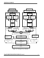
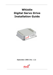
The EGOPS Concept is illustrated graphically in Figure 4-1.
WegCIGAMUG/ESA-EGOPSv52/SUM-OV, Issue 2
17
EGOPSv52 SUM-OV
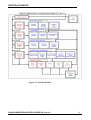
4.3.2 A View of the EGOPS Structure
The structural design of the EGOPS software can be best illustrated in terms of considering how the
software is partitioned into high-level modules, i.e., in taking an implementation-oriented view of the
entire tool. The implementation-oriented view is illustrated in Figure 4-2.
The entire software is can be understood to be composed of a series of high-level modules with
specific dataflow between the modules.
The structure contains at highest level a "Project Selection" and a "Help Provision" module.
The rationale behind "Project Selection" is the following: EGOPS work and related data are organized
in "projects" (handled at User I/F level via a "Project" menu), which provide the user with a convenient
means to group the computations of a series of simulation scenarios, which for some logical reason
belong to each other, into a common folder. A "Project" within EGOPS is thus a group of simulation
and visualization/ validation activities whose data (input/output of simulation scenarios) is separated
from that of other projects.
In fact the separation of the projects is physically reflected in the EGOPS file structure on disk, where
each project's data are gathered below a ./projects/<project-id> subdirectory which is created as
subdirectory of the root directory ../EGOPS during project launch. (See the subsection on "File
structure" below.)
The rationale behind on-line "Help Provision" for all EGOPS functions, both at main User I/F level
and at sub-levels (window-based help within each pop-up User I/F window), is obvious: It is more
convenient to work if one needs not necessarily refer to written documentation in course of using a
software.
Furthermore, the structure contains a bulk of four modules named "...Input" and a bulk of five "Tasks".
Each of the first four "Task" has an associated "Input" module. These first four "Tasks", the "Mission
Analysis/Planning", the "Forward Modeling", the "Observation System Modeling", and the
"Inversion/Retrieval", constitute the computational kernel of EGOPS in that these are actually
performing the end-to-end occultation simulations whilst the last "Task", the "Visualization/Validation
Function", is devoted to post-processing and validation processing and especially to conveying the
results produced by the four computational "Tasks" in convenient form to the User.
The possible dataflows among the modules reflect the natural hierarchy of the physics the software
deals with (as further detailed below within the following subsections and also well seen in the
graphical illustration; Figure 4-2).
WegCIGAMUG/ESA-EGOPSv52/SUM-OV, Issue 2
18
EGOPSv52 SUM-OV
REAL WORLD
MODEL WORLD
User Input Parameters
Quantities Expressing State
of Real World Considered
Tx Signal
Parameters
Tx Signals
Forward
Modeling
Atmosphere/
Ionosphere
System
Simulator
Occultation
Geometry
Geometry
Simulator
Atmosphere/
Ionosphere
Signal
Propagation
Simulator
Signal
Propagation
Tx-Rx
System
Simulator
Tx-Rx
System
Simulated
Signal
Simulated
Geom. Data
Signal
Propagation
Observed
Geom. Data
∪
Observed
Signal
∪
OR
Pool of Basic Simulated & Observed Parameters
Data Extraction
Modules
Inversion/Retrieval
Toolkit
Final Pool of Radio Occultation Data Products
Simulated
Atmosph./Ionosph.
Data
Post-Processing/Reference
Data Provision
Toolkit
Real Measuring
Instruments
Observed
Atmosph./Ionosph.
Data
Visualization/Validation
Toolkit
Figure 4-1: Conceptual View of EGOPS
WegCIGAMUG/ESA-EGOPSv52/SUM-OV, Issue 2
19
EGOPSv52 SUM-OV
Figure 4-2: EGOPS Modules
WegCIGAMUG/ESA-EGOPSv52/SUM-OV, Issue 2
20
EGOPSv52 SUM-OV
4.3.3 Main Objectives and Features of EGOPS
Mission analysis/planning, RO (RR) observation simulations, and RO (RR) data processing form the
computational core of EGOPS. Complementing this, integrated visualization/validation capability,
including post-processing, is provided.
To serve all these needs in an end-to-end framework adopted for EGOPS, the computational core is
partitioned into mission analysis/planning, forward modeling, observation system modeling, and
inversion/retrieval. Visualization and validation capability, with integrated post-processing functions, is
added supporting the analysis and interpretation of studies performed with each of the computational
parts. This partitioning just leads to the EGOPS Tasks and Inputs to Tasks for the computational parts.
The high-level structural components are further explained below.
Mission Analysis/Planning (MAnPl): This component comprises the analysis and planning of
satellites/constellations carrying receivers, including antennae field-of-view planning and analysis and
visibility analysis with respect to ground stations, for assessing, investigating, and optimizing
occultation event coverage and related relevant statistics.
Main parts for mission analysis and planning are simulation of occultation (reflection) geometries
("Geometry Simulator") and computation of the visibility of satellites from ground fiducial or tracking
sites ("Visibility Information Generator").
Forward Modeling (FoMod): Forward Modeling (FoMod), together with subsequent Observation
System Modeling (OSMod), performs simulation of observables, and related required variables, of the
radio occultation technique. The main observables are time-tagged phase and amplitude measurements.
Forward Modeling itself denotes the simulation of the signal propagation through the
atmosphere/ionosphere given the orbital motions of the transmitter and receiver satellites. It results in
"ideal" signals which contain the effects of the atmosphere/ionosphere media only. Thus FoMod results
allow to inspect the environmental influence alone.
Main parts for forward modeling are orbit arcs simulation for transmitter and receiver for the period of
the occultation events treated ("Orbit Arcs Simulator"), simulation of the atmosphere/ionosphere
("Environment Simulator"), and propagation simulation (ray tracing) for the radio link ("Signal
Propagation Simulator").
Observation System Modeling (OSMod): OSMod, following FoMod and using its "ideal" signal and
orbit arcs output data, denotes the superposition of all sorts of relevant physical and technical
influences of the observation system (antenna, receiver, platform, fiducial sites) on the "ideal" signal
(phase and amplitude data) arriving at the receiving antenna, and on the "ideal" orbit data (transmitter
and receiver positions and velocities). In fact these "ideal" data are the output of Forward Modeling, a
necessary prerequisite to be performed before Observation System Modeling can be done.
The most relevant observation system effects to be modeled include precise orbit determination (POD)
errors, the antennae gain pattern, receiver noise, local multipath (due to the platform structure in the
vicinity of the antenna), and differencing treatment/clocks precision.
The main parts for observation system modeling are precise orbit determination (POD) error simulation
("POD Error Simulator"), antennae pattern simulation ("Antennae Simulator"), and receiving system
simulation ("Receiving System Simulator"), the latter including modeling of receiver performance,
local multipath, and differencing treatment/clocks.
WegCIGAMUG/ESA-EGOPSv52/SUM-OV, Issue 2
21
EGOPSv52 SUM-OV
Occ. Data Inversion/Retrieval (InRet): Inversion/Retrieval processing is the last computation stage of
end-to-end simulations. In addition, besides processing of simulated data, it is applicable in an identical
manner also to observed data (e.g. from the GPS/MET or CHAMP experiment). More specifically, the
InRet function performs the processing of simulated or observed phase and amplitude data
(supplemented by the necessary geometrical information) typically via Doppler shifts and bending
angles down to quasi-vertical atmospheric profiles of refractivity, density, pressure, temperature, and
humidity. EGOPS also allows to process ionosphere profiles of total electron content, Doppler shift,
bending, refractivity, and electron density.
This processing chain typically requires, sequentially, tools for ionospheric correction and conversion
of the "raw" excess phase observables to neutral-atmospheric bending angle profiles, for inversion of
bending angle profiles into refractivity profiles ("Inverse Abel Transform"), and for finally retrieving
the atmospheric variables (e.g., temperature) from refractivity. The air (in the troposphere) may be
considered either dry or moist in the last stage of this processing chain.
The main parts are for occultation data inversion/retrieval are, based on the processing chain outlined,
an "Ionospheric Correction and Bending Angle Retrieval Toolkit", a "Refractivity Profiles Retrieval
Toolkit", and an "Atmospheric Profiles Retrieval" Toolkit".
User I/F and post-processing, visualization and validation: From the point of view of the EGOPS User
I/F, there is a "Task" menu available at main level, which furnishes four generic Task options, i.e.,
menu entries. These correspond directly to the four main computational parts (MAnPl, FoMod,
OSMod, and InRet) outlined above. Thus the simulator fully reflects the natural hierarchy of the
simulation problem and the results of one task the User performs (e.g., a MAnPl task) are typically part
of the input of the next-stage task (e.g., a FoMod task). (Briefly on what EGOPS "tasks" are: these are
the individual computational scenarios comprised by an EGOPS Project. A task corresponds to
computing a specific scenario by employing one of the four generic Task options.)
The link between the "Task" menu entries and the computational parts is provided by the four modules
"MAnPl Input", "FoMod Input", "OSMod Input", and "InRet Input", which correspond to four User I/F
window interfaces, each one accessed by a specific "Task" menu entry. These Input modules directly
supply the User input data to their respective computational Task.
After any stage, post-processing and visualization/validation is possible for the results so far computed,
by employing the EGOPS "Visualization/Validation Function", which corresponds, at User I/F level, to
the "Visualize/Validate" menu. The components of this are "ManPl Profiles", "Geographic Maps",
"Profiles", "Volume Data", and "Data Animation" (Note: The latter two modules compute and visualize
atmosphere/ionosphere field variables rather than simulated/processed results). These modules, in turn,
correspond at User I/F level to five window interfaces, each one accessed by a specific
"Visualize/Validate" menu entry.
For each of the four generic Task options, the User is furnished a specific single input window (e.g.,
MAnPl Input I/F window) providing for input of all necessary parameters for any desired individual
computation scenario (task), and including the option of loading already existing tasks.
(Note: within a project often scenarios are analyzed differing only in one or very few parameters in
their input. In this case the respective individual task input data are very similar and loading of existing
task input data can immediately provide a very good default for a next task.)
WegCIGAMUG/ESA-EGOPSv52/SUM-OV, Issue 2
22
EGOPSv52 SUM-OV
4.3.4 The Two Programming Language Approach of EGOPS
The use of two programming languages was constrained by the facts
(i) that the EGOPS User Interface and Visualization functionality should be user-friendly (windowdriven, point-and-click, effective visualization), and
(ii) that several computational routines existed in FORTRAN-77, which were worth including in an
adapted form within EGOPS.
Constraint (i) called for a powerful high-level language. IDL (Interactive Data Language) was selected,
which is widely in use in the engineering/scientific world for interactive visual analysis applications as
EGOPS can be considered to be one.
Constraint (ii) called for use of FORTRAN for the computational modules. FORTRAN-95 was
selected, which is downward compatible to F77, which is widely in use in the engineering/scientific
world for mathematical routines. The choice of FORTRAN-95 ensures that newly developed EGOPS
software can follow the state-of-the-art FORTRAN, while all existing FORTRAN-77 software is still
readily included.
EGOPS is an IDL/FORTRAN software product with the GUI modules written in IDL and all
computational Tasks (MAnPl, FoMod, OSMod, and InRet) are written in FORTRAN.
The data exchange, from input data to result data, within the IDL and FORTRAN part of EGOPS is
performed via files (see the subsection below). This completely avoids any call of FORTRAN within
IDL and vice versa. With respect to the usage of OS commands within EGOPS, generic Solaris/Linux
commands are avoiding dependence on a specific Solaris/Linux dialect, implementation or platform.
Control is exercised by IDL and the interfacing between IDL and FORTRAN is as follows.
An IDL module (e.g., the "MAnPl Input" User I/F after commanding "Compute") generates an input
file for its respective computational task and then kicks off execution of the FORTRAN executable.
The task’s main program then reads the complete set of input data from the input file and performs the
computations for the given scenario task according to the input. In parallel, it outputs the status of the
computations to task’s log file. The current settings of a task’s input file can be inspected by pressing
the “View Input” button at the bottom of the task’s main window.
Result files are then produced by specific task modules. (Note: In the "EGOPS Modules" Figure 4-2 the
result file dataflows are indicated by the vertical arrows from one computational task to the next and by
the arrows, at the right part of the Figure, towards the Visualization/Validation Functions.)
Having resumed back control, the IDL interface checks the log file for the termination status of the
computation and announces successful or failed completion. For viewing the log file, press the button
“View Log” next to the “View Input” button.
WegCIGAMUG/ESA-EGOPSv52/SUM-OV, Issue 2
23
EGOPSv52 SUM-OV
4.3.5 File Structure Behind EGOPS
All EGOPS programs and data are placed under a root directory named ../EGOPS during the
installation process. EGOPS.Run or EGOPS.RunVM are the command files, which are executed to start
EGOPS.
Below the EGOPS installation directory, the file structure consists of two main parts. One part holds the
project-independent data of EGOPS, the other part holds the project-related data, which are partitioned
according to the four generic Task options available (MAnPl, FoMod, OSMod, InRet).
There is one project which is integral to EGOPS, named "EGOPSProject", which is associated with the
..projects/EGOPSProject subdirectory in the file structure. It belongs to the basic installation package,
and is the default project of EGOPS which contains the minimal default information necessary to
operate the simulation and visualization/validation functionality. (Each time a new project is started,
this minimal default information is carried over from the "EGOPSProject" to the new project's
directories.)
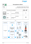
The EGOPS file structure is listed and explained in the following figure:
EGOPS:
drwxr-xr-x
-rwxr-xr-x
-rw-r--r--rw-r--r--rwxr-xr-x
-rwxr-xr-x
-rwxr-xr-x
drwxr-xr-x
drwxr-xr-x
drwxr-xr-x
drwxr-xr-x
drwxr-xr-x
drwxr-xr-x
drwxr-xr-x
drwxr-xr-x
drwxr-xr-x
drwxr-xr-x
EGOPS/bin:
drwxr-xr-x
drwxr-xr-x
drwxr-xr-x
.
EGOPS.cmd
EGOPS.ReadMe
EGOPS.Revision
EGOPS.Run
EGOPS.RunDV
EGOPS.RunVM
AtmoIonoData
ObservedData
projects
projshelf
bin
src
help
genPSfiles
referdata
settings
.
bin_Linux
bin_Solaris
EGOPS main directory
start script for running EGOPS computations w/o GUI
file with EGOPS packaging, setup and use notes
Version Control Information file
start script for running EGOPS GUI (1)
start script for compiling EGOPS GUI components (1)
start script for running EGOPS GUI via IDL-VM (2)
directory for Atmosphere or Ionosphere model data (3)
directory for observed RO data (3)
directory for each EGOPS project's subdirectory (4)
directory for storing archived EGOPS projects
directory containing the EGOPS binaries/executables (5)
directory containing the EGOPS source code
directory containing the EGOPS online help files
directory for PS files generated by EGOPS print functions
directory for volume- and map-based data of RefDataProv.x
directory containing EGOPS configuration data
directory containing precompiled binaries for Linux OS
directory containing precompiled binaries for Solaris OS
EGOPS/referdata:
drwxr-xr-x .
drwxr-xr-x mapsdata
drwxr-xr-x volumdata
directory for map-based data of RefDataProv.x
directory for volume-based data of RefDataProv.x
EGOPS/settings:
drwxr-xr-x .
-rw-r--r-- EGOPS.ini
-rw-r--r-- EGOPSProject.tar.gz
drwxr-xr-x antpattern
drwxr-xr-x groundst
drwxr-xr-x MSIS_CIRA
drwxr-xr-x orbitelem
drwxr-xr-x signalprop
configuration file for various EGOPS user defaults
default project required by EGOPS GUI for initialization
directory for antenna pattern files (*.apd, *.apdr)
directory for groundstation location files (*.gst)
directory for MSIS and CIRA atmosphere model parameters
directory for satellite orbital element files (*.tle)
directory for TX satellite signal properties (*.spd)
WegCIGAMUG/ESA-EGOPSv52/SUM-OV, Issue 2
24
EGOPSv52 SUM-OV
EGOPS/src:
drwxr-xr-x
drwxr-xr-x
drwxr-xr-x
-rwxr-xr-x
drwxr-xr-x
drwxr-xr-x
drwxr-xr-x
drwxr-xr-x
drwxr-xr-x
drwxr-xr-x
drwxr-xr-x
drwxr-xr-x
drwxr-xr-x
.
base
config
configure
external
fftw
filib
gcm
grib
gui
include
lib
wavelib
directory containing the EGOPS source code
directory of the computational FORTRAN and C source code
directory containing files for the build system
script for compiling the computational routines (*.x)
directory for external libraries, e.g. netCDF and RFM
directory for the MIT FFT library
directory for the IAP forward/inverse routines library
directory for the GCM library
directory for the GRIB library
directory for the EGOPS GUI's IDL source code
directory containing include files for the build system
directory containing library files for the build system
directory for the IAP WaveOptics library
EGOPS/src/config/flags:
drwxr-xr-x .
directory containing the compiler specific flag files
EGOPS/src/config/flags_unsupported:
drwxr-xr-x .
directory with unsupported compiler specific flag files
EGOPS/src/external:
drwxr-xr-x .
-rw-r--r-- netcdf_stub.for
-rw-r--r-- netcdf.tar.gz
-rw-r--r-- rfm.diff
-rw-r--r-- rfm_stub.for
-rw-r--r-- rfm.tar.gz
stub file for netCDF, if no netCDF source is available
netCDF v3.6.1 source code (6)
patch file with the EGOPS-related modifications to RFM
stub file for RFM, if no RFM source code is available
RFM source code (7)
(1)
requires full IDL development license
(2)
does not require IDL development license
(3)
any EGOPS *.inp file referencing this directory will store the filepath releative to
the EGOPS installation directory (useful when exchanging projects between different
users or computers)
(4)
each EGOPS project directory contains four subdirectories for the basic EGOPS task
groups, namely MAnPl, FoMod, OSMod and InRet. Within these subdirectories, the task's
run control files (*.inp) and the associated output files are stored.
(5)
these are: EGOPS.sav (GUI's IDL save file), MAnPl.x , FoMod.x, OSMod.x, InRet.x,
RefDataProv.x and CreateTLE.x
(6)
netCDF source code may be obtained from: http://www.unidata.ucar.edu/software/netcdf/
(7)
RFM source code may be obtained from: http://www.atm.ox.ac.uk/RFM/
Figure 4-3: EGOPS File Structure
WegCIGAMUG/ESA-EGOPSv52/SUM-OV, Issue 2
25
EGOPSv52 SUM-OV
Project-related part of the file structure:
Concerning the project-related part, each User-specified project, as soon as launched via the EGOPS
User I/F by assigning a Project-id (name), is allocated its own directory (directories ../projects/<projectid1>/, ../projects/<project-id2>/, etc.). (Note that the ../projects/EGOPSProject directory always exists.)
A project directory contains all the information related to it in subdirectories named according to the
four generic Task options available (subdirectories /MAnPl, /FoMod, /OSMod, and /InRet). In any
project directory a <project-id>.txt file exists, which the User may utilize as "notebook" to protocol
information on the project. (Note that EGOPSProject.txt contains information on its own rationale
which must not been touched.) A project can be closed, opened, and renamed at any stage of work
without impairing the existing information conserved in its file structure.
The four "Task option" subdirectories contain the respective input files for handling User I/F (IDL)
information to the computational Tasks (FORTRAN), one unique file for each specific scenario (task)
computed by the User and thereby assigned a task-id. These files are the <task-id>.inp files, which exist
in the "Task option"-subdirectories (/MAnPl/<task-id.MA1>.inp,
/FoMod/<task-id.FM1>.inp, etc.).
The "Task option" directories furthermore hold all result files produced by the respective computational
Tasks as explained below.
MAnPl directory:
In case of MAnPl these are, for each individual task performed, a "Occultation Event Geometry Data"
file (/MAnPl/<task-id>.egd) or a "Reflection Event Geometry Data" file (/MAnPl/<task-id>.rgd) and,
optionally, a "Visibility Data" file (/MAnPl/<task-id>.vis). The /MAnPl directory will also contain all
ManPl "child"-files derived during post-processing for visualization (e.g., histogram data).
FoMod directory:
In case of FoMod these are one or more "Signal Geometry Data" file(s) (/FoMod/<task-id>_<occno>.sgd; containing the "ideal" FoMod geometry data) and one or more "Signal Source Data" file(s)
(/FoMod/<task-id>_<occ-no>.ssd; containing the "ideal" FoMod phase and atmospheric power loss
data). One file per simulated occ. event exists. The number of occ. events depends on the event sample
size chosen by the User for the given task. The basic space/time information on the occurrence of the
occultation events is taken from a /MAnPl/<task-id>.egd file prepared by an earlier MAnPl task run
(selected during FoMod input). The directory will also contain all FoMod "child"-files which may be
derived in course of the visualization/validation processing from the "ideal" signal data.
OSMod directory:
In case of OSMod these are one or more "Signal Geometry Data" file(s) (/OSMod/<task-id>_<occno>.sgd; containing the quasi-realistic geometry data) and one or more "Signal Source Data" file(s)
(/OSMod/<task-id>_<occ-no>.ssd; containing the quasi-realistic excess phase and amplitude data). One
file per simulated occ. event per file. The number of occ. events depends on the event sample size
chosen by the User for the given task. The basic event samples for superposition of observational
effects, both *.sgd and *.ssd files, are taken from /FoMod/<task-id>_<occ-no>.sgd(.ssd) file samples
WegCIGAMUG/ESA-EGOPSv52/SUM-OV, Issue 2
26
EGOPSv52 SUM-OV
prepared by an earlier FoMod task run (selected during OSMod input). The directory will also contain
all OSMod "child"-files which may be derived in course of the visualization/validation processing from
the quasi-realistic signal data.
InRet directory:
In case of InRet the subdirectory ../projects/<ProjectId>/Data) provides, for both simulated and
observed RO data processing, directories tailored to the derived data products, e.g. Doppler shifts
(/Dopp), bending angles (/Bend), refractivities (/Refr), densities (/Dens), pressures (/Pres), temperatures
(/Temp), water vapor (/WVap), total electron content (/ITec) or /PhAm, which contains the duplicated
input or the back-propagated phase and amplitude data. These contain the respective result files, one
file per occ. event, from the InRet task. The basic result profiles are contained in <task-id>_<occno>.<Par> files, where <Par> denotes one of "Dopp", "IDop", "Bend", "IBen", "Refr", "IRef", "Dens",
"IDen", "Pres", "Temp", "Wvap", "Humi", "ITec" etc.; "WVap" (water vapor pressure) and "Humi"
(specific humidity) which are both contained in the /WVvap directory. The respective directories
contain as well all the "child"-files, which may be derived from the basic result profiles of the
parameters in course of the visualization/validation process.
For observed data processing (EGOPS GPS/MET or CHAMP data processing), where the original data
(profiles of RO observables) reside in a file structure external to EGOPS or in ../EGOPS/ObservedData/
(as the "EGOPS File Structure" Figure indicates), the subdirectory /PhAm holds the duplicated
observed geometry and signal data (files /PhAm/<task-id>_<occ-no>.sgd and /PhAm/<task-id>_<occno>.ssd, respectively) in the EGOPS-internal geometry and signal data format.
The basic data for computation are taken by the InRet task, in case of simulated data, from
/OSMod/<task-id>_<occ-no>.sgd(.ssd) file samples prepared by an earlier OSMod task run (selected
during InRet input). In case observed data are processed, the basic data (level-2 data) are taken from the
respective data directory assigned by the User (during InRet input).
WegCIGAMUG/ESA-EGOPSv52/SUM-OV, Issue 2
27
EGOPSv52 SUM-OV
4.3.6 Batch Processing and Project Archiving with EGOPS
Batch Processing Functionality of EGOPS
EGOPS provides beside the usual interactive computing capabilities a Batch Job Facility for time
consuming computations, e.g., specific Forward Modeling (FoMod) or Inversion Retrieval (InRet)
Tasks. EGOPS Batch Jobs can be scheduled to start immediately or at a User specified time instance by
activating the "Batch ..." button, which is generally positioned besides the "Compute ..." button.
Clicking this button will pop up a dialogue window that allows the User to specify the desired start time
& date of the EGOPS batch job. Furthermore, using the related button “Batch Jobs Info...”, the User can
check the status of previous EGOPS batch job requests, terminate running or pending jobs, remove a
task from the Batch Processing Information window or remove all finished tasks from the Batch
Processing Information window. EGOPS does not support "Batch Job Chain Processing" for stacking
job requests. It is the responsibility of the User to properly specify the start times of inter-dependent
jobs.
EGOPS Project Archiving and Restoring
In order to save disk space or to allow an easy transfer of whole projects (i.e., of all data of an EGOPS
Project), EGOPS provides a project archiving function. The project intended for archival will be put
into a gzip’ed tar-archive file in the ../EGOPS/projshelf directory. Any shelved project file can be
restored by using the EGOPS project restore function. Both shelving and restoring are accessible via
entries in the “Project” Menu at the main level of the EGOPS User I/F.
WegCIGAMUG/ESA-EGOPSv52/SUM-OV, Issue 2
28
EGOPSv52 SUM-OV
4.4 Mission Analysis/Planning
GENERAL DESCRIPTION
Mission Analysis/Planning (MAnPl) is considered to include the analysis and planning of satellite
constellations carrying receivers, including antennae field-of-view planning and analysis and visibility
analysis with respect to ground stations, for assessing, investigating, and optimizing occultation event
coverage and related relevant statistics. EGOPS includes also reflection data calculation scenarios
whereby the reflection medium is a water surface (normally the ocean or several huge lakes) that like a
big mirror for reflecting the transmitted radio signals to the receiver satellite.
Such analysis requires a considerable number of "free input parameters" in a simulation tool in order to
allow for a realistic MAnPl. (See the section "MAnPl INPUT PARAMETERS" below for an overview
on the respective functionality furnished by EGOPS.)
Furthermore, it is necessary to have convenient tools for visualization of the simulation results available
in order to carry out simulation studies efficiently and in order to effectively comprehend and interpret
the results. (See the section "MAnPl VISUALIZATION" below for an overview on the respective
functionality furnished by EGOPS.)
MAnPl INPUT PARAMETERS
EGOPS allows to compute Mission Analysis/Planning tasks taking into account the set of "free input
parameters" outlined below. The "MAnPl Input" window, available via the "Mission
Analysis/Planning" entry of the "Task" menu, is the interface EGOPS provides for the supply of all of
these.
- Data type Selection:
Occultation or Reflection data calculation for GNSS-LEO or LEO-LEO constellations can be selected.
The User I/F changes for the different data types. For Reflection data selection the specular points at the
ocean surface are calculated at user selected time steps. For Occultation data selection the satellite
occultations are calculated at the desired height levels.
- Simulation time:
Start date and time, and the total time range for a simulation.
- Height levels of interest:
For each of such height levels (and for each occultation in the time range) the corresponding occultation
geometry is computed, interpreting the height levels as those tangent point heights of an occultation
event for which the geometric information is sought just at the instant when the levels are crossed. The
essential geometric information is the corresponding geographic coordinates of the tangent point
together with the corresponding positions of the transmitter and receiver satellites involved in the
occultation event. Height levels are only used for calculation of occultation data.
- Time steps:
WegCIGAMUG/ESA-EGOPSv52/SUM-OV, Issue 2
29
EGOPSv52 SUM-OV
Choose an integer divide of the simulation time range for the reflection data time step. Time steps are
only used for reflection data calculation. For each time step the coordinates of the specular point at the
ocean surface are computed.
- Geographic area of interest:
Global, hemispheric, or any regional area for which the coverage by occultation or reflection events is
sought.
- Tx-to-Rx/Reflection ray treatment:
Straight-line approximation of rays, or rays with quasi-realistic bending caused by the neutral
atmosphere.
- Earth Figure model:
Spherical (R=6371km) or Ellipsoidal (WGS-84) Earth.
- Tx and Rx antenna specifications:
Antennae pointing and characteristics, including boresight direction and field-of-view width and shape,
for "anti-velocity" looking and forward-looking antenna.
-Rx zenith antenna:
Zenith antenna elevation limit.
- Passive space segment / Rx satellite System:
Orbit constellation (i.e., orbit elements) of receiver platforms. This information is supplied by the *.tle
files in the ./orbitelem directory.
- Tx and Rx orbit propagator:
Spherical orbit approximation, Keplerian orbit, or "Simplified General Perturbation (SGP)" orbit (the
latter including short and long period perturbations and parameterized atmospheric drag).
- Active space segment / Tx Satellite System:
Orbit constellation (i.e., orbit elements) and signal property definition of the transmitter platforms.
GPS, GLONASS and GALILEO (in case of GNSS-LEO) or ACE (in case of LEO-LEO) setup are
available. This information is supplied by the *.tle and *.spd files in the ./orbitelem and ./signalprop
directories of EGOPS.
- Ground segment (Fiducial and Tracking sites):
The number, location, and antenna field-of-view of auxiliary earthbased receiver sites for aiding the
usual single- or double-difference processing of occultation data (fiducial sites), and the location, and
antenna field-of-view of ground stations for telemetry/telecommand (tracking sites). This information is
supplied by fid*.gst and trk*.gst files, respectively, in the ./groundst directory of EGOPS, which are
selected within the "MAnPl input" window. Satellite visibility information is then computed for the
fiducial and tracking stations, as necessary for assessing the visibility conditions for single- and/or
double-differencing and tracking for a given scenario.
MAnPl VISUALIZATION
WegCIGAMUG/ESA-EGOPSv52/SUM-OV, Issue 2
30
EGOPSv52 SUM-OV
EGOPS provides for the visualization of results of Mission Analysis/Planning tasks by its "Visualize
MAnPl Statistics" and "Visualize Geographic Maps" window interfaces, both available through the
"Visualize/Validate" menu. The "MAnPl Statistics" interface allows to compute, visualize, and printout 1D and 2D occultation (reflection) coverage statistics as function of variables like latitude, Local
Time, Duration of occultation Events, etc. Furthermore, it allows to compute, visualize, and print-out
visibility statistics for fiducial and tracking sites, e.g., no. of occultation events for which successful
single- or double-differencing is possible by each of a given sample of fiducial sites, or no. of orbits
seen for a certain time range per orbit by each of a couple of tracking sites. Additionally it is also
possible to display a global statistics in latitude and longitude bands about number of events per area,
mean distances and rms of mean distances, or time separations and rms of time separations between
events.
The "Geographic Maps" interface allows to compute, visualize, and print-out latitude-longitude maps
(different map projections available) of occultation and reflection event coverage for arbitrary
geographic areas and including information such as on the geometrical shape and time of each event.
Furthermore, it allows to compute, visualize (stand-alone or as overplot to occultation event coverage
maps), and print-out geographic maps of a series of atmospheric/ionospheric variables (e.g.,
temperature and electron density) from all atmospheric/ionospheric models available within EGOPS.
These may either slice the atmospheric/ionospheric field at a certain height or be vertically integrated
quantities (e.g., total precipitable water).
WegCIGAMUG/ESA-EGOPSv52/SUM-OV, Issue 2
31
EGOPSv52 SUM-OV
4.5 Forward Modeling
GENERAL DESCRIPTION
Forward Modeling (FoMod), together with subsequent Observation System Modeling (OSMod),
performs simulation of observables, and related required variables, of the radio occultation technique.
The main observables are time-tagged phase and amplitude measurements, obtained in real world by
tracking occulted transmitter signals with a LEO or Airborne platform mounted receiver for
atmospheric sounding during their set/rise through the atmosphere imposed by the relative orbital
motion of the transmitter and receiver satellites or the tracks of airborne receivers.
Forward Modeling itself denotes the simulation of signal propagation through the
atmosphere/ionosphere given the orbital motions of the transmitter and receiver satellites or airborne
receivers. It results in "ideal" signals which contain the effects of the atmosphere/ionosphere media
only. - "Ideal" in the sense that it is the state of the signal right before it enters the receiving antenna
and before any degradations by the receiving system are incurred. Thus FoMod results allow to inspect
the environmental influence alone.
Furthermore, it is quite useful in terms of computational performance to separate FoMod, involving
CPU-expensive propagation simulation (i.e., ray tracing) from OSMod, since the latter can be treated
very efficiently as superposition of "observation system" effects on the "ideal" signal. Thus studies of
different receiving system effects can be efficiently carried out using one and the same CPU-expensive
FoMod results as baseline.
In case of interest in observation simulations, Forward Modeling is the natural stage in EGOPS
following some planning and preparation of occultation events with desired properties within "Mission
Analysis/Planning (MAnPl)" (e.g., events occurring in a geographic region of interest, etc.). In fact the
geometric properties (i.e., transmitter and receiver orbital arcs) of an occultation event being "forward
modeled" can be, in case simulations are desired for realistic geometry, directly taken from the results
of a User-selected MAnPl task. In contrast to the spaceborne case, the geometry analysis of airborne
occultation simulations is prepared in a FoMod-PopUp-Window directly. Forward modeling requires a
considerable number of "free input parameters" in a simulation tool in order to allow for a (realistic)
FoMod simulation of widely arbitrary occultation missions. (See the section "FoMod INPUT
PARAMETERS" below for an overview on the respective functionality furnished by EGOPS.)
Furthermore, it is necessary to have convenient tools for visualization and validation of the simulation
results available in order to carry out simulation studies efficiently and in order to effectively
comprehend and interpret the results. (See the section "FoMod VISUALIZATION" below for a crude
overview on the respective functionality furnished by EGOPS.)
WegCIGAMUG/ESA-EGOPSv52/SUM-OV, Issue 2
32
EGOPSv52 SUM-OV
FoMod INPUT PARAMETERS
EGOPS allows to compute Forward Modeling tasks taking into account the set of "free input
parameters" outlined below. The "FoMod Input" window, available via the "Forward Modeling" entry
of the "Task" menu, is the convenient interface EGOPS provides for the supply of all of these
parameters (including the supply of a "Reference MAnPl Task-id" in case simulations are desired for
realistic geometry, providing for access to the input conditions and results of a prior MAnPl task).
- Type of occultation event to be simulated: A single event or a whole sample of events can be „forward
modeled“, whereby single events (spaceborne or airborne) can be simulated either for an ideal
geometry (assuming co-planar transmitter and receiver orbits/trajectories and, correspondingly,
virtually-vertical tangent point trajectory) or for a realistic geometry (based on the geometry data
obtained for a result event of a prior MAnPl task). Sample-of-event simulations (spaceborne only)
always require event samples from a prior MAnPl task.
- Specifications for modeling a single event with ideal geometry: Tangent point location, azimuth of
occultation plane (containing transmitter, receiver, and the Earth’s center), start date and time,
transmitter and receiver satellite orbital heights or aircraft flight altitudes, and height range over which
the occultation event shall be „forward modeled“.
- Specifications for modeling with realistic geometry: Reference MAnPl Task-id (to be selected from
the list of suitable MAnPl tasks existing within the current Project in case of a spaceborne occultation
event), event number of desired event within the MAnPl results (if single event) or event number range
within the MAnPl results (if sample of events), and height range over which the event(s) shall be
„forward modeled“.
- Choice of atmospheric and ionospheric models:
- Climatological atmospheric model: No atmosphere, or simple dry or moist (bi-)exponential
atmosphere, or dry 3D atmosphere, or dry or moist 2D atmosphere, or the GSM 3D Atmosphere, or the
HiVRes Atmosphere.
- Atmospheric turbulence model: No turbulence, or IEP turbulence model (available with the Q3D- and
Full3D- raytracers) or IAP turbulence model (available with the full Wave Optics propagator).
- Atmospheric disturbance model: No disturbance, or gravity wave superposed, or frontal system
gradient superposed, or tropopause fold superposed, or atmospheric inversion superposed.
- Climatological ionospheric model: No ionosphere, or simple double-Chapman ionosphere, or full 3D
ionosphere.
- Ionospheric disturbance model: No disturbance, or traveling ionospheric disturbance (TID)
superposed, or ionos. gradient superposed, or ionos. trough superposed, or ionos.storm effect
superposed.
- Sampling rates for forward modeling: 2000 Hz, 1000 Hz, 500 Hz, 100 Hz, 50Hz, or 10 Hz, or 5 Hz, or
1 Hz, or 0.1 Hz.
WegCIGAMUG/ESA-EGOPSv52/SUM-OV, Issue 2
33
EGOPSv52 SUM-OV
- Signal propagation simulator:
Quasi-3D ray tracing (considering, in terms of refractivity gradients, the radial gradient only), full-3D
ray tracing (accounting for the full-3D refractivity gradient field), asymptotic wave optics propagation
or full wave optics propagation (for a more realistic computation dealing with diffraction and multipath
effects). Accuracy of ray-tracing can be set to <~ 1 mm, or <~ 1 cm, or <~ 10 cm (less demanding
accuracy allowing faster computations but yielding more inaccurate simulated phase observables) for
the first two signal propagation simulators whereas the accuracy for the wave optics propagators can be
set to be 'Basic', 'Advanced', or 'Highest'.
FoMod VISUALIZATION
EGOPS provides for the visualization of results of Forward Modeling tasks by its "Visualize/Validate
Profiles" window interface available via the "Visualize/Validate" menu.
The "Visualize/Validate Profiles" window interface allows, for FoMod tasks, to post-process, visualize,
customize, compare, and print-out simulated phase and amplitude data (in terms of
"atmospheric(/ionospheric) excess phase" and "atmospheric(/ionospheric) power loss") as function of
occultation event time.
The post-processing includes functionality to compute absolute and relative difference profiles between
profiles of different FoMod tasks or within a sample of events as well as profile statistics (mean and
standard deviation profiles) for samples of events.
- Customization includes, among other features, functionality to fit an exponential or polynomial of
user-specified order to a selected range of a profile or to compute the time average value over a selected
range of a profile (and to visualize this information by overplot on the original profile).
WegCIGAMUG/ESA-EGOPSv52/SUM-OV, Issue 2
34
EGOPSv52 SUM-OV
4.6 Observation System Modeling
GENERAL DESCRIPTION
Observation System Modeling (OSMod), together with prior Forward Modeling (FoMod), performs
simulation of observables and related required variables of the readio occultation technique. The main
observables are time-tagged phase and amplitude measurements.
Observation System Modeling itself denotes the superposition of all sorts of relevant physical and
technical influences of the observation system (antenna, receiver, platform, fiducial sites) on the „ideal“
signal (phase and amplitude data) arriving at the receiving antenna, and on the „ideal“ orbit/trajectory
data (positions and velocities). In fact these „ideal“ data are the output of Forward Modeling, a
necessary prerequisite to be performed before Observation System Modeling can be done.
Many of the effects of the observation system correspond to the „classical“ sort of instrumental errors
(e.g., receiver noise), others are intrinsic natural parts of the receiving system (e.g., effect of the antenna
gain pattern on the signal amplitude finally available). The most relevant observation system effects to
be modeled include precise orbit determination (POD) errors, the antennae gain pattern, receiver noise,
local multipath (due to the platform structure in the vicinity of the antenna), and differencing
treatment/clocks precision.
Observation system modeling requires a considerable number of „free input parameters“ in a simulation
tool in order to allow for a realistic OSMod simulation of widely arbitrary radio occultation missions.
(See the section „OSMod INPUT PARAMETERS“ below for an overview on the respective
functionality furnished by EGOPS.)
Furthermore, it is necessary to have convenient tools for visualization and validation of the simulation
results available in order to carry out simulation studies efficiently and in order to effectively
comprehend and interpret the results. (See the section „OSMod VISUALIZATION“ below for a crude
overview on the respective functionality furnished by EGOPS.)
OSMod INPUT PARAMETERS
EGOPS allows to compute Observation System Modeling tasks taking into account the set of „free
input parameters“ outlined below, which altogether provide considerable flexibility and potential for
Observation System Modeling. All these parameters can be - within their range of validity - freely set
by the User just as desired for a specific OSMod task. The „OSMod Input“ window, available via the
„Observation System Modeling“ entry of the „Task“ menu, is the convenient interface EGOPS provides
for the supply of all of these parameters (including the supply of a „Reference FoMod Task-id“,
providing for access to the input conditions and results of a prior FoMod task).
- Forward modeling occultation event(s) selection: Reference FoMod Task-id (to be selected from the
list of suitable FoMod tasks existing within the current Project). Also, in case a sample of events is
available for the selected Reference FoMod task, event number range (or individual event number) of
desired event(s) within the available FoMod events.
WegCIGAMUG/ESA-EGOPSv52/SUM-OV, Issue 2
35
EGOPSv52 SUM-OV
- Receiver sampling rates: OSMod sampling rates may be 2000 Hz, 1000 Hz, 500 Hz, 100 Hz, 50 Hz,
10 Hz, 5 Hz, 1 Hz.
- POD error modeling: No POD errors, or use a „kinematic“ POD error model. (The latter model
mimics POD position errors mainly by considering radial position errors, POD velocity errors by
considering along-ray velocity bias and drift errors (superposed to the „ideal“ receiver velocity), and
POD-induced excess phase errors by considering along-ray excess phase drift and acceleration errors
incurred by along-ray velocity bias and drift errors.)
- Occultation antennae specifications: Antennae pointing and pattern characteristics, including
boresight direction, field-of-view width and shape, and antenna gain at boresight (at 1 GHz), for
„anti-velocity“ looking and forward-looking antenna.
- Receiving system simulator type: Selection of either a Parameterized GNSS-LEO Receiver
Simulator or a Parameterizd LEO-LEO Receiver Simulator or a Realistic (GPS) Receiver System
Simulator is available.
For the Parameterized GNSS-LEO Receiver Simulator, the following GNSS-LEO Receiver specific
input parameters are available:
- GNSS Receiver performance/noise modeling specifications: No receiver noise, or Gaussian noise, or
realistic performance/noise can be selected, with the following specifications of the latter two:
- Gaussian noise model: RMS (root-mean-square) value of the Gaussian phase noise (thermal noise).
- Realistic performance/noise model: Loop bandwidth (single-sided), LEO antennae noise temperature,
and number of quantization levels in A/D conversion.
For the Parameterized LEO-LEO Receiver Simulator, the following LEO-LEO Receiver specific
input parameters are available:
- LEO Receiver performance/noise modeling specifications: No LEO-LEO Thermal Noise, LEO-LEO
Thermal Noise Model.
- LEO Receiver Drift Model: “No Polynomial Amplitude Drift Model”, “Polynomial Amplitude Drift
Model”; “No 1/f Ampl. Noise”, “1/f Ampl. Noise”; “No Sinusoidal Ampl. Drifts”, “Sinusoidal Ampl.
Drifts”.
- Local multipath modeling specifications: No local multipath, or sinusoidal local multipath, multiple
sines multipath, or realistic local multipath can be selected, with the following specifications of the
latter three:
- Sinusoidal multipath model: Period of the phase error, amplitude of the phase error, and
(initialization) amplitude of the phase error at the topmost height of the occultation event (a maximum
of 4 sines can be superposed).
- Multiple sines model: The same specifications as of the sinusoidal multipath model, but up to 4
individual sines can be chosen for calculation.
- Realistic multipath model: Ratio of multipath signal to direct signal, and source location (i.e.,
reflection point) of the multipath signal in (spherical) antenna coordinates.
WegCIGAMUG/ESA-EGOPSv52/SUM-OV, Issue 2
36
EGOPSv52 SUM-OV
- Differencing treatment and clocks modeling specifications: No differencing/perfect clocks, or no
differencing/real clocks, or double differencing, or ground-based single differencing, or spacebased
single differencing, with the following specifications of the latter four:
- No differencing/real clocks: Relative stability of GNSS clock (assumed the worst clock in case of no
differencing with real clocks involved).
- Double differencing: Relative stability of ground clock (assumed the worst clock in case of double
differencing), and atmospheric noise per ground-to-satellite link involved in the differencing (this noise
considered as clock-like noise).
- Ground-based single differencing: Relative stability of LEO clock (assumed the worst clock in case of
ground-based single differencing), and atmospheric noise per ground- to-satellite link involved in the
differencing.
- Space-based single differencing: Relative stability of LEO clock (assumed the worst clock in case of
space-based single differencing).
For the Realistic Receiving System Simulator, the following input parameters are available:
- GRAS Antenna Specifications – Antenna Pattern Files: It is possible to select between two different
antenna pattern files or user-supplied ones if available. Also the random number seed can be specified.
- Technical Specifications: Selection of System Noise Temperature, Number of interfering GPS
satellites, Implementation Loss, Antenna Internal Loss and Interference Misalign Loss can be set.
- Loop Specifications: Activation of Open Loop or Closed Loop Tracking (with Open Loop Tracking,
two atmospheric models are available), Loop Period Values and Start Time of 2nd Value are required.
- Frequency Locked Loop Specifications: Stop Time and Filter Order can be set.
- Filter Specifications: The technical specifications for the L1 and CA Filter are to be selected (Filter
Type and Filter Order, Bandwidth values and Start Time of 2nd Value).
OSMod VISUALIZATION:
EGOPS provides for the visualization of results of Observation System Modeling tasks by its
„Visualize/Validate Profiles“ window interface available via the „Visualize/Validate“ menu.
The „Visualize/Validate Profiles“ window interface allows, for OSMod tasks, to post-process,
visualize, customize, compare, and print-out simulated phase and amplitude data (in terms of „observed
excess phase“ and „observed power“, „observed“ here in the sense of end-to-end simulated
observables) as function of occultation event time. The excess phase data and LI data (ionosphere only
at 1st frequency) are available for visualization and inspection, stand-alone or in combinations.
The post-processing includes functionality to compute absolute and relative difference profiles bet-
WegCIGAMUG/ESA-EGOPSv52/SUM-OV, Issue 2
37
EGOPSv52 SUM-OV
ween profiles of different OSMod tasks or within a sample of events as well as profile statistics (mean
and standard deviation profiles) for samples of events.
Customization includes, among other features, functionality to fit an exponential or polynomial of
user-specified order to a selected range of a profile or to compute the time average value over a selected
range of a profile (and to visualize this information by overplot on the original profile).
WegCIGAMUG/ESA-EGOPSv52/SUM-OV, Issue 2
38
EGOPSv52 SUM-OV
4.7 Occultation Data Inversion/Retrieval
GENERAL DESCRIPTION
Inversion/Retrieval of occultation data denotes the processing of simulated or observed phase and
amplitude data (supplemented by the necessary geometrical information) typically via Doppler shifts
and bending angles down to quasi-vertical atmospheric profiles of refractivity, density, pressure,
temperature, and humidity.
This processing chain typically requires, sequentially, tools for ionospheric correction and conversion
of the „raw“ excess phase observables to neutral-atmospheric bending angle profiles, for inversion of
bending angle profiles into refractivity profiles („Inverse Abel Transform“), and for finally retrieving
the atmospheric variables (e.g., temperature) from refractivity. The air (in the troposphere) may be
considered either dry or moist in the last stage of this processing chain.
Another route of inversion (possible within EGOPS), directly leading from the raw observables to
refractivity, is „Inverse Fresnel Transform“: This method is CPU-expensive but exploits both phase and
amplitude observables to resolve small-scale structures in the troposphere (down to the 100 m level),
which are convolved in the observables due to atmospheric diffraction. For the „Inverse Abel
Transform“, the resolution is "diffraction-limited" at the "Fresnel-scale" (being somewhat less than 1
km in the Earth's troposphere).
Necessary prerequisites for inversion/retrieval are either simulated observables, obtained by
Observation System Modeling (OSMod) within EGOPS, or genuine observed phase and amplitude data
(e.g. from the GPS/MET, CHAMP, SAC-C or COSMIC experiment).
Such occultation data inversion/retrieval requires a considerable number of „free input parameters“ in a
simulation tool in order to allow for flexible data processing of widely arbitrary simulated radio
occultation missions as well as for observed data. (See the section „InRet INPUT PARAMETERS“
below for an overview on the respective functionality furnished by EGOPS.)
Furthermore, it is necessary to have convenient tools for visualization and validation of the simulation
results available in order to carry out simulation studies efficiently and in order to effectively
comprehend and interpret the results.
InRet INPUT PARAMETERS
EGOPS allows to process RO Data Inversion/Retrieval tasks taking into account the set of „free input
parameters“ outlined below. The „InRet Input“ window, available via the „Occ. Data Inv./Retrieval“
entry of the „Task“ menu, is the convenient interface EGOPS provides for the supply of all of these
parameters. An InRet task can either reference simulated data (supplied via a „Reference OSMod
Task-id“, providing access to the input conditions and results of a prior OSMod task), or, alternatively,
real data from one of the following RO missions: GPS/MET, SAC-C, CHAMP or COSMIC.
WegCIGAMUG/ESA-EGOPSv52/SUM-OV, Issue 2
39
EGOPSv52 SUM-OV
- Type of occultation data to be processed: Simulated data (prepared by prior OSMod tasks run within
EGOPS), or mission specific RO data from GPS/MET, SAC-C, CHAMP or COSMIC (provided by the
User in a directory to which at least read-access exists from the EGOPS installation).
- Occultation event(s) selection in case of simulated data: Reference OSMod Task-id (to be selected
from the list of suitable OSMod tasks existing within the current Project). Also, in case a sample of
events is available for the selected Reference OSMod task, event number range (or individual event
number) of desired event(s) within the available OSMod events.
- Occultation event(s) selection in case of observed: absolute data path (full directory path of the
directory where the desired observed data reside, e.g., /home/<usr>/gpsmet/level2/occ/95.294/) or
relative data path (e.g. ../ObservedData/ gpsmet/level2/occ/95.294/).
- Choice of Retrieval Processing Specifications: "General Atmospheric Processing" (default) for
General Phase/Power-to-Refractivity Processing, or "Ionosphere Processing", with the following
further choices:
- Choice of Bending Angle Retrieval Specifications: the following atmospheric bending angle retrieval
tools are available: “Basic Geom.Optics/Non Opt. Bend.Angle Retrieval”,
“Basic
Geom.Optics/Stat.Opt. Bend.Angle Retrieval”, “Advanced Geom.Optics Bend.Angle Retrieval”,
“Wave Optics Bend.Angle Retrieval Mk-1” and “Wave Optics Bend.Angle Retrieval Mk-2“, along
with the ionospheric bending angle retrieval tool termed “Standard Ionospheric Bend.Angle Retrieval”.
- Choice of Transmission Retrieval: for geometric optics processing, the transmission retrieval tool is
the “Standard Channel Transmission Retrieval” and for wave optics processing, the transmission
retrieval too is the “Wave Optics Transmission Retrieval”. The transmissions can then be either
processed directly as “Absolute Transmissions” or as “Differential Transmissions”.
- Refractivity Profiles Retrieval Specifications: For the Refractivity Profiles Retrieval/Inversion Tool,
”No Atmos. Refractivity Profiles”, “No Ionos. Refractivity Profiles”, “Abel Transform Refr. Profiles “,
Abel Transform Refr. + Absorption Coeff. Profiles”, and “Abel Transform Ionos. Refr. Profiles” are
possible selections.
- Profile retrieval tools for Atmospheric Processing are: “Refr. Based Dry Air Profiles”, “Refr. Based
Moist Air Profiles”, and “Refr. + AbsCoeff. Based Atmos. Profiles”.
- The profile retrieval tool in case of Ionosphere Processing is: “Elec.Density Prof. Retrieval”.
- For the type of “Refr. Based Moist Air Profiles” retrieval, prescribed and background parameters
can be specified: "q, e, p, rho, T prescribed (It)", "q, e, p, rho, T prescribed (In)", "q, e, rho with p, T
prescribed", "T, e, p, rho with q prescribed (In)", "T, e, rho with p, q prescribed" or "T, q, e, p, rho
by Optimal Estimation Retrieval". The later has the following input parameters: Observation and
Forward Modeling Error Covariance Matrix Specifications (with Refractivity RMS Uncertainty,
Vertical Correlation Length of Refractivity Errors) and Background (T, q) Error Covariance Matrix
Specifications (with Temperature and Humidity RMS Uncertainty, Vertical Correlation Length of
Temperature and Humidity Errors). The atmospheric model used for prescribed parameters can be:
"Bi-Exponential atmosphere", or "HLat 2D Atmosphere (CIRA86aQ_UoG)", or the "(Moist) GCM
3D Atmosphere (GCM3DAtm)", or "(Moist) HiVRes Atmosphere (HiVResAtm)".
WegCIGAMUG/ESA-EGOPSv52/SUM-OV, Issue 2
40
EGOPSv52 SUM-OV
- For the type of “Refr. + AbsCoeff. Based Atmos. Profiles” retrieval, the “Refractivity and
Absorption Coefficient Inversion Type”, the “Refractivity Error Model Choice”, the “Refractivity
RMS Error at zRef”, the “Absorption Coefficient Error Model Choice”, the “Absorption Coefficient
RMS Error Scale Factor”, the “Atmospheric Profile Retrieval Mode”, the “Atmosphere Background
Mode” and the “Atmosphere Model for best Fit” can be specified.
InRet VISUALIZATION
EGOPS provides for the visualization of results of Occ. Data Inversion/Retrieval tasks by its
„Visualize/Validate Profiles“ window interface available via the „Visualize/Validate“ menu.
The „Visualize/Validate Profiles“ window interface allows, for InRet tasks, to post-process, validate
against reference data, visualize, customize, compare, and print-out simulated or observed Doppler shift
profiles (as function of occ. event time), bending angle profiles (as function of impact parameter), and
refractivity, density, pressure, temperature, water vapor, and specific humidity profiles (as function of
height). Also, in case observed data, the original phase and amplitude data can be visualized (as
function of occ. event time).
The post-processing includes functionality to compute absolute and relative difference profiles between
profiles of different InRet tasks or within a sample of events as well as profile statistics (mean and
standard deviation profiles) for samples of events. Furthermore, reference „ground-truth“ profiles of
refractivity, density, pressure, temperature, water vapor, and specific humidity can be prepared with any
available atmospheric model within EGOPS, at the tangent point locations of the retrievals. Absolute
and relative difference profiles w.r.t. these reference profiles can then be computed, as well as
difference profiles statistics (mean difference to „ground-truth“ and standard deviations compared to
„ground-truth“) for samples of events.
Customization includes, among other features, functionality to fit an exponential or polynomial of
user-specified order to a selected range of a profile or to compute the time average value over a selected
range of a profile (and to visualize this information by overplot on the original profile).
WegCIGAMUG/ESA-EGOPSv52/SUM-OV, Issue 2
41
EGOPSv52 SUM-OV
4.8 Other EGOPS Documentation
BACKGROUND DOCUMENTATION
For learning about the functionality furnished by EGOPS and for getting an overview on its
background, rationale, requirements, and implementation the following reports are useful (available via
the International EGOPS Maintenance Center at IGAM/UG):
Kirchengast, G., End-to-end GNSS Occultation Performance Simulator functionality definition,
Techn. Rep. for ESA/ESTEC No. 1/’96, 25p., Inst. Meteorol. Geophys., Univ. of Graz, Austria, 1996.
Kirchengast, G., End-to-end GNSS Occultation Performance Simulator overview and exemplary
applications, Wissenschaftl. Ber. No. 2/1998, 138p. (Part I – III), Inst. Meteorol. Geophys., Univ. of
Graz, Austria, 1998.
A detailed formal (development team internal) summary of all requirements on the EGOPS S/W is the
EGOPS User & Software Requirements document (URD/SRD) which, in turn, formed the basis for the
S/W design described in an Architectural & Detailed Design document (ADD/DDD).
The latter comprehensive technical document, held in form of a package of pdf files in an
EGOPS5_ADD-DDD.zip archive file, provides a detailed description of the EGOPS5 software. The
EGOPS5 ADD/DDD is nominally not made available to Users but parts of it may be available in
fulfilment of specific needs of qualified users (on a case by case basis).
WegCIGAMUG/ESA-EGOPSv52/SUM-OV, Issue 2
42
EGOPSv52 SUM-OV
5 EGOPS Setup and Use
5.1 EGOPS Installation Guidelines
5.1.1 Installation Prerequisites
Hardware:
- Minimum requirements: Solaris/Linux-based workstation/PC with at least 1 GHz CPU, 1 GB Ram,
2 GB swap space, 5 GB free hard disk space, a screen resolution of at least 1280x1024 pixels and a
3-button mouse device.
Software:
-
Solaris or Linux operating system; CDE, KDE, GNOME, OpenWindows or Modif GUI interface;
FORTRAN-95 compiler (Sun Studio One, NAGware f95, Lahey lf95, Portland pgf95);
IDL 6.4 (Interactive Data Language, ITT Visual Informatin Solutions, www.ittvis.com) or higher;
licensed version of IDL or IDL VM (IDL Virtual Machine);
Remarks:
- The development workstations for EGOPS are SUN Fire V440 workstations with Solaris 9, using
CDE, and NAG FORTRAN-95 v5.1or SUN Forte FORTRAN-95 v7.1 compiler and IDL 6.4.
- The portability testbed platforms for EGOPS are AMD Athlon PCs (1600 MHz) operated under Linux
Kernel 2.4.27 (Debian 3.0r2) with NAG FORTRAN-95 v5.1 or Lahey FORTRAN-95 v6.2 compiler
and IDL 6.4.
- The “Shelve EGOPS Project” and “Restore EGOPS Project” functions use the gzip utility for
compression. It is necessary that at least version 1.3 of the gzip utility is installed, if projects larger than
2 GB are to be processed. To check the version of the gzip utility, enter the following command at a
shell prompt: gzip –V <Enter>. The output of this command for gzip version 1.3 will read: “gzip 1.3,
(1999-12-21), Copyright 1999 Free Software Foundation, ... “.
- The OS resource limit for stacksize must be set to unlimited, otherwise the (StudioOne f95, Intel
x86 ifc) compiled executables will cause core dumps. The stacksize can be set unlimited by adding
the following command to the login script: “ulimit –s unlimited”.
WegCIGAMUG/ESA-EGOPSv52/SUM-OV, Issue 2
43
EGOPSv52 SUM-OV
5.1.2 The EGOPS Software Package
You should have received:
- A binary compressed archive file named EGOPS<version><release>.tar.gz; e.g. EGOPSv52r2.tar.gz.
This archive file contains the entire EGOPS software package, including precompiled executables for
Solaris-SPARC and Linux-x86 along with the compiled IDL GUI binary for the IDL Virtual Machine.
- A binary compressed archive file named EGOPS<version>_SUM.tar.gz; e.g.
EGOPSv52_SUM.tar.gz. This archive file contains the EGOPS Software User Manual in form of pdf
files comprising an overview, a reference and a file format manual (EGOPSv52_SUM-OV.pdf,
EGOPSv52_SUM-REF.pdf and EGOPSv52_SUM-FF.pdf).
- An ASCII text file named EGOPS.ReadMe.
Remarks:
The IDL Virtual Machine is a freely distributed runtime utility for running IDL programs that are
distributed as *.sav files compiled in IDL 6.4 or later. This utility runs without an IDL license. Virtual
Machine installations are limited to running precompiled IDL applications; it cannot create/compile
IDL applications. The IDL virtual machine can be downloaded from the ITT Visual Information
Solutions Web site at http://www.ittvis.com/.
Note: EGOPS is delivered with precompiled binaries for Linux-x86 and Solaris-Sparc, preconfigured
for Linux-x86.
5.1.3 Important Upgrade Information
It is not possible to upgrade an older EGOPS installation to a newer EGOPS version.
User-created EGOPS projects and User-created files (in any EGOPS directory) generated with an older
EGOPS version are not compatible with newer versions.
WegCIGAMUG/ESA-EGOPSv52/SUM-OV, Issue 2
44
EGOPSv52 SUM-OV
5.1.4 Installation Procedure for Source Code Users
After you have received the EGOPS software, i.e. a file EGOPS<version><release>.tar.gz,
proceed, step-by-step, as follows:
1) Select (or create) a directory below which you desire to install EGOPS. The EGOPS root directory
../EGOPS, below which all the EGOPS software resides, will then be created as a subdirectory of this
directory. (Example: Selecting the directory /home/<usr>/softw would lead to installation of EGOPS
under the directory /home/<usr>/softw/EGOPS.)
2) Place the file EGOPS<version><release>.tar.gz into the selected directory. Place yourself, within
your console window (shelltool), into the selected directory, too. (Example: Copy the file
EGOPS<version><release>.tar.gz to the directory /home/<usr>/softw. Residing in /home/usr, the
command "cd softw" places you into the directory /home/<usr>/softw.)
3) Unzip EGOPS<version><release>.tar.gz to create the file EGOPS<version><release>.tar
(Example: The command "gzip -d EGOPS<version><release>.tar" will create the file
EGOPS<version><release>.tar from EGOPS<version><release>.tar.gz.)
(Note: If this EGOPS installation is to supersede an existing EGOPS installation, delete in advance of
this step 3 the full contents of the ../EGOPS/ directory.)
4) Expand EGOPS<version><release>.tar to get an installation of the entire software package under the
subdirectory ../EGOPS, which is created in the directory, where the EGOPS<version><release>.tar file
is expanded.
5) Change to the EGOPS root directory ../EGOPS and confirm that you find there the files
EGOPS.ReadMe, and EGOPS.Run and EGOPS.cmd.
6a) Change, in your console window, to the EGOPS source program subdirectory ../EGOPS/src.
6b) Configure the software for compilation with the script ./configure, providing the single argument
required for your system (dependig on OS and FORTRAN compiler combination).
Currently the following compiler/OS combinations are supported:
user@saturn > ../src $ ./configure
configure script for the calculation part of EGOPS
usage: ./configure <Compiler/OS tpye> <updateSvnInfo>
<Compiler/OS type> ... <
|
|
|
|
Lahey-f95_Linux
NAG-f95_Linux
Portland-pgf95_Linux
NAG-f95_Solaris
StudioOne-f95_Solaris
|
|
|
|
>
user@saturn > ../src $
E.g., ./configure NAG-f95_Linux <CR>
WegCIGAMUG/ESA-EGOPSv52/SUM-OV, Issue 2
45
EGOPSv52 SUM-OV
6c) Issue the command "make" or “gmake” and wait until completion. Please be sure to use a GNU
comptible version of the make utility.
7) Now start EGOPS. Change, in your console window, back to the EGOPS root directory ../EGOPS.
This directory contains the EGOPS startup shellscript EGOPS.Run. Execute this script by entering
”./EGOPS.Run”. Then please click anywhere with in the "IDL Virtual Machine" window popup to
close the splash screen. Confirm that the following happens: the main-level window interface pops up
containing at the top the main-level menu bar with its menus "Project", "Task", "Visualize/Validate",
and "Help". The window itself shows the EGOPS logo (red letters over a blue/white image of the limb
area of a cloud-covered Earth).
In case you could proceed without problems down to this point your installation was basically
successful. What is not yet tested is whether the FORTRAN executables work properly. You can test
this as follows:
8)
a) Select the menu entry "Project - Open..." and give "Ok" in the pop-up window appearing.
(Now the "EGOPSProject" is assigned as current project.)
b) Select the menu entry "Task - Mission Analysis/Planning" and supply, in the pop-up window
appearing, the Task-id "MAnPlConfirm" to the field "MAnPl/Task-id:" at the top line. Close
and error check this input by a <CR> (or press the [!] icon right to the input widget). Then
press "Compute" in the bottom line. (This starts FORTRAN computations.)
c) Successful completion of the computations will be notified after a short time; confirm the
small pop-up window with "Ok" and then press "Quit" in the big pop-up window, which leads
you back to the main-level. (The result data of these computations are now created.)
d) Change (with your file manager tool to the subdirectory ./projects/EGOPSProject/MAnPl and
confirm, by one-to-one comparison (e.g. in your text editor or with the diff command, that the
files MAnPldefault.sgd and MAnPlConfirm.sgd, as well as MAnPldefault.vis and
MAnPlConfirm.vis, are identical (except for rounding error in the last digit, maybe).
e) Delete your test files MAnPlConfirm.sgd, MAnPlConfirm.vis, and MAnPlConfirm.inp in the
subdirectory ./EGOPSProject/MAnPl. (It is recommended that you start your own work with
launching your own separate EGOPS Projects and not utilize “EGOPSProject”.
WegCIGAMUG/ESA-EGOPSv52/SUM-OV, Issue 2
46
EGOPSv52 SUM-OV
5.1.5 Installation Procedure using precompiled Binaries
After you have received the EGOPS software, i.e. a file EGOPS<version><release>.tar.gz,
proceed, step-by-step, as follows:
Perform step 1) to step 5) exactly as noted in the previous section.
6a) Change, in your console window, to the ../EGOPS/bin/ program subdirectory,
“cd ../EGOPS/bin”.
6b) Configure the software for using precompiled binaries with the script ./configure_precompiled.
This command creates symbolic links to the precompiled executables and to the IDL save file pointing
to the respective subdirectories within the ../EGOPS/bin/ directory.
7) Now start EGOPS. Change, in your console window, to the EGOPS root directory ../EGOPS.
This directory contains the EGOPS startup script EGOPS.Run. Execute this script by entering
”./EGOPS.Run“. Then please click anywhere with in the "IDL Virtual Machine" window popup
to close the splash screen. Confirm that the following happens: the main-level window interface
pops up containing at the top the main-level menu bar with its menus "Project", "Task",
"Visualize/Validate", and "Help". The window itself shows the EGOPS logo (red letters over a
blue/white image of the limb area of a cloud-covered Earth).
8) Check out and test the precompiled executables by performing step 8) of the previous section.
5.1.6 IDL MPEG License Feature
In case your IDL License does not include the MPEG feature, it is necessary to turn off the “MPEG
Output” for the Visualize Data Animation function of EGOPS. To do this, open the file
../EGOPS/settings/EGOPS.ini with any text editor, change the line reading:
“IDL MPEG License
= Yes” to
“IDL MPEG License
= No”, save this change and exit the editor. When EGOPS is started
the next time, the “MPEG Output” for the Visualize Data Animation function of EGOPS will then be
disabled.
(Note: EGOPS.ini is not included in the distribution archive. It will be created when EGOPS is started
the first time.)
WegCIGAMUG/ESA-EGOPSv52/SUM-OV, Issue 2
47
EGOPSv52 SUM-OV
5.2 Use and Operating Notes
5.2.1 Starting EGOPS GUI
To start EGOPS in GUI mode, proceed as follows:
-
-
Change, in your console window, to the EGOPS installation root directory ../EGOPS. This directory
contains the EGOPS startup shellscript EGOPS.Run.
EGOPS users that have an IDL license may want to start EGOPS by executing EGOPS.RunDV or
EGOPS.RunCVM, i.e., by executing the command "./EGOPS.RunDV" or "./EGOPS.RunCVM"
in the console window. (EGOPS.RunDV will start the IDL based GUI after compiling the IDL
source code at runtime in a license blocking mode, whereas EGOPS.RunCVM will compile the
IDL source code to a binary IDL-Save-File and start the GUI in the IDL Virtual Machine.)
This first pops up the IDL Virtual Machine (IDL VM) splash screen. Acknowledge the IDL VM
splash screen by clicking anywhere in the “IDL Virtual Machine” window to close the splash
screen. This then pops up the EGOPS main-level window.
Remarks:
All work of an EGOPS session, once EGOPS is started, is performed within and below the EGOPS
main-level window. The main-level window is thus permanently open until exiting EGOPS. If desired,
the window can be resized or iconized temporarily. Iconizing the main-level window will lead, on most
OS environments, to iconizing all sub-level windows as well.
5.2.2 Terminating EGOPS Computations
During computations, an information widget will pop up, containing a buttun “Cancel Computation”.
Press this button, and the computation will be terminated immediately.
5.2.3 Exiting EGOPS GUI
Exit EGOPS as follows:
Select the menu entry "Exit EGOPS", which is the bottom entry of the EGOPS "Project" menu.
This closes the EGOPS main-level window and leads the User back to the console window's prompt
from wherein EGOPS was started.
WegCIGAMUG/ESA-EGOPSv52/SUM-OV, Issue 2
48
EGOPSv52 SUM-OV
5.2.4 Console Window Messages During EGOPS GUI Sessions
The console window, which is the window within which EGOPS was started, is during EGOPS
sessions permanently occupied and issues miscellaneous console window messages. The OS shell
prompt becomes active again not before the EGOPS window interface is closed.
Taking notice of the EGOPS console window messages is not necessary during smooth operation of
EGOPS. Usually, it is only in the unexpected case of an IDL run-time error that it is recommended to
observe the error information provided in the console window by the IDL (cf. the Appendix A on
"Error Handling within EGOPS ..." for more detailed information on this topic.)
There exist a few messages issued automatically by the Solaris/Linux OS or the IDL application during
an EGOPS session. All of these are practically irrelevant in that they do not impair at all the functioning
and performance of EGOPS. It is simply not appropriate (or not possible) to suppress some of the
automatic messages.
5.2.5 EGOPS runtime “floating underflow” messages
The “floating underflow" messages appearing during or after EGOPS computations report the fact that
some accuracy degradation occurs for floating numbers smaller than the "zero-limit" (about 1E-38) for
floating point values. Underflows occur within EGOPS here and there mainly due to Exp() functions
having asymptotically exponents near -100 or less. These underflows do not impair at all, however, the
actual (double precision) accuracy of the computations, since there is no segment in any algorithm
where it would be of any relevance whether numbers < 1E-38 take a 1E-39, or 1E-40, or 1E-50, or
whatever quasi-zero value.
WegCIGAMUG/ESA-EGOPSv52/SUM-OV, Issue 2
49
EGOPSv52 SUM-OV
5.2.6 Running EGOPS in non-GUI Mode
When a user wants to run a large number of EGOPS simulations for which the *.inp files have already
been created (with EGOPS in GUI mode), it might me useful to start the numerical computations via a
shell script running EGOPS in non-GUI mode. This can be done with the EGOPS.cmd script available
in the main EGOPS installation directory. The EGOPS.cmd shell script takes four mandatory
parameters (EGOPS installation directory, Project Id, Task, Task ID) and one optional parameter (a
test switch). The test switch causes the EGOPS.cmd shell script to just check if all necessary
directories and files are present but does not actually start computations. When EGOPS.cmd is invoked
without any parameters, it presents a short usage summary:
user@saturn > ../EGOPS $ ./EGOPS.cmd
usage: EGOPS.cmd <EGOPS_DIR> <PROJ_ID> <TASK> <INP_NAME> [-T]
EGOPS_DIR ... path to the EGOPS install directory (w/o trailing /!)
e.g.:
PROJ_ID
... EGOPS project id
(e.g. EUM_GTD)
TASK
... EGOPS task [MAnPl | FoMod | OSMod | InRet | RefDataProv]
INP_NAME
... EGOPS *.inp name (e.g. GTD-M1.inp, or for RefDataProv,
path of *.inp file relative to <EGOPS_DIR>)
-T
... test switch (optional): perform only test for proper
command arguments; no computation is actually done
EGOPS.cmd /home/ars/EGOPS EUM_GTD MAnPl GTD-M1.inp
or EGOPS.cmd /home/ars/EGOPS EUM_GTD RefDataProv \
./projects/EUM_GTD/InRet/Data/WVap/I-REF-As.WVapCIRA86aQ_UoG.inp
user@saturn > ../EGOPS $
WegCIGAMUG/ESA-EGOPSv52/SUM-OV, Issue 2
50
EGOPSv52 SUM-OV
5.2.7 EGOPS Runtime Flags
Some special (and infrequently used) settings of MAnPl-, FoMod-, OSMod- and InRet-Tasks are not
set via the associated *.inp run-control file, but via runtime flags (actually empty flag files) set or unset
in the ../EGOPS/settings/tweaks directory. All currently supported runtime flags are listed in the text
file ../EGOPS/settings/tweaks/flags.txt :
EGOPS system tweaks flag file table:
+----------------------+----------------------------------------------------------------+
|flag file name
|action caused
|
+----------------------+----------------------------------------------------------------+
|forceE52
|Obs. Data InRet output is not in CCRv23 format
|
|forceFileNo
|Obs. Data InRet output file names are named TaskId_nnnnnn
|
|force10SecSamples
|FoMod Sampl. Rate is 0.1 Hz, disregarding the *.inp Sampl. Rate |
|force20SecSamples
|FoMod Sampl. Rate is 0.05 Hz, disreg. the *.inp Sampl. Rate
|
|forceStraightLineRays |MAnPl Occ.Ev. computation disregards effects of the atmosphere |
|forceNetCdfOutput
|Observed Data InRet output is also written in netCDF format
|
|logSystemCalls
|Write the command string of system_call to the log
|
|logSignalInfo
|Write the Tx-Id, nFreq and Frequencies to the log
|
|splitTaskEvents
|Spawn each event to individual task (for CLI processing only)
|
|
|
|
+----------------------+----------------------------------------------------------------+
For setting or unsetting a tweak flag, create or delete the corresponding flag
file in the directory ../EGOPS/settings/tweaks/ .
Example: A MAnPl simulation shall be performed which disregards the bending of
rays in the atmosphere.
This feature of EGOPS can be turned on via:
cd ../EGOPS/settings/tweaks
touch forceStraightLineRays
Please do not forget to turn it off, when it is no longer needed:
cd ../EGOPS/settings/tweaks
rm forceStraightLineRays
Note on the splitTaskEvents flag: this flag causes the FoMod-, OSMod- and InRet-Tasks to handle
each event via a separately spawned process (one master process spawning subprocesses for each
event). Via this flag, processing of a sample of events is continued with the next event, even if a
numerical exception, a core dump, or any other type of program crash causes incomplete computations
for one specific event.
WegCIGAMUG/ESA-EGOPSv52/SUM-OV, Issue 2
51
EGOPSv52 SUM-OV
5.3 Use of netCDF Format for File I/O
EGOPS is delivered with precompiled binaries (for Linux_x86 and Solaris_Sparc) that are statically
linked against the netCDF library. The netCDF source code distribution is not included with EGOPS.
Source code users with a need to have netCDF support enabled in EGOPS are requested to download
the netCDF 3.6.1 source code *.tar.gz archive named netcdf-3.6.1.tar.gz from the UniData web page at
http://www.unidata.ucar.edu/downloads/netcdf/netcdf-3_6_1/index.jsp.
Rename the downloaded file netcdf-3.6.1.tar.gz to netcdf.tar.gz and move it to the directory
../EGOPS/src/external, and perform a complete compilation of EGOPS as described in Section 5.1.4,
‘Installation Procedure for Source Code Users’.
WegCIGAMUG/ESA-EGOPSv52/SUM-OV, Issue 2
52
EGOPSv52 SUM-OV
5.4 Use of RFM/HITRAN
For FOMod forward modeling at IR wavelengths, EGOPS uses the RFM (Reference Forward Model)
software for the computation of absorption coefficients in the IR spectral range. RFM is not distributed
with the EGOPS software package and not statically linked into EGOPS. It has to be ordered from Anu
Dudhia, the lead developer of RFM. Detailed Information on ordering and on the RFM software in
general can be found on the RFM web page at http://www.atm.ox.ac.uk/RFM/.
In addition to the RFM software, the HITRAN (HIgh-resolution TRANSmission molecular absorption)
database is required, which serves as input for RFM calculations. Information on ordering and on the
content of the HITRAN database may be found on HITRAN web page at
http://cfa-www.harvard.edu/hitran/.
For installing RFM/HITRAN support in EGOPS, source code users are requested to procure the RFM
software package Version 4.27, dated 04-APR-2006, named rfm_v4.27_04APR.tar.Z, from A. Dudhia
and put it into the directory ../EGOPS/src/external/ and repackage and rename it into rfm.tar.gz. Since
the use of RFM within EGOPS requires modifications to the original RFM source code, it is of utmost
importance to use RFM Version 4.27.
Furthermore, the HITRAN04.par file has to be prepared for RFM use as follows:
1) Procure the files hitbin.for and hitfmt.for from the RFM website at
http://www.atm.ox.ac.uk/RFM/rfm_downloads.html#for.
2) Reformat the content of HITRAN04.par, which has a format of 160 characters per record, to the a
format with 100 characters per record (this format was used between 1986 and 2001) using the hitfmt
utility: compile hitfmt.for with "f77 hitfmt.for -o hitfmt” and run hitfmt as described at the RFM web
page at http://www.atm.ox.ac.uk/RFM/rfm_downloads.html#for.
3) Convert the HITRAN ASCII file (HITRAN04.par, C*100 format) to binary format HITRAN04.bin
using the hitbin utility: compile hitbin.for with "f77 hitbin.for -o hitbin” and run un hitbin as described
at the RFM web page at http://www.atm.ox.ac.uk/RFM/rfm_downloads.html#for.
4) Rename the file HITRAN04.bin to HITRAN04_2k.bin and move it to the ..EGOPS/settings/hitran
directory (the name HITRAN04_2k.bin is a string constant defined in ../src/base/egopsParameter.f90).
5) Perform a complete compilation of EGOPS as described in Section 5.1.4, ‘Installation Procedure for
Source Code Users’.
WegCIGAMUG/ESA-EGOPSv52/SUM-OV, Issue 2
53
EGOPSv52 SUM-OV
5.5 EGOPS Availability, Licensing and Support Information
There are three types of EGOPS Licenses available:
Commercial User Licence (COL),
Science User Licence (SCL), and
ESA User License (ESL), respectively.
COLs and ESLs are (without exemptions) licenses for run-time versions, while SCLs are usually
granted for source-code versions, if certain conditions are fulfilled by the potential Licensee. ESLs are
available, basically free of charge, via ESA for parties in ESA Member States. The sole distributor of
EGOPS source-code and run-time versions to qualified SCL Licensees is IGAM/UG. The sole
distributor of EGOPS run-time versions to qualified ESL Licensees is ESA/ESTEC.
Parties interested in COLs or SCLs should contact, for further information and draft license letters,
Prof. Gottfried Kirchengast ([email protected]). Parties interested in ESLs should
contact Mr. Pierluigi Silvestrin, ([email protected]), at ESTEC/ESA.
Science Users License: EGOPS may be used free of charge for scientific, non-profit research and
teaching purposes. Qualified institutions can obtain such a Science User License (SCL) for the EGOPS
software, against signing an appropriate license agreement. An SCL is usually granted as full sourcecode license for a small handling fee.
Note: Misuse of an SCL, e.g., for commercial purposes, is a serious violation of license terms and thus
prohibited. Help us with your fairness to maintain our casual SCL distribution policy for EGOPS, in the
interest of all of us in our science community worldwide.
Commercial Users License: Please contact Prof. Gottfried Kirchengast at IGAM/UG for information
on how to obtain Commercial-User Licenses (COLs) and on current sales prices:
Prof. Gottfried Kirchengast
Professor of Geophysics (Alfred Wegener's Chair)
Wegener Center for Climate and Global Change
University of Graz (WegCenter/UniGraz)
Leechgasse 25, A-8010 Graz, Austria
and
Institute for Geophysics, Astrophysics, and Meteorology
Institute of Physics, University of Graz (IGAM/UniGraz)
Universitaetsplatz 5, A-8010 Graz, Austria
phone: +43-316-380-8431 or -5260 (secr.-8430,-5255)
fax:
+43-316-380-9830 or -9825
eMail: [email protected]
Support: For support on any EGOPS problems, or in case of troubles with EGOPS you find
difficult to solve, please contact the EGOPS development team at IGAM/UG (headed by Prof.
Gottfried Kirchengast) and provide a precise report of your problem.
WegCIGAMUG/ESA-EGOPSv52/SUM-OV, Issue 2
54
EGOPSv52 SUM-OV
5.6 EGOPS Release History Notes
1. EGOPS V2.0, Release#2 (Apr 15, 1998)
—
No new functionality added to Rel#1, but all bugs found during rigorous tests at IMG/UoG
and TERMA cleared.
2. EGOPS V2.0, Release#3 (Jun 30, 1998)
—
No new functionality added to Rel#2, but several remaining "cosmetic" bugs cleared and code
header descriptions and documentation improved.
3. EGOPS V2.1, Release#1 (Aug 31, 1998)
—
A major general upgrade effort was made to the IDL part: It was upgraded from IDL4 to
IDL5 Improvements on the style of buttons etc. were implemented.
4. EGOPS V2.2, Non-Official Release#1 (Feb 15, 1999)
—
Special Note: This is an internal, non-official release. It is only available to IMG/UoG and
ESA/ESTEC (funding source of the release).
—
EGOPS now also runs on PCs under Linux, i.e., with EGOPS2.2 also the PC world is a
hardware option now. For achieving Linux portability and Linux application s/w
compatibility, various minor upgrades have been made to the IDL and F90 parts. Also some
minor adjustments necessitated by stepping from IDL 5.0 to IDL 5.1 have been performed.
—
The functionality itself remained the same as within EGOPS2.1.
5. EGOPS V2.1, Release#2 (Oct 15, 1999)
—
No new functionality added to Rel#1, but a few User-reported bugs cleared in the
"Mission Analysis/Planning" part of EGOPS (in the IDL User I/F part).
6. EGOPS V3.0, Release#1 (Dec 15, 1999)
—
Several files in the program code subdirectories under the /prog directory were changed due
to name and directory structure changes. This 1st EGOPS3 release closes development cycle
3 of EGOPS, which was a major upgrade effort funded by ESA. Both, the IDL part and the
FORTRAN part, were enhanced with a large number of new functions.
—
A few highlights: A "GCM 3D Atmosphere" model was added allowing seamless access to
GRIB formatted data as, e.g., ECMWF analyses fields. A "Wave Optics Propagator" was
added accounting for diffraction in forward modeling. New high-quality bending angle
retrieval tools were added including diffraction-correction capability and different advanced
modes of statistical optimization. Full forward modeling and inversion/retrieval capability
was added for ionospheric occultations. Mission Analysis and Planning functionality was
added for ocean-reflected GNSS signals. Visualization and interactive visual analysis
capabilities have been significantly extended and improved such as by mouse-driven zoom-in
functionalities.
WegCIGAMUG/ESA-EGOPSv52/SUM-OV, Issue 2
55
EGOPSv52 SUM-OV
—
—
EGOPS3 has a new security feature, which allows it to be used only by registered users.
Practically, Users have to supply a specific username+host.domainname in advance, which
can then be authorized for use.
At least IDL 5.1 or higher is needed for EGOPS3; EGOPS3 may not start if the IDL version is
< 5.1 .
7. EGOPS V3.0, Release#2 (Jan 15, 2000)
—
Given that as of 3 December 1999 IGAM/UG (Institute for Geophysics, Astrophysics, and
Meteorology/University of Graz) is the legal successor of IMG/UoG (Institute for
Meteorology and Geophysics/University of Graz), all reference to IMG/UoG in both the
EGOPS3 software package and the EGOPS3 Software User Manual (SUM) was replaced by
reference to IGAM/UG. Thus the organizational change of the EGOPS lead developer
IMG/UoG into IGAM/UG is fully reflected in EGOPS3.0, Rel#2.
—
The IDL/F90 functionality of EGOPS3.0, Rel#1 is unchanged
8. EGOPS V3.0, Release#3 (Mar 15, 2000)
—
The EGOPS3 run-time versions were re-generated based on IDL version 5.3. Since IDL runtime code is not cross-version compatible, they run now under IDL 5.3 only (no longer under
IDL 5.1). Tests of EGOPS3 when using IDL 5.3 have been performed under Sun/Solaris and
code adjustments required in the "Visualize Data Animation" part and for correct on-screen
positioning of pop-up windows under IDL 5.3 have been implemented.
—
The IDL functionality of EGOPS3.0, Rel#2, is unchanged by the minor IDL code
adjustments.
—
The F90 code of EGOPS3.0, Rel#2, is unchanged.
9. EGOPS V4.0, Release#1 (Sep 30, 2001)
—
Several files in the program code subdirectories under the /prog directory were changed due
to name and directory structure changes. Users superseding EGOPS3 by EGOPS4 are advised
to delete the full contents of the EGOPS /prog directory before installing EGOPS4.
—
This 1st EGOPS4 release closes development cycle 4 of EGOPS, which was a major upgrade
effort funded by ESA. Both the IDL part and the FORTRAN part were upgraded by a large
number of new functionalities.
—
A few highlights: It is now possible to simulate also airborne radio occultations, where the
GNSS receiver is mounted onto an airplane instead of a LEO satellite (this function is
integrated as additional part of the FoMod . A high vertical resolution atmosphere model
("HiVRes Atmosphere") was added allowing seamless access to several different radiosonde
(RAOB) formatted data as, e.g., FSL (NOAA Forecast System Labs) RAOB data files. A
"Realistic Receiving System Simulator" was added (to OSMod), which realistically mimics
signal tracking including a loss-of-phase-lock detection feature and an initial open-loop
tracking mode. A series of InRet parts have been enhanced, i.p., a new moist air retrieval
capability based on joint optimal estimation of temperature and humidity profiles has been
added. An important improvement in general convenience is that EGOPS4 allows batch
processing for all FORTRAN computations. This is especially valuable for all time
consuming calculations (e.g., FoMod simulations with high sampling rate using the more
sophisticated atmosphere/ionosphere models) since after starting a batch job the EGOPS user
interface can be used immediately to proceed with other working tasks. Another new
WegCIGAMUG/ESA-EGOPSv52/SUM-OV, Issue 2
56
EGOPSv52 SUM-OV
—
convenience is that projects can be automatically, via "Project" menu entries, shelved (into
.tar.gz files) and restored, which eases maintenance and exchange of EGOPS projects. Also a
big number of improvements was implemented in the data visualization/validation part of
EGOPS. Several post-processing functions (e.g., computing difference profiles) are now
much faster. One example of visualization enhancements is the new profiles data display
window for interactively "slicing" volume data horizontally or vertically. Another one is that,
underVisualize Data Animation, it is now possible to store the full animation window content
as MPEG-Video file for use, e.g., electronic presentations (the IDL license needs to support
the latter MPEG feature). New options to customize line styles and line thickness, to add text
annotations to plots, etc., are also available.
IDL 5.4 (the current version) or higher is needed for EGOPS4. EGOPS4 cannot run if the IDL
version is < 5.4.
10. EGOPS V4.0, Release#2 (March 1, 2002)
—
This is a maintenance release implementing minor upgrades and corrections.
—
The Batch Processing Information window now provides a button labeled "Remove finished
Tasks" to remove all finished jobs from the Batch Processing Information list.
—
The Observation System Modeling Input window for the Realistic Receiving System
Simulator provides an additional button to select/deselect the creation of I/Q-Signal data files.
11. EGOPS V4.1, Release#1 (October 31, 2002)
—
This is an intermediate IGAM/UoG internal version that includes various prototype upgrades
compared to EGOPS V4.0, Release#2.
—
A visual indicator for text widget input fields shows the submit-status of textual input. As
long as the typed input has not been submitted by entering a carriage return, a small
exclamation mark to the right side of the text widget reminds the user that the closing carriage
return is pending. Clicking with the left mouse button onto the exclamation mark symbol is an
alternate method of submitting the textual input.
12. EGOPS V4.2, Release#1 (February 28, 2003)
—
This release implements a set of major upgrades and corrections.
—
The full 3-D and quasi 3-D ray tracers now generate also bending angle and doppler shift
data, if the extended output format is selected. The algorithm for ray tracing has been
improved to work reliable under complex tropospheric conditions, allowing event penetration
closer to the surface. Additionally, the capabilities of the ray tracer have been enhanced to
provide GNSS to ground tracing, too
—
The FoMod now supports also GNSS to ground simulations.
—
The OSMod was upgraded for modeling also L1-P1 signals and now generates also antenna
gain and ray incidence output data, if requested.
—
The InRet’s back propagation algorithms are now capable to output back-propagated phase
and amplitude data. InRet processing of CHAMP data is now enabled.
—
The Reference Data Provider in now capable of creating bending angle reference profiles.
—
A script named EGOPS.cmd is provided for driving the EGOPS computational tasks in a
non-GUI mode (if an EGOPS input file is already available).
WegCIGAMUG/ESA-EGOPSv52/SUM-OV, Issue 2
57
EGOPSv52 SUM-OV
13. EGOPS V5.1, Release#1 (December 22, 2004)
—
This release implements major upgrades related to absorbtive (LEO-LEO) RO analysis.
—
Diagnostic and task execution log output is conserved in the *.log file.
—
Support for the IDL Virtual Machine is added (EGOPS GUI does no longer need an IDL
license).
14. EGOPS V5.2, Release#1 (February 08, 2007)
—
This release implements a major upgrade of EGOPSv51 to contain all the combinded features
of EGOPSv42 and EGOPSv51.
—
The Wave Optics Propagator has been updatad to include the effects of turbulence.
—
The Retrieval Chain now supports direct and differential processing of transmissions.
—
The generalized Wave Optics Bending Angle and Transmission Retrieval Tool covering the
frequency range of 1 – 20 GHz has been upgraded and renamed “Wave Optics Bending Angle
Retrieval Mk-2”.
—
InRet has been upgraded for processing observed data from the following RO missions:
GPS/MET, SAC-C, CHAMP and COSMIC.
15. EGOPS V5.2, Release#2 (September 28, 2007)
—
This release implements a series of bug corrections, the addition of experimental LIO FoMod
and OSMod capabilities and support for the FullAtmModel (based on FASCODE and RFM
models).
—
EGOPS runtime flags have been introduced for tweaking features of EGOPS that are not
configured via *.inp run-control files.
—
The signal frequencies in the *.spd Transmitter Signal Property files are now specified in Hz
instead of GHz.
—
Wave Optics FoMod *.sgd Simulated Geometry Data now contain the real transmitter/
receiver positions and velocities (and no longer the wave optics transformed
positions/velocities).
—
InRet output of simulated signals is referenced to the ellipsoidal/spherical earth, whereas
InRet output of real occultation data is referenced to the geoid.
—
For avoiding uncomplete sample processing, non-GUI EGOPS computations can be forced
via the splitTaskEvents runtime flag to spawn a separate process for each event.
—
After an event has been processed, the memory usage up this time is logged to the *.log file.
WegCIGAMUG/ESA-EGOPSv52/SUM-OV, Issue 2
58
EGOPSv52 SUM-OV
Appendix A
A.1 Error Handling Within EGOPS and How to Act in Case of Errors
A.1.1 General Remarks
Handling of errors within EGOPS means much less "dealing with errors after they have occurred" than
rather "prevent errors at the very beginning" - at User Interface level - as rigorously as possible. As
outlined in the subsection "User input errors" below, considerable efforts have been invested in the
EGOPS software development for preventing User input errors.
Nevertheless, strict User input control can certainly not completely rule out run-time errors (abnormal
terminations). Hidden program code errors which have gone unrecognized through the software test and
validation procedures may be one reason (pointing to bugs which need to be fixed). Similarly, the User
input control may not have correctly constrained a module's useful input parameter space (pointing to
parameter range control bugs or processing module weaknesses which need to be fixed).
Another reason may be inappropriate input from file to processing modules. Such file input may be
either erroneous (i) due to faulty assignments by the User (e.g., the User assigns an orbit element file or
a ground station file which does not obey the specified format) or (ii) due to file contents of unexpected
range (e.g., a "strange" Mission Analysis/Planning output file used as Forward Modeling input file
leads to a run-time error during Forward Modeling computations).
(ii) is of no further concern (i.e., readily avoided by the User), (ii) needs reconsideration of the valid
input parameter space for the module producing the "strange" file. The subsections "Run-time errors in
IDL modules" and "Run-time errors in FORTRAN modules" describe the response of the EGOPS to
IDL and FORTRAN run-time errors and recommends actions of the User after such unexpected errors
occurred.
WegCIGAMUG/ESA-EGOPSv52/SUM-OV, Issue 2
59
EGOPSv52 SUM-OV
A.1.2 User Input Errors
The most important part of EGOPS error handling is strict error prevention and control at User
Interface level. This control is implemented in a threefold way.
1) Each individual User input parameter of whatever type (REAL, INTEGER, STRING, etc.) is
checked for whether it matches all validity criteria applying to this parameter (match of foreseen
numerical range, correct spelling of string input, etc.). In this way it is guaranteed that only
parameters are accepted, which are considered valid and compatible with the computational
modules of EGOPS.
2) Each logical group of User input values is checked for consistency and cross-value compatibility as
appropriate (e.g., all the input to a given module). This guarantees that only a consistent set of
parameters, considered to represent a valid point in a logical group's parameter space, is accepted.
3) In case of input to computational modules (FORTRAN), where the input is handled via file to the
programs, each input file is rigorously checked before computations can be started from within the
IDL User Interface. This guarantees that the FORTRAN programs receive fully validated input
even if some (advanced) User has (accidentally) brought in some error during direct manipulation
of input files (<Task-id>.inp files) in the EGOPS file structure. (Note: If advanced Users directly
use FORTRAN programs without invoking the IDL User I/F, this latter control is of course lost and
all responsibility for correctness of input rests with the User.)
This strict control at User Interface level ensures that run-time errors due to incorrect inputs to
processing modules are improbable.
WegCIGAMUG/ESA-EGOPSv52/SUM-OV, Issue 2
60
EGOPSv52 SUM-OV
A.1.3 Run-Time Errors in IDL Modules
In case a run-time error occurs within an IDL module of EGOPS, the response is - independent of the
precise type of error – as follows: the open EGOPS User I/F windows get immediately closed (stalled if
EGOPS was started from within IDL), then the User is returned to the shell prompt in the console
window, from where EGOPS was started and finally, the console window reports the error information
as delivered from the IDL run-time error function (e.g., "Error in module TMANPL, line xx, due to
array subscripts out of range..."; the source-code version reports errors more informative than the runtime version).
EGOPS can immediately be started again after such error (proceeding as noted in the section on
"Starting EGOPS") and it will come up as usual.
Recommended actions by the User after an IDL run-time error:
-
-
-
Check the error message in the console window and try to understand it. If run without console
window, re-run from within such a window to be able to see and check the error message.
(Advanced Users: In case of having IDL expertise you could try to explore the state of suspicious
variables by interactive inspections at the IDL prompt.)
Carefully check whether a relation of the error to some obvious misuse could exist (assignment of
ill-formatted/deliberately manipulated files, deliberate modifications of EGOPS program files, file
structure, or default data files as set up during EGOPS installation, etc.).
Try to eliminate potential error sources.
Re-start EGOPS and try to repeat the run-time error condition. If it no longer occurs, the (probably
User-produced) problem is fixed. If the error repeats identically and repeated fixing efforts fail,
evaluate whether the error can be avoided at first aid by an alternative approach to the simulation
problem of interest.
Bring, as appropriate and needed, the error to the attention of the EGOPS development team at
IGAM/UG.
WegCIGAMUG/ESA-EGOPSv52/SUM-OV, Issue 2
61
EGOPSv52 SUM-OV
A.1.4 Run-Time Errors in FORTRAN Modules
In the unexpected case a run-time error occurs within a FORTRAN module of EGOPS, the response is
- independent of the precise type of error – as follows: the FORTRAN program terminates execution
and the FORTRAN run-time error function reports the respective FORTRAN error information to the
task’s log file, and then the IDL User Interface immediately resumes control and reports to the User that
an error has occurred in a specific task’s FORTRAN. The User can close the Error Message window
and proceed as usual. The main FORTRAN program always writes "markers" and/or progress messages
to the task’s log file (<Task-id>.log file), thus the log file contains information on the FORTRAN
processing done so far and diagnostic messages that might give some clue to the cause of the run-time
error.
Recommended actions by the User after a FORTRAN run-time error:
-
-
Check the error messages in the log file and try to understand it.
Carefully check whether a relation of the error to some obvious misuse could exist (assignment of
ill-formatted files such as ill-formatted ground station or orbit element files, deliberately
manipulated files, deliberate modifications of EGOPS program files, file structure, or default data
files as set up during EGOPS installation, etc.).
Try to eliminate potential error sources.
Try to repeat the run-time error condition. If the error repeats identically and repeated fixing efforts
fail, evaluate whether the error can be avoided at first aid by an alternative approach to the
simulation problem of interest.
In case of errors you find unable to fix, and for which careful checks have shown erroneous use to
be unlikely, notify the EGOPS development team at IGAM/UG of your problem by sending a
concise problem report.
==================================================== end of EGOPSv52_SUM-OV document.
WegCIGAMUG/ESA-EGOPSv52/SUM-OV, Issue 2
62