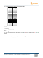
Download Helios FM 20/100 W User manual
Transcript
Helios FM 20/100 W User manual 87.5 – 108 MHz 20 OR 100 W STEREO AND MULTIPLEX COMPACT FM DIGITAL TRANSMITTER WITH TCP/IP MONITORING* *depending on options Date: 2011/12/05 ecreso WorldCast Systems Group web: www.ecreso.com - e-mail: [email protected] Helios FM 20/100 W, user manual– 12/2011 TABLE OF CONTENTS 1. INTRODUCTION ................................................................................................................................. 4 1.1. About Ecreso .............................................................................................................................. 4 1.2. Before you start .......................................................................................................................... 5 2. DESCRIPTION .................................................................................................................................... 6 2.1. General description .................................................................................................................... 6 2.2. Helios FM 20/100 W Description ................................................................................................ 7 2.2.1. Front panel ............................................................................................................................ 7 2.2.2. Rear panel ............................................................................................................................. 8 2.2.3. Opened cover ........................................................................................................................ 9 2.2.4. Synoptic............................................................................................................................... 10 2.2.5. 2U Rack............................................................................................................................... 11 3. TECHNICAL SPECIFICATIONS....................................................................................................... 12 3.1. RF section ................................................................................................................................ 12 3.2. Composite operation ................................................................................................................ 12 3.3. Stereo operation ....................................................................................................................... 12 3.4. Mono operation ........................................................................................................................ 12 3.5. AF inputs .................................................................................................................................. 13 3.6. HF output .................................................................................................................................. 13 3.7. Power supply ............................................................................................................................ 13 3.8. Interface panel .......................................................................................................................... 14 3.9. Environmental .......................................................................................................................... 14 3.10. Physical .................................................................................................................................... 14 3.11. Miscellaneous ........................................................................................................................... 14 4. STARTING UP YOUR TRANSMITTER ............................................................................................ 15 4.1. Connecting the transmitter ....................................................................................................... 15 4.2. Setting the transmitter .............................................................................................................. 16 4.3. Input selection .......................................................................................................................... 17 4.4. Setting the MPX inputs ............................................................................................................. 17 4.5. MPX configuration .................................................................................................................... 17 4.6. Setting the analog or AES inputs ............................................................................................. 17 4.7. Getting on air ............................................................................................................................ 17 5. FRONT SCREEN USE ...................................................................................................................... 18 5.1. Overview................................................................................................................................... 18 5.2. Working principe ....................................................................................................................... 18 5.3. Structure of the menus ............................................................................................................. 20 5.3.1. First level measurements .................................................................................................... 20 5.3.2. First level menus ................................................................................................................. 21 5.3.3. TX PARAMETERS Menu .................................................................................................... 22 5.3.4. ALARMS Menu.................................................................................................................... 22 5.3.5. INPUT SELECT Menu ........................................................................................................ 23 5.3.6. INPUT SWITCH Menu ........................................................................................................ 24 5.3.7. LINE1 Menu ........................................................................................................................ 25 5.3.8. MPX in Menu ....................................................................................................................... 26 5.3.9. Audio Gene Menu ............................................................................................................... 27 5.3.10. Modulation Menu ................................................................................................................. 28 5.3.11. Stereo encoder Menu .......................................................................................................... 29 5.3.12. RDS Menu ........................................................................................................................... 30 5.3.13. Network Menu ..................................................................................................................... 31 Page 2 Head Office : Parc d’activites Kennedy - 20, avenue Neil Armstrong – F-33700 Bordeaux-Merignac (France) Tel +33 (0)5 57 928 928 – Fax +33 (0)5 57 928 929 – www.ecreso.com – [email protected] Helios FM 20/100 W, user manual– 12/2011 5.3.14. COM Menu .......................................................................................................................... 32 5.3.15. Power supply Menu ............................................................................................................. 33 5.3.16. Temp/Fan Menu .................................................................................................................. 34 5.3.17. Time/Date Menu .................................................................................................................. 35 5.3.18. About Menu ......................................................................................................................... 36 5.3.19. Exit Menu ............................................................................................................................ 37 5.4. Parameters description ............................................................................................................ 38 5.4.1. INPUT SELECT Menu ........................................................................................................ 38 5.4.2. INPUT SWITCH Menu ........................................................................................................ 38 5.4.3. Menu LINE 1 (ANA) ............................................................................................................ 39 5.4.4. LINE 2 Menu (AES) ............................................................................................................. 40 5.4.5. MPX IN Menu ...................................................................................................................... 40 5.4.6. AUDIO GENE Menu ............................................................................................................ 41 5.4.7. MODULATION Menu .......................................................................................................... 42 5.4.8. STEREO ENCODER Menu ................................................................................................ 43 5.4.9. RDS Menu ........................................................................................................................... 44 6. SERIAL COMMANDS ....................................................................................................................... 48 6.1. Working principle ...................................................................................................................... 48 6.2. Serial commands.............................................................................. Erreur ! Signet non défini. 6.2.1. System commands ...................................................................... Erreur ! Signet non défini. 6.2.2. Measurement commands............................................................ Erreur ! Signet non défini. 6.2.3. Configuration commands ............................................................ Erreur ! Signet non défini. 6.2.4. Alarm commands ........................................................................ Erreur ! Signet non défini. 6.2.5. Input commands .......................................................................... Erreur ! Signet non défini. 6.2.6. Encoder commands .................................................................... Erreur ! Signet non défini. 6.2.7. RDS commands .......................................................................... Erreur ! Signet non défini. 6.2.8. Transmitter commands ............................................................... Erreur ! Signet non défini. 6.2.9. Status commands ....................................................................... Erreur ! Signet non défini. 6.2.10. Communication board commands .............................................. Erreur ! Signet non défini. 6.3. HyperTerminal connection ....................................................................................................... 49 7. REMOTE CONTROL AND MONITORING WITH THE GPIO BOARD ............................................ 60 7.1. Introduction ............................................................................................................................... 60 7.2. Description of control and monitoring functions ....................................................................... 60 7.3. Remote control function pinout ................................................................................................ 60 7.4. Remote monitoring function pinout .......................................................................................... 61 7.5. Physical representation of the GPIOs ...................................................................................... 62 7.6. Management using the optional TCP/IP board ........................................................................ 63 8. THE EMBEDDED WEBSITE ............................................................................................................ 65 8.1. Introduction ............................................................................................................................... 65 8.2. Connecting to the embedded web site ..................................................................................... 65 8.3. Viewing the Status.................................................................................................................... 66 ANNEXE A : .......................................................................................................................................... 79 FOR MORE INFORMATION ................................................................................................................. 80 Page 3 Head Office : Parc d’activites Kennedy - 20, avenue Neil Armstrong – F-33700 Bordeaux-Merignac (France) Tel +33 (0)5 57 928 928 – Fax +33 (0)5 57 928 929 – www.ecreso.com – [email protected] Helios FM 20/100 W, user manual– 12/2011 1. INTRODUCTION 1.1. About Ecreso Founded in 1956 near Bordeaux, ECRESO was created by radio broadcasting enthusiasts and counts today as one of the most important players on the international broadcasting stage. ECRESO offers analog and digital radio as well as digital TV transmitters (FM, DAB, DAB+, T-DMB, DVBT/H), low power transmitters, which are air-cooled, as well as high power devices either air or water-cooled. ECRESO is part of the WorldCast Systems group of companies which combines the collective expertise & extensive product portfolio of several major broadcast brands to offer turnkey systems in all major analog and digital technologies. Other brands within the group include: • Audemat who designs monitoring equipment for analog and digital radio and TV as well as an extensive range of facility remote control solutions. • APT Codecs who offer reliable and cost effective broadcast codec platforms delivering high quality content over IP, T1, E1, ISDN & Leased Lines. As such, WorldCast Systems can offer complete broadcast solutions for the delivery, transmission and monitoring of broadcast content throughout the broadcast chain. The group is founded on three core values: 1) Product innovation: Audemat places a key emphasis on Research & Development and its innovative approach has been repeatedly recognized by the industry. WorldCast Systems has won awards for innovation at consecutive NAB Shows for over 10 years. 2) Customer satisfaction: Audemat is dedicated to ensuring the best quality, value and service for its customers and has achieved IS0 9001 certification. 3) Sustainable Development: Audemat is committed to sustainable development and demonstrates this commitment in several ways: it has been ISO 14001 certified since 2007, adheres to the UN Global Compact project and all new products are developed in keeping with an eco-design philosophy and built within Audemat’s low energy consumption factory. Audemat/Ecreso employs around 80 employees at headquarters in Bordeaux-Merignac, France. Audemat/Ecreso also has a subsidiary in Miami, USA that manages the North & South American markets as well as sales offices in the UK, India and China. An extensive network of international dealers and distributors means that the company is represented in over 45 countries throughout Europe, Middle East, Africa and Asia. Page 4 Head Office : Parc d’activites Kennedy - 20, avenue Neil Armstrong – F-33700 Bordeaux-Merignac (France) Tel +33 (0)5 57 928 928 – Fax +33 (0)5 57 928 929 – www.ecreso.com – [email protected] Helios FM 20/100 W, user manual– 12/2011 1.2. Before you start This equipment complies with international mechanical and electrical standards. To maintain this compliance, as well as to ensure proper and safe working conditions and avoid electrical shocks and fire hazards, you must comply with the following recommendations: 1 - The device should only be utilized in the conditions described in the user manual. 2 - The device is designed for industrial usage and must only be operated by qualified personnel. 3 - The device may be heavy; it must be lifted and handled with care, specifically during unpacking and set up. Electrical precautions 4 - Unplug from mains outlet before any intervention. 5 - Any maintenance, adjustment or repair must be carried out by personnel specifically trained by WorldCast Systems. 6 - Before switching on the device, make sure the nominal voltage specified on the device matches the mains nominal voltage. 7 - The device should only be operated on a stable electrical network. If the electrical network is not stable, a power conditioner, such as a UPS, must be used 8 - The device must only be used with a plug that incorporates a protective ground contact. 9 - To avoid any risk of electrocution, the protection conductor must not be cut, intentionally or accidentally, either on the device or on the power cord. 10 - High quality shielded cables are mandatory. Environmental precautions 11 - It is necessary to verify that environmental conditions comply with those recommended in the manual. 12 - Nothing must obstruct the ventilation. 13 - To avoid any electromagnetic interference, the device must only be used when it is closed, installed in a cabinet and connected to the earth as per the instructions. 14 - The device should not be exposed to dripping or splashing and no objects filled with liquids, such as coffee cups, should be placed on the equipment. Precautions regarding the lithium battery This device includes a lithium battery. If the battery is not correctly replaced, there is a risk of explosion. Only replace it with a battery of the same type. Contact us before attempting to use another type 15 16 17 18 - Do not puncture the battery Do not throw the battery in fire Do not immerse the battery in water Do not throw away the used battery, recycle it instead. You may send it back to us if needed. If these precautions are not followed, the guarantee will be void. Page 5 Head Office : Parc d’activites Kennedy - 20, avenue Neil Armstrong – F-33700 Bordeaux-Merignac (France) Tel +33 (0)5 57 928 928 – Fax +33 (0)5 57 928 929 – www.ecreso.com – [email protected] Helios FM 20/100 W, user manual– 12/2011 2. DESCRIPTION 2.1. General description Combining the very latest technologies with our proven RF experience, our 20 W and 100 W exciters have been designed to offer an innovative and highly reliable solution. Among the first FM transmitters based on 6th Generation MOSFET, these transmitters are not only more robust, they also deliver efficiency of up to 74%. Top signal quality and performance are achieved thanks to the “FM Band Direct to Frequency” digital modulator which is at the heart of this range. The manufacturing quality and the simplicity of use make these truly powerful transmitters to broadcast analog FM programs. The Helios FM 20/100 W is fully protected against overheating, VSWR and lightning. In addition, several innovative features are available, such as RDS encoding and automated audio backup. Fully featured for local maintenance and configuration, it also allows full remote control by Web server, SNMP, RS232 or GPIOs*. * Options available with the current version are: • Basic RDS: the internal RDS encoder makes it possible to manage basic RDS parameters (PI, PS, TP, TA, PTY, MS, DI, radiotext, PTYN, group sequence, AF, 1 PSN, 2 DSN, dynamic scrolling PS) • GPIO: this additional board allows remote control and management of your transmitter. • TCP/IP: this additional board allows remote configuration via a web site and SNMP management Project co-financed by the European Union, involved in the Aquitaine Area, through the European Funds for local development. Page 6 Head Office : Parc d’activites Kennedy - 20, avenue Neil Armstrong – F-33700 Bordeaux-Merignac (France) Tel +33 (0)5 57 928 928 – Fax +33 (0)5 57 928 929 – www.ecreso.com – [email protected] Helios FM 20/100 W, user manual– 12/2011 2.2. Helios FM 20/100 W Description 2.2.1. Front panel LCD contrast RS232 port LCD display Navigation keys Indicators: CPU, Fault, Warning, RF (3 dB), VSWR and Interlock RF monitoring output RF on/off and local mode keys and LEDs Description of indicator LEDs: • CPU: blinks to indicate CPU activity • FAULT: major fault of the unit (RF / VSWR protection, Temperature, …) • WARNING: minor fault of the unit (ambient temperature, radiator temperature, fan, current, voltage, loss of signal). • VSWR: VSWR of the unit • RF (3dB) : 3 dB of the unit • INTERLOCK: indicates that internal or external safety links are not activated • RF: indicates that the unit is on RF=ON. Associated to the RF button • LOCAL: indicates that the unit is in local mode. Associated to the Local button Page 7 Head Office : Parc d’activites Kennedy - 20, avenue Neil Armstrong – F-33700 Bordeaux-Merignac (France) Tel +33 (0)5 57 928 928 – Fax +33 (0)5 57 928 929 – www.ecreso.com – [email protected] Helios FM 20/100 W, user manual– 12/2011 2.2.2. Rear panel N RF output Communication board (option) * Interlock MPX/SCA1 MPX/SCA2 19 kHz GPIO slot (option) Audio input Line1 (Ana or AES) Audio input Line2 (Ana or AES) Mains Ground * Two optional communication boards are available: TCP/IP board • 2 RS232 ports (COM1 and COM2) • 1 µSD card • 1 USB port • 1 Ethernet port • 1 CAN port CAN board • 2 RS232 ports (COM0 and COM1) • 1 slave USB port • 1 CAN port On the CAN board, the COM0 port is reserved for the unit’s upgrade. Please not that the 19 kHz output and the 10 MHz input are not enabled on this preliminary version. Page 8 Head Office : Parc d’activites Kennedy - 20, avenue Neil Armstrong – F-33700 Bordeaux-Merignac (France) Tel +33 (0)5 57 928 928 – Fax +33 (0)5 57 928 929 – www.ecreso.com – [email protected] Helios FM 20/100 W, user manual– 12/2011 2.2.3. Opened cover Audio inputs Optional communication board Optional GPIO board Mains filter RF amplifier bloc Surge protection (non present option) Digital modulator Low voltage power bloc High output power supply Page 9 Head Office : Parc d’activites Kennedy - 20, avenue Neil Armstrong – F-33700 Bordeaux-Merignac (France) Tel +33 (0)5 57 928 928 – Fax +33 (0)5 57 928 929 – www.ecreso.com – [email protected] Control board Helios FM 20/100 W, user manual– 12/2011 2.2.4. Synoptic Helios FM 20/100 W Audio L1 Audio 1 R1 AES1 L2 R2 Audio 2 Audio/IP AES2 Tuner MPX SCA Internal player 19 kHz output Page 10 Head Office : Parc d’activites Kennedy - 20, avenue Neil Armstrong – F-33700 Bordeaux-Merignac (France) Tel +33 (0)5 57 928 928 – Fax +33 (0)5 57 928 929 – www.ecreso.com – [email protected] Helios FM 20/100 W, user manual– 12/2011 2.2.5. 2U Rack The choice of stainless steel as material guarantees against corrosion. The rack structure and the structure of the monoblock front panel reinforce the device. The rectangular outline of the rounded front panel has a large LCD display protected by armored glass. This display can be read from a few yards away. The transport handles are mechanically interchangeable and can be removed with the front panel. The cover is fixed by a set of M3 POZIDRIV screws and can be easily removed. The user has access to every module to set the parameters of the device. Page 11 Head Office : Parc d’activites Kennedy - 20, avenue Neil Armstrong – F-33700 Bordeaux-Merignac (France) Tel +33 (0)5 57 928 928 – Fax +33 (0)5 57 928 929 – www.ecreso.com – [email protected] Helios FM 20/100 W, user manual– 12/2011 3. TECHNICAL SPECIFICATIONS 3.1. RF section Frequency range 87.5 to 108 MHz Summary of different steps 10 kHz Frequency stability < 10-6 per year Power range 0-20 W or 0-100 W @ ROS=1.35 Power output continuously 0-20 W or 0-100 W Spurious and harmonic suppression > 75 dBc 3.2. Composite operation Bandwidth > 20 Hz to 68 kHz @ 0.1 dB > 20 Hz to 92 kHz @ 0.4 dB Intermodulation distortion < 0.05% FM S/N ratio > 80 dB RMS @ 75 kHz deviation AM noise < 0.1% (50 dB) RMS (20-20 000 Hz) 3.3. Stereo operation Bandwidth > 20 Hz to 15 kHz @ 0.1 dB 38 kHz discontinuance > 50 dB Stereophonic separation > 50 dB Preemphasis 0 µs, 50 µs or 75 µs 3.4. Mono operation Bandwidth > 40 Hz to 15 kHz @ 0.1 dB Out of band rejection > 40 dB @ 19 kHz Preemphasis 0 µs, 50 µs or 75 µs Page 12 Head Office : Parc d’activites Kennedy - 20, avenue Neil Armstrong – F-33700 Bordeaux-Merignac (France) Tel +33 (0)5 57 928 928 – Fax +33 (0)5 57 928 929 – www.ecreso.com – [email protected] Helios FM 20/100 W, user manual– 12/2011 3.5. AF inputs Analog (LINE1) Connector "XLR" type Impedance > 10 kΩ by default, adjustable to 600 Ω by jumpers, unbalanced Bandwidth Software adjustable Level Software adjustable (-18/+18 dBu range) AES (LINE2) Connector "XLR" type Impedance > 110 Ω balanced Bandwidth Software adjustable Level Software adjustable (-20 to 0 dBFS range) Sampling rate Auto adjusted up to 192 kb/s Bit 16, 24, 32 Multiplex (MPX/SCA) Connector "BNC" type Impedance > 5 kΩ unbalanced Level Software adjustable (-18/+18 dBu range) 3.6. HF output Connector N type Impedance 50 Ω Monitoring (RF Monitor) Level 3.7. 10 dBm @ 20/100 W at main output Power supply Voltage 90 VAC to 264 VAC Frequency 50 Hz - 60 Hz Max consumption < 300 W @ nominal power Page 13 Head Office : Parc d’activites Kennedy - 20, avenue Neil Armstrong – F-33700 Bordeaux-Merignac (France) Tel +33 (0)5 57 928 928 – Fax +33 (0)5 57 928 929 – www.ecreso.com – [email protected] Helios FM 20/100 W, user manual– 12/2011 3.8. Interface panel Indicators Green LED: CPU activity Red LED: major fault Yellow LED: minor fault Red LED: RF fault (3 dB) Red LED: VSWR fault Green LED: safety interlock Screens Back lighted LCD: displays operating parameters and menus. Buttons +, -- and OK 3.9. Environmental Nominal operating temperature 5°C to 45°C Maximum operating temperature 0°C to 50°C Warehousing temperature -20°C to +70°C Warehousing time < 10 years Cooling Internal ventilation (2 x~1.6 l/s) 3.10. Physical Helios FM 20/100 W Overall dimension 19’’ (482.6 mm) X 2U (89 mm) X 470 mm Rack size without front panel 440.4 X 82 X 466.5 mm (WxHxD) Enclosure depth required 600 mm Mounting 19’’enclosure, with 4 M6X12 screws Weight around 6.5 kg 0 3.11. Miscellaneous Marking CE Standards 1999/5/CE (R&TTE) ETS 302 018 (EMC) ETS 300 384 (Radio) NF EN 60215 (Safety) Page 14 Head Office : Parc d’activites Kennedy - 20, avenue Neil Armstrong – F-33700 Bordeaux-Merignac (France) Tel +33 (0)5 57 928 928 – Fax +33 (0)5 57 928 929 – www.ecreso.com – [email protected] Helios FM 20/100 W, user manual– 12/2011 4. STARTING UP YOUR TRANSMITTER 4.1. Connecting the transmitter 2 3 5 1 5 4 1. 2. Make sure the safety loop is present on the rear panel. Connect the transmitter RF output to a 50 Ω load with a wattmeter. The 50 Ω charge power must be greater than 30 W for a 20 W transmitter and greater than 150 W for a 100 W transmitter. When you acquired your Helios FM 20/100 W, the RF amplifier is deactivated and power is set to 0 W. These settings can be adjusted using the PC application, the front panel application or serial commands. 3. Connect the audio or MPX inputs. 4. Connect a PC to the serial port on the front panel of the Helios. If your PC does not have a RS-232 port, use a USB/RS-232 cable. Connect to power using the provided cable; you may unscrew the cable loop and pass the power cable through it to secure it. Press the Local button on the front panel, then the RF button. Page 15 Head Office : Parc d’activites Kennedy - 20, avenue Neil Armstrong – F-33700 Bordeaux-Merignac (France) Tel +33 (0)5 57 928 928 – Fax +33 (0)5 57 928 929 – www.ecreso.com – [email protected] Helios FM 20/100 W, user manual– 12/2011 4.2. Setting the transmitter 1. On the PC, start the control software. This is a set-up tool that will allow you to quickly set and test your transmitter. All settings and measurements are also available on the front panel screen and with serial commands. 2. Select the port connected to the Helios and its speed. 3. The “Get all” button allows you to retrieve current values (9600, 8, N, 1 for the front panel connector). 4. Set the power (in W), the frequency (in MHz) and enable the RF. 5. Set other parameters as desired. Value formats for all parameters are available in the list of serial commands (see manual). 6. To send a parameter value to the transmitter, click the login button; no password is set in factory. Click then to the right of the text zone or click “Send all” to send all set values. 4.2.4 4.3 4.6 4.4 4.5 4.5 4.2.6 4.2.3 * Numbers above correspond to the paragraph numbers. Page 16 Head Office : Parc d’activites Kennedy - 20, avenue Neil Armstrong – F-33700 Bordeaux-Merignac (France) Tel +33 (0)5 57 928 928 – Fax +33 (0)5 57 928 929 – www.ecreso.com – [email protected] Helios FM 20/100 W, user manual– 12/2011 4.3. Input selection The input can be set to: • • • • 4.4. Line1 for the analog inputs (see sections 4.5 to 4.7) Line2 for the AES (see sections 4.5 to 4.7) MPX1 and MPX2 inputs (see sections 4.4 and 4.7) Internal generator Setting the MPX inputs • • • 4.5. Set the drive before processing between -6 and +6 dB Set the nominal level between -50 and +50 dBu Set the input type: o "MO" for mono o "ST" for stereo o "ST+R+S" for Stereo+RDS+SCA o "ST+R" for Stereo+RDS o "RDS" for RDS o "RDS+SCA" for RDS+SCA o "SCA" for SCA The corresponding filter will be applied. MPX configuration • Set the audio type to: o STEREO o MONO o MONO_L o MONO_R Selecting STEREO enables the internal 19 kHz; you will therefore want to select MONO for an MPX input. • • • • 4.6. Set the total deviation between 0 and 150 kHz Set the pilot deviation between 0 and 25.5 kHz If internal RDS is needed, set the RDS encoder deviation between 0 and 25.5 kHz (recommended deviation is 4 kHz) Set the max excursion between 0 and 200 kHz Setting the analog or AES inputs Use the LINE1 commands for the analog inputs. Use the LINE2 commands for the AES inputs. • • • 4.7. Set the drive before processing between -6 and +6 dB Set the nominal level between -50 and +50 dBu Set the pre-emphasis to 0, 50 or 75 µs depending on your country (50 µs in Europe, 75 µs in the USA). Getting on air 1. Disable the RF to turn off the transmitter using the front panel RF key. 2. Make sure the RF indicator LED is off. 3. Disconnect the load and connect the antenna to the transmitter RF output. 4. Enable the RF again using the front panel RF key. Page 17 Head Office : Parc d’activites Kennedy - 20, avenue Neil Armstrong – F-33700 Bordeaux-Merignac (France) Tel +33 (0)5 57 928 928 – Fax +33 (0)5 57 928 929 – www.ecreso.com – [email protected] Helios FM 20/100 W, user manual– 12/2011 5. FRONT SCREEN USE 5.1. Overview The transmitter can be entirely set using the front panel application. For audio configuration you will use the following menus: • Input Select: to select the main audio source and the secondary audio sources. • Input Switch: to set switching criteria between the main source and the secondary sources. • Line1 / Line2 / MPX1 / MPX2 / Audio Gene: to set levels and processes for each source. • Modulation: to set the deviation for each sub-carrier of the multiplex signal. In this menu you may also enable RDS and SCA. • Stereo Encoder: to choose the content of each sub-carrier of the multiplex signal (stereo, RDS, SCA). • RDS: to set the RDS. 5.2. Working principe ENTER Three keys allow you to browse through the menus: With the and keys, go from one screen to the next or rather from one command to the next: if 2 commands are available from a single screen, press twice to go to the next screen. A command is selected when an arrow is visible before its name. Example: 1 -> F R E Q 9 8 . 0 0 P F W D 7 5 0 The frequency is selected The and 1 F R E Q 9 8 . 0 0 P F W D -> 7 5 0 The power is selected keys are also used to adjust values after the edit mode has been enabled. To adjust a value, set each character at a time. Text values are set from left to right; number values are set from right to left. The ENTER button is used to: • Access a lower level menu • Enable the edit mode for parameters that can be modified • Confirm a new value • Return to the higher level menu. Page 18 Head Office : Parc d’activites Kennedy - 20, avenue Neil Armstrong – F-33700 Bordeaux-Merignac (France) Tel +33 (0)5 57 928 928 – Fax +33 (0)5 57 928 929 – www.ecreso.com – [email protected] Helios FM 20/100 W, user manual– 12/2011 Some menus include sub-menus. To make it easier to browse through the menus and locate the information, a small number is visible on the top left of the screen; it gives you the level of the menu you are viewing (1 or 2). If a text string is longer than the screen, press the ENTER key to access the text string and Page 19 Head Office : Parc d’activites Kennedy - 20, avenue Neil Armstrong – F-33700 Bordeaux-Merignac (France) Tel +33 (0)5 57 928 928 – Fax +33 (0)5 57 928 929 – www.ecreso.com – [email protected] to scroll. Helios FM 20/100 W, user manual– 12/2011 5.3. Structure of the menus 5.3.1. First level measurements These values are read-only; bargraphs may also be available. 9 8 . 0 0 M H z 1 0 0 W ||| ||| ||| ||| ||| ||| ||| ||| ||| ||| ||| ||| ||| P r = ||| ||| ||| ||| 8 W ENTER V S W R = 1 . 0 P E A K = 7 8 k H z ||| ||| ||| ||| ||| ||| ||| ||| ||| ||| ||| | See next page First level menus I N P U T S O U R C E L I N E 1 A N A 1 L E V E L ( d B U ) L = + 1 2 . 0 R = + 1 2 . 0 A E S 2 L E V E L ( d B F S ) L = + 1 2 . 3 R = + 1 2 . 1 M P X 1 L E V E L ( d B U ) 1 1 . 8 M P X 2 L E V E L ( d B U ) 1 2 . 1 P L A Y E R L E V E L 0 . 1 Page 20 Head Office : Parc d’activites Kennedy - 20, avenue Neil Armstrong – F-33700 Bordeaux-Merignac (France) Tel +33 (0)5 57 928 928 – Fax +33 (0)5 57 928 929 – www.ecreso.com – [email protected] Helios FM 20/100 W, user manual– 12/2011 5.3.2. First level menus ENTER 9 8 . 0 0 M H z 1 0 0 W ||| ||| ||| ||| ||| ||| ||| ||| ||| ||| ||| ||| ||| 9 8 . 0 0 M H z 1 0 0 W -> T X P A R A M E T E R S > 9 8 . 0 0 M H z 1 0 0 W -> R F P A R A M E T E R S > 9 8 . 0 0 M H z 1 0 0 W -> A L A R M S > 9 8 . 0 0 M H z 1 0 0 W -> I N P U T S E L E C T > 9 8 . 0 0 M H z 1 0 0 W -> I N P U T S W I T C H > 9 8 . 0 0 M H z -> L I N E 1 > 1 0 0 W 9 8 . 0 0 M H z -> L I N E 2 > 1 0 0 W 9 8 . 0 0 M H z 1 0 0 W -> M P X I N > The arrow > at the end of the 2nd line indicates there is a sub-menu. Press the “Enter” key to access it. 9 8 . 0 0 M H z 1 0 0 W -> A U D I O G E N E > Available menus vary depending on the options actually implemented on the transmitter, and its state. 9 8 . 0 0 M H z 1 0 0 W -> M O D U L A T I O N > Each menu is detailed in the following pages. 9 8 . 0 0 M H z -> R D S > 1 0 0 W 9 8 . 0 0 M H z 1 0 0 W -> S T E N C O D E R > 9 8 . 0 0 M H z -> G P I O > 1 0 0 W 9 8 . 0 0 M H z 1 0 0 W -> N E T W O R K > 9 8 . 0 0 M H z -> C O M > 1 0 0 W 9 8 . 0 0 M H z 1 0 0 W -> P O W E R S U P P L Y > 9 8 . 0 0 M H z 1 0 0 W -> T E M P / F A N > 9 8 . 0 0 M H z 1 0 0 W -> T I M E / D A T E > 9 8 . 0 0 M H z -> A B O U T > 1 0 0 W 9 8 . 0 0 M H z -> E X I T 1 0 0 W Page 21 Head Office : Parc d’activites Kennedy - 20, avenue Neil Armstrong – F-33700 Bordeaux-Merignac (France) Tel +33 (0)5 57 928 928 – Fax +33 (0)5 57 928 929 – www.ecreso.com – [email protected] Helios FM 20/100 W, user manual– 12/2011 5.3.3. TX PARAMETERS Menu 9 8 . 0 0 M H z 1 0 0 W -> T X P A R A M E T E R S > ENTER 1 -> F R E Q 9 8 . 0 0 P F W D 1 0 0 1 -> P W R 1 0 0 P F W D P R E F 1 0 0 5 2 1 3 D B -> 3 2 5 M A X V S W R 2 . 0 1 G O T O M A I N -> R F MAIN is selected * ENTER 9 8 . 0 0 M H z 1 0 0 W ||| ||| ||| ||| ||| ||| ||| ||| ||| ||| ||| ||| ||| RF is selected * * An arrow appears before the selected command Main measurement screen 5.3.4. ALARMS Menu 1 0 4 . 0 5 M H z 1 0 0 W -> A L A R M S > This read-only menu is only visible if alarms are present. It then displays one screen per current alarm: press the ENTER key then the key to scroll through them. Page 22 Head Office : Parc d’activites Kennedy - 20, avenue Neil Armstrong – F-33700 Bordeaux-Merignac (France) Tel +33 (0)5 57 928 928 – Fax +33 (0)5 57 928 929 – www.ecreso.com – [email protected] Helios FM 20/100 W, user manual– 12/2011 5.3.5. INPUT SELECT Menu 9 8 . 0 0 M H z 1 0 0 W -> I N P U T S E L E C T > ENTER 1 I N P U T S E L E C T -> M O D E : M A N U 1 I N P U T S E L E C T -> M A I N : L I N E 1 1 I N P U T -> B A C K U P S E L E C T 1 : L I N E 2 1 I N P U T -> B A C K U P S E L E C T 2 : M P X 1 1 I N P U T -> B A C K U P S E L E C T 3 : P L A Y E R 1 G O T O M A I N -> I N P U T MAIN is selected * ENTER 9 8 . 0 0 M H z 1 0 0 W ||| ||| ||| ||| ||| ||| ||| ||| ||| ||| ||| ||| ||| S E L INPUT-SEL is selected * * An arrow appears before the selected command Main measurement screen Page 23 Head Office : Parc d’activites Kennedy - 20, avenue Neil Armstrong – F-33700 Bordeaux-Merignac (France) Tel +33 (0)5 57 928 928 – Fax +33 (0)5 57 928 929 – www.ecreso.com – [email protected] 
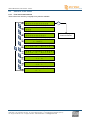
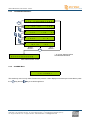
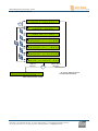
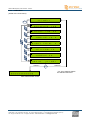
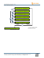
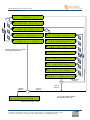
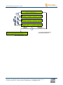
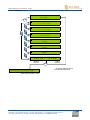
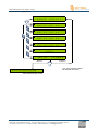
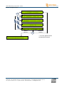
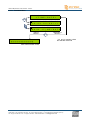
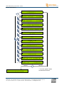
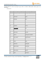
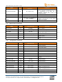
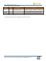
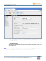
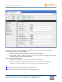
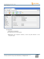
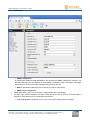
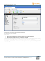
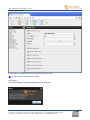
Helios FM 20/100 W, user manual– 12/2011 5.3.6. INPUT SWITCH Menu 9 8 , 0 0 M H z 1 0 0 W -> I N P U T S W I T C H > ENTER 1 I N P U T S W I T C H -> L I N E 1 > ENTER 1 I N P U T S W I T C H -> L I N E 2 > 2 S W I T C H -> L I N E 1 -> T H R E S H O L D : - 9 0 1 I N P U T S W I T C H -> M P X > 2 S W I T C H -> L I N E 1 -> S I L E N C E : B O T H 1 I N P U T S W I T C H -> P L A Y E R > 2 S W I T C H -> L I N E 1 -> D E L A Y : 1 2 0 1 I N P U T S W I T C H -> A U D I O / I P > 2 S W I T C H -> L I N E 1 -> B A C K D E L A Y : 3 0 1 I N P U T S W I T C H -> T U N E R > 2 G O -> S W I T C H 1 I N P U T S W I T C H -> C R O S S F A D E : 1 8 . 5 1 -> M A I N G O T O -> I N P U T - S W MAIN is selected * ENTER T O -> L I N E 1 ENTER LINE1 is selected * SWITCH is selected * INPUT-SW is selected * 9 8 . 0 0 M H z 1 0 0 W ||| ||| ||| ||| ||| ||| ||| ||| ||| ||| ||| ||| ||| * An arrow appears before the selected command Page 24 Head Office : Parc d’activites Kennedy - 20, avenue Neil Armstrong – F-33700 Bordeaux-Merignac (France) Tel +33 (0)5 57 928 928 – Fax +33 (0)5 57 928 929 – www.ecreso.com – [email protected] Helios FM 20/100 W, user manual– 12/2011 5.3.7. LINE1 Menu (similar to the Line2 menu) 9 8 . 0 0 M H z -> L I N E 1 > 1 0 0 W ENTER 1 L I N E 1 P R E S E N C E : L & R 1 L I N E 1 -> L E V E L : + 0 6 . 0 0 1 L I N E 1 -> D R I V E : + 0 . 0 1 L I N E 1 -> R I G H T T R I M : 1 L I N E 1 -> F I L T E R : 1 5 1 L I N E 1 -> P R E A C : 5 0 1 G O -> M A I N MAIN is selected * 9 8 . 0 0 M H z 1 0 0 W ||| ||| ||| ||| ||| ||| ||| ||| ||| ||| ||| ||| ||| 0 . 0 T O -> L I N E 1 ENTER LINE1 is selected * * An arrow appears before the selected command Main measurement screen Page 25 Head Office : Parc d’activites Kennedy - 20, avenue Neil Armstrong – F-33700 Bordeaux-Merignac (France) Tel +33 (0)5 57 928 928 – Fax +33 (0)5 57 928 929 – www.ecreso.com – [email protected] Helios FM 20/100 W, user manual– 12/2011 5.3.8. MPX in Menu 9 8 . 0 0 M H z 7 5 0 W -> M P X I N > ENTER 1 1 M P X I N -> M P X 1 > ENTER M P X I N -> M P X 2 > 1 G O -> M A I N T O M P X - I N The MPX2 menu is similar to the MPX1 menu 2 M P X - I N -> M P X 1 -> T Y P E : S T + R + S 2 M P X - I N -> M P X 1 P R E S E N C E : S T + R + S 2 M P X - I N -> M P X 1 -> L E V E L : + 0 6 . 0 0 2 M P X - I N -> M P X 1 -> D R I V E : + 0 . 0 2 M P X - I N -> M P X 1 R M S : - 1 2 6 2 M P X - I N -> M P X 1 P E A K : - 1 1 8 2 G O -> M P X - I N T O M P X 1 ENTER MAIN is selected * ENTER MPX-IN is selected * 9 8 . 0 0 M H z 1 0 0 W ||| ||| ||| ||| ||| ||| ||| ||| ||| ||| ||| ||| ||| MPX1 is selected * MPX-IN is selected * * An arrow appears before the selected command Main measurement screen Page 26 Head Office : Parc d’activites Kennedy - 20, avenue Neil Armstrong – F-33700 Bordeaux-Merignac (France) Tel +33 (0)5 57 928 928 – Fax +33 (0)5 57 928 929 – www.ecreso.com – [email protected] Helios FM 20/100 W, user manual– 12/2011 5.3.9. Audio Gene Menu 9 8 . 0 0 M H z 1 0 0 W -> A U D I O G E N E > ENTER 1 A U D I O G E N E -> S T A T E : O F F 1 A U D I O G E N E -> P R E A C : 5 0 1 A U D I O G E N E -> L E V E L : + 0 6 . 0 0 1 A U D I O G E N E -> F R E Q : 1 0 0 0 0 0 . 0 0 1 -> M A I N MAIN is selected * 9 8 . 0 0 M H z 1 0 0 W ||| ||| ||| ||| ||| ||| ||| ||| ||| ||| ||| ||| ||| G O T O A U D I O - G E N E ENTER AUDIO-GENE is selected * * An arrow appears before the selected command Main measurement screen Page 27 Head Office : Parc d’activites Kennedy - 20, avenue Neil Armstrong – F-33700 Bordeaux-Merignac (France) Tel +33 (0)5 57 928 928 – Fax +33 (0)5 57 928 929 – www.ecreso.com – [email protected] Helios FM 20/100 W, user manual– 12/2011 5.3.10. Modulation Menu 9 8 . 0 0 M H z 7 5 0 W -> M O D U L A T I O N > ENTER 1 M O D U L A T I O N R M S : - 1 2 6 1 M O D U L A T I O N -> D E V M P X : 7 5 . 0 1 M O D U L A T I O N -> D E V A U D I O : 6 3 . 9 1 M O D U L A T I O N -> D E V P I L O T : 7 . 1 1 M O D U L A T I O N -> D E V R D S : 4 . 0 1 M O D U L A T I O N -> P H I R D S : + 9 0 . 0 0 1 M O D U L A T I O N -> R D S S T A T E : O N 1 M O D U L A T I O N -> D E V S C A : 0 . 0 1 M O D U L A T I O N -> S C A S T A T E : O F F 1 M O D U L A T I O N C L I P : 8 5 1 -> M A I N MAIN is selected * 9 8 . 0 0 M H z 1 0 0 W ||| ||| ||| ||| ||| ||| ||| ||| ||| ||| ||| ||| ||| G O T O M O D U L A T I O N ENTER MODULATION is selected * * An arrow appears before the selected command Main measurement screen Page 28 Head Office : Parc d’activites Kennedy - 20, avenue Neil Armstrong – F-33700 Bordeaux-Merignac (France) Tel +33 (0)5 57 928 928 – Fax +33 (0)5 57 928 929 – www.ecreso.com – [email protected] Helios FM 20/100 W, user manual– 12/2011 5.3.11. Stereo encoder Menu 9 8 . 0 0 M H z 7 5 0 W -> S T E N C O D E R > ENTER 1 S T E N C O D E R -> M O / S T : S T E R E O 1 S T A U D I O 1 S T E N C O D E R -> R D S O P : M A N U 1 S T E N C O D E R -> R D S I N : M P X 1 1 S T E N C O D E R -> S C A I N : M P X 2 E N C O D E R C H : L I N E 2 1 S T E N C O D E R -> 1 9 k O U T L E V E L : 1 G O -> M A I N MAIN is selected * 9 8 . 0 0 M H z 1 0 0 W ||| ||| ||| ||| ||| ||| ||| ||| ||| ||| ||| ||| ||| T O -> C O D E R ENTER CODER is selected * * An arrow appears before the selected command Main measurement screen Page 29 Head Office : Parc d’activites Kennedy - 20, avenue Neil Armstrong – F-33700 Bordeaux-Merignac (France) Tel +33 (0)5 57 928 928 – Fax +33 (0)5 57 928 929 – www.ecreso.com – [email protected] Helios FM 20/100 W, user manual– 12/2011 5.3.12. RDS Menu 9 8 . 0 0 M H z -> R D S > ENTER 1 0 0 W 1 R D S C U R R E N T : M A I N ( 1 ) 1 R D S -> M A I N - D S N ( 1 ) > ENTER 1 R D S -> A L T - D S N ( 2 ) > 2 R D S -> M A I N - D S N -> P I : F 1 0 B -> P T Y : 1 9 1 G O -> M A I N 2 R D S -> M A I N - D S N -> P S : M Y R A D I O 2 R D S -> M A I N - D S N -> M S : 0 9 -> D I : 1 2 2 R D S -> M A I N - D S N -> T A / T P : T A T P T O -> R D S The ALT-DSN menu is similar to the MAIN-DSN menu 2 R D S -> M A I N - D S N -> A F : 8 8 . 5 ; 1 0 8 . 0 ; 9 2 R D S -> M A I N - D S N -> R T : R A D I O T E X T 2 R D S -> M A I N - D S N -> G S : 0 A ; 1 A ; E N D 1 -> R D S G O T O -> M A I N - D S N ENTER MAIN is selected * ENTER RDS is selected * 9 8 . 0 0 M H z 1 0 0 W ||| ||| ||| ||| ||| ||| ||| ||| ||| ||| ||| ||| ||| MAIN-DSN is selected * RDS is selected * * An arrow appears before the selected command Main measurement screen Page 30 Head Office : Parc d’activites Kennedy - 20, avenue Neil Armstrong – F-33700 Bordeaux-Merignac (France) Tel +33 (0)5 57 928 928 – Fax +33 (0)5 57 928 929 – www.ecreso.com – [email protected] Helios FM 20/100 W, user manual– 12/2011 5.3.13. Network Menu 9 8 . 0 0 M H z 1 0 0 W -> N E T W O R K > ENTER 1 N E T W O R K -> A D R -> 1 9 2 . 1 6 8 . 0 1 2 . 1 0 3 1 N E T W O R K -> M A S K -> 2 5 5 . 2 5 5 . 2 5 5 . 0 0 0 1 G O -> M A I N MAIN is selected * 9 8 . 0 0 M H z 1 0 0 W ||| ||| ||| ||| ||| ||| ||| ||| ||| ||| ||| ||| ||| T O -> N E T W O R K ENTER NETWORK is selected * * An arrow appears before the selected command Main measurement screen Page 31 Head Office : Parc d’activites Kennedy - 20, avenue Neil Armstrong – F-33700 Bordeaux-Merignac (France) Tel +33 (0)5 57 928 928 – Fax +33 (0)5 57 928 929 – www.ecreso.com – [email protected] Helios FM 20/100 W, user manual– 12/2011 5.3.14. COM Menu 9 8 . 0 0 M H z -> C O M > 1 0 0 W ENTER 1 L O C A L C O M S P E E D -> 1 1 5 2 0 0 1 C O M 1 S P E E D -> 1 1 5 2 0 0 1 C O M 2 S P E E D -> 1 1 5 2 0 0 1 L O C A L C O M -> O N E C H O 1 C O M 1 E C H O -> O N 1 C O M 2 E C H O -> O N 1 G O -> M A I N MAIN is selected * 9 8 . 0 0 M H z 1 0 0 W ||| ||| ||| ||| ||| ||| ||| ||| ||| ||| ||| ||| ||| T O -> C O M ENTER COM is selected * * An arrow appears before the selected command Main measurement screen Page 32 Head Office : Parc d’activites Kennedy - 20, avenue Neil Armstrong – F-33700 Bordeaux-Merignac (France) Tel +33 (0)5 57 928 928 – Fax +33 (0)5 57 928 929 – www.ecreso.com – [email protected] Helios FM 20/100 W, user manual– 12/2011 5.3.15. Power supply Menu 9 8 . 0 0 M H z 1 0 0 W -> P O W E R S U P P L Y > ENTER 1 C U R 1 : 2 1 . 2 A V O L T 1 : 4 8 . 2 V 1 C U R 2 : 2 1 . 2 A V O L T 2 : 4 8 . 2 V 1 C U R 3 : 2 1 . 2 A V O L T 3 : 4 8 . 2 V 1 C U R 4 : 2 1 . 2 A V O L T 4 : 4 8 . 2 V 1 1 S T A N D B Y -> O F F G O -> M A I N MAIN is selected * 9 8 . 0 0 M H z 1 0 0 W ||| ||| ||| ||| ||| ||| ||| ||| ||| ||| ||| ||| ||| T O -> P O W E R ENTER POWER is selected * * An arrow appears before the selected command Main measurement screen Page 33 Head Office : Parc d’activites Kennedy - 20, avenue Neil Armstrong – F-33700 Bordeaux-Merignac (France) Tel +33 (0)5 57 928 928 – Fax +33 (0)5 57 928 929 – www.ecreso.com – [email protected] Helios FM 20/100 W, user manual– 12/2011 5.3.16. Temp/Fan Menu 9 8 . 0 0 M H z 7 5 0 W -> T E M P / F A N > ENTER 1 T ° A M B : 3 1 ° C T ° H E A T : 5 2 ° C 1 F A N 1 : 2 0 0 0 r p m F A N 2 : 2 0 0 0 r p m 1 M A X A M B -> 5 0 ° C 1 -> M A I N MAIN is selected * 9 8 . 0 0 M H z 1 0 0 W ||| ||| ||| ||| ||| ||| ||| ||| ||| ||| ||| ||| ||| G O T O -> T E M P / F A N ENTER TEMP/FAN is selected * * An arrow appears before the selected command Main measurement screen Page 34 Head Office : Parc d’activites Kennedy - 20, avenue Neil Armstrong – F-33700 Bordeaux-Merignac (France) Tel +33 (0)5 57 928 928 – Fax +33 (0)5 57 928 929 – www.ecreso.com – [email protected] Helios FM 20/100 W, user manual– 12/2011 5.3.17. Time/Date Menu 9 8 . 0 0 M H z 1 0 0 W -> T I M E / D A T E > ENTER 1 H H M M 1 4 : 0 4 1 -> M A I N MAIN is selected * 9 8 . 0 0 M H z 1 0 0 W ||| ||| ||| ||| ||| ||| ||| ||| ||| ||| ||| ||| ||| D D M M Y Y 2 3 / 0 6 / 1 1 G O T O -> T I M E / D A T E ENTER TIME/DATE is selected * * An arrow appears before the selected command Main measurement screen Page 35 Head Office : Parc d’activites Kennedy - 20, avenue Neil Armstrong – F-33700 Bordeaux-Merignac (France) Tel +33 (0)5 57 928 928 – Fax +33 (0)5 57 928 929 – www.ecreso.com – [email protected] Helios FM 20/100 W, user manual– 12/2011 5.3.18. About Menu 1 0 4 . 0 5 M H z -> A B O U T > 7 5 0 W ENTER 1 S Y S T Y P E : H 1 0 S Y S P C A P : 7 5 0 W 1 T X 1 T X T Y P E : H 1 0 P C A P : 7 5 0 W T X -> T X N A M E G L T 7 5 1 S O F T R E L L I S T -> C P U : 0 1 0 0 ; E X C : 0 1 1 S O F T R E L E A S E 0 1 0 0 1 H A R D R E L 0 3 1 C A N I D -> 1 2 1 D A T E C A L I B 2 3 0 6 2 0 1 1 1 S E R I A L N U M B E R 0 1 2 5 A A 1 1 1 U P T I M E 1 0 2 8 5 H 1 O P T I O N S L I S T -> G P I O , I P , A U D I O 1 G O -> M A I N MAIN is selected * 9 8 . 0 0 M H z 1 0 0 W ||| ||| ||| ||| ||| ||| ||| ||| ||| ||| ||| ||| ||| T O -> A B O U T ENTER ABOUT is selected * * An arrow appears before the selected command Main measurement screen Page 36 Head Office : Parc d’activites Kennedy - 20, avenue Neil Armstrong – F-33700 Bordeaux-Merignac (France) Tel +33 (0)5 57 928 928 – Fax +33 (0)5 57 928 929 – www.ecreso.com – [email protected] Helios FM 20/100 W, user manual– 12/2011 5.3.19. Exit Menu 9 8 . 0 0 M H z -> E X I T 1 0 0 W ENTER 9 8 . 0 0 M H z 1 0 0 W ||| ||| ||| ||| ||| ||| ||| ||| ||| ||| ||| ||| ||| Main measurement screen Page 37 Head Office : Parc d’activites Kennedy - 20, avenue Neil Armstrong – F-33700 Bordeaux-Merignac (France) Tel +33 (0)5 57 928 928 – Fax +33 (0)5 57 928 929 – www.ecreso.com – [email protected] Helios FM 20/100 W, user manual– 12/2011 5.4. Main parameters description Parameters are described for the main menus; serial commands are indicated in parenthesis. Possible values and/or value format are indicated for each parameter. 5.4.1. INPUT SELECT Menu These parameters are available as INPUT serial commands (see section 6.2.5), but are managed differently: the PRIO parameter for each input sets the selection order for the various audio sources. MODE With this parameter, choose whether audio source selection is done manually or automatically. In manual mode, the user selected audio source is used regardless of the state of the audio source. In auto mode, the effective audio source depends directly on the switching configuration (set in the Input Switch menu) and on the channels selected as Main or as Backup (1, 2 or 3). MANU or AUTO MAIN With this parameter, select the main audio source. LINE1, LINE2, MPX1, MPX2 or GENE BACKUP 1 / BACKUP 2 / BACKUP 3 With this parameters, select the audio sources which the transmitter will switch to in case of issue. LINE1, LINE2, MPX1, MPX2 ou GENE 5.4.2. INPUT SWITCH Menu This parameter is available as a CONF serial command (see section 6.2.3) CROSSFADE (CONF.CROSSFADE) - – read/write With this parameter, set the crossfade time between channels when switching from one to the next (in seconds). From 0 to 25.5 s LINE 1 or 2 / MPX / PLAYER sub menu These parameters are available as INPUT.LINE1.SW / INPUT.LINE2.SW / INPUT.MPX.SW / INPUT.PLAYER.SW serial commands (see section 6.2.5). THRESHOLD (INPUT.xx.SW.THRESH) – read/write With this parameter, set the silence threshold level in dBFS on the selected channel. From -90 to 0 dBFS SILENCE (INPUT.xx.SW.SILENCE) – read/write With this parameter, select the channel (L / R / L or R / L and R) on which silence detection must be performed. L, R, ANY or BOTH Page 38 Head Office : Parc d’activites Kennedy - 20, avenue Neil Armstrong – F-33700 Bordeaux-Merignac (France) Tel +33 (0)5 57 928 928 – Fax +33 (0)5 57 928 929 – www.ecreso.com – [email protected] Helios FM 20/100 W, user manual– 12/2011 DELAY (INPUT.xx.SW.DELAY) – read/write With this parameters, set the switching delay in seconds when audio loss occurs. From 1 to 120 s BACK DELAY (INPUT.xx.SW.BACKDELAY) – read/write With this parameters, set the delay before returning to the highest priority channel, in seconds. From 0 to 30 s 5.4.3. Menu LINE 1 (ANA) These parameters are available as INPUT.LINE1 serial commands (see section 6.2.5). PRESENCE (INPUT.LINE1.PRESENCE) – read only This parameter indicates the presence of audio signal at the input: none, left, right or L&R. NONE, L, R, L&R LEVEL (INPUT.LINE1.LEVEL) – read/write This parameter is the max audio peak in dBu that can come from the transmitter on the LINE1 input. For example, if the audio peak from the source is +6 dBu, this parameter must be set to +6 dBu for optimal operation. If you do not know the audio source level, you may use an audio analyzer or display first level measurements on the front panel to read the LINE1 LEVEL. Be aware that if the level is poorly set the deviation may become too low or too high. This level is also called nominal level, i.e. the level producing the deviation as set in the Modulation menu. From -18 dBu to +18 dBu DRIVE (INPUT.LINE1.DRIVE) – read/write With this parameter, you can slightly compensate the input audio level. It directly affects the final deviation. A negative value decreases the deviation; a positive value can increase the deviation and/or cause the MPX hard clipper to be used (if enabled) which in turn may lead to audio distortion. We recommend you leave it at 0 dB. From -6 dB to +6 dB RIGHT TRIM (INPUT.LINE1.TRIM) – read/write With this parameter, you can correct the balance between the Left and Right channels. However, it is better to look for and correct the cause of a lack of balance (before the transmitter) rather than correcting it at this stage. A positive value increases the Right channel; a negative value decreases the Right channel level. It is best to leave it at 0 dB. From -3 dB to +3 dB FILTER (INPUT.LINE1.FLT) – read/write This parameter is crucial: it set the low-pass filter applied on the audio input. The FM bandwidth is limited to 15 kHz, so the filter must be set to 15 kHz for the FM. Digital technology and the quality of the internal stereo encoder make it possible to set the filter at 16 or 17 kHz while maintaining an acceptable pilot Page 39 Head Office : Parc d’activites Kennedy - 20, avenue Neil Armstrong – F-33700 Bordeaux-Merignac (France) Tel +33 (0)5 57 928 928 – Fax +33 (0)5 57 928 929 – www.ecreso.com – [email protected] Helios FM 20/100 W, user manual– 12/2011 protection. Select 0 kHz to disable the filter: this solution can be used in mono operation (in stereo operation, the incidence on the MPX signal and its sub-carrier would be too great) or when a 15 kHz filter is already used upstream as with an FM processor for instance. In this specific situation, you may also use 2 filters, the standard 15 kHz standard filter with the external processor, plus the 16 kHz transmitter filter. The listeners will hear the processor’s filter; the internal filter will take the relay in case of issue with the processor. 0, 15, 16 or 17 kHz PREACC (INPUT.LINE1.PREAC) – read/write With this parameter, set the pre-emphasis. Select 0 µs is the audio signal is pre-emphasized before getting to the transmitter. Otherwise, select according to the country: 50 µs in Europe, 75 µs in the USA. 0, 50 or 75 µs 5.4.4. LINE 2 Menu (AES) These parameters are available as INPUT.LINE2 serial commands (see section 6.2.5). They are identical to LINE1 menu parameters, except for the level. LEVEL (INPUT.LINE2.LEVEL) – read/write This parameter is the max audio peak in dBu that can come from the transmitter on the LINE2 input. For example, if the audio peak from the source is -4 dBFS, this parameter must be set to -4 dBFS for optimal operation. If you do not know the audio source level, you may use an audio analyzer or display first level measurements on the front panel to read the LINE2 LEVEL. Be aware that if the level is poorly set the deviation may become too low or too high. This level is also called nominal level, i.e. the level producing the deviation as set in the Modulation menu. From -20 dBFS to 0 dBFS 5.4.5. MPX IN Menu MPX1 or MPX2 Sub-menu These parameters are available as INPUT.MPX1 / INPUT.MPX2 serial commands (see section 6.2.5). TYPE (INPUT.MPXn.TYPE) – read/write This parameter applies a filter to extract the type of signal needed on the MPXn input. This filtered signal will become the MPXn channel audio signal. Note that when switching from stereo to mono, the total deviation is maintained. MO (mono), ST (stereo), ST+R+S (stereo+RDS+SCA), ST+R (stereo+RDS), RDS, R+S (RDS+SCA), SCA or NONE PRESENCE (INPUT.MPXn.PRESENCE) – read only Indique la composition du signal sur l’entrée MPXn. MO (mono), MO+R (mono+RDS), MO+R+S (mono+RDS+SCA), ST (stereo), ST+R (stereo+RDS) ou ST+R+S (stereo+RDS+SCA) LEVEL (INPUT.MPXn.LEVEL) – read/write This parameter is the max audio peak in dBu that can come from the transmitter on the MPX input. For example, if the audio peak from the source is +6 dBu, this parameter must be set to +6 dBu for optimal operation. If you do not know the audio source level, you may use an audio analyzer or display first level Page 40 Head Office : Parc d’activites Kennedy - 20, avenue Neil Armstrong – F-33700 Bordeaux-Merignac (France) Tel +33 (0)5 57 928 928 – Fax +33 (0)5 57 928 929 – www.ecreso.com – [email protected] Helios FM 20/100 W, user manual– 12/2011 measurements on the front panel to read the MPXn LEVEL. Be aware that if the level is poorly set the deviation may become too low or too high. This level is also called nominal level, i.e. the level producing the deviation as set in the Modulation menu. From -18 dBu to +18 dBu DRIVE (INPUT.MPXn.DRIVE) – read/write With this parameter, you can slightly compensate the input audio level. It directly affects the final deviation. A negative value decreases the deviation; a positive value can increase the deviation and/or cause the MPX hard clipper to be used (if enabled) which in turn may lead to audio distortion. We recommend you leave it at 0 dB. From -6 dB to +6 dB RMS (INPUT.MPXn.RMS) – read only This parameter indicates the average value of the transmitted signal’s excursion in kHz. From -150 to +150 kHz PEAK (INPUT.MPXn.PEAK) – read only This parameter indicates the peak value of the transmitted signal’s excursion in kHz. From -150 to +150 kHz 5.4.6. AUDIO GENE Menu The audio generator is a multiplex channel and is therefore not affected by the stereo encoder parameters. These parameters are available as INPUT.AUDIOGEN serial commands (see section 6.2.5). STATE (INPUT.AUDIOGEN.STATE) – read/write With this parameter, set the type of MPX signal generated by the internal generator. OFF, PILOT, L, R, L+R (mono) or L-R (stereo) PREAC (INPUT.AUDIOGEN.PREAC) – read/write With this parameter, set the pre-emphasis. Select 0 µs is the audio signal is pre-emphasized before getting to the transmitter. Otherwise, select according to the country: 50 µs in Europe, 75 µs in the USA. 0, 50 or 75 µs LEVEL (INPUT.AUDIOGEN.LEVEL) – read/write With this parameter, set the internal generator audio level. From -100.00 to 12.00 dBFS FREQ (INPUT.AUDIOGEN.FREQ) – read/write With this parameter, set the internal generator audio frequency. From 0 to 100000.00 Hz Page 41 Head Office : Parc d’activites Kennedy - 20, avenue Neil Armstrong – F-33700 Bordeaux-Merignac (France) Tel +33 (0)5 57 928 928 – Fax +33 (0)5 57 928 929 – www.ecreso.com – [email protected] Helios FM 20/100 W, user manual– 12/2011 5.4.7. MODULATION Menu These parameters are available as MEAS.DEV and CONF serial commands (see section 6.2.2 and 6.2.3). RMS (MEAS.DEV.RMS) – read only This parameter indicates the average value of the transmitted signal’s excursion in kHz. From -150 to +150 kHz DEV MPX (CONF.DEV.MPX) – read/write With this parameter, set the maximum MPX deviation in kHz generated when the audio source is at the nominal level (the nominal level is set with the LEVEL parameter of the menus: LINE1, LINE2, MPX1 or MPX2). It is often set at 75 kHz but this value may vary according to the country and relevant regulatory authorities. To ensure the sub-carrier levels remain stable, this parameter directly changes the audio deviation. From 0 to 150.00 kHz DEV AUDIO (CONF.DEV.AUDIO) – read/write With this parameter, set the maximum audio deviation in kHz generated when the audio source is at the nominal level (the nominal level is set with the LEVEL parameter of the menus: LINE1, LINE2, MPX1 or MPX2). The audio deviation is set automatically when the MPX deviation parameter is set; however, it is possible to set the audio deviation rather than the MPX deviation. Increasing or decreasing the audio deviation affects the total deviation and thus automatically adjusts the MPX deviation. Make sure to avoid overmodulation. From 0 to 150.00 kHz DEV PILOT (CONF.DEV.PILOT) – read/write With this parameter, set the 19 kHz pilot deviation. For countries modulating at 75 kHz, the pilot deviation should be 10% of the total deviation, i.e. 7.5 kHz without RDS or 7.1 kHz if RDS is used. From 0 to 25.5 kHz DEV RDS (CONF.DEV.RDS) – read/write With this parameter, set the RDS sub-carrier deviation. The most widely used value is 4 kHz. From 0 to 25.5 kHz PHI RDS (CONF.PHASE.RDS) – read/write With this parameter, set the RDS sub-carrier phase in relation to the pilot sub-carrier. We recommend setting it at 90°. From -180 à to180° RDS STATE (CONF. STATE.RDS) – read/write With this parameter, enable or disable the RDS. When the RDS is enabled or disabled, the RDS deviation is automatically subtracted from or added to the audio deviation to maintain the same total deviation. Off/On DEV SCA (CONF.DEV.SCA) – read/write With this parameter, set the SCA deviation (auxiliary sub-carrier other than RDS), as needed. From 0 to 25.5 kHz Page 42 Head Office : Parc d’activites Kennedy - 20, avenue Neil Armstrong – F-33700 Bordeaux-Merignac (France) Tel +33 (0)5 57 928 928 – Fax +33 (0)5 57 928 929 – www.ecreso.com – [email protected] Helios FM 20/100 W, user manual– 12/2011 SCA STATE (CONF. STATE.SCA) – read/write With this parameter, enable or disable the SCA. When the SCA is enabled or disabled, the SCA deviation is automatically subtracted from or added to the audio deviation to maintain the same total deviation. Off/On CLIP (CONF. DEV.CLIP) – read/write With this parameter, set the MPX hard clipper to prevent any possibility of overmodulation on the modulator itself. This process is carried out digitally right before the RF generation, and is therefore enabled on all the inputs. If the deviation is greater than the configured value (in kHz), the MPX hard clipper is automatically enabled. Unlike FM limiters/clippers used in audio processing, this clipper cannot be used continuously for it generates a noticeable audio distortion. It is therefore best to set it at 0, or at the maximum authorized deviation, plus a few kHz to ensure additional security with the audio processor. From 0 to 200 5.4.8. STEREO ENCODER Menu These parameters are available as CODER serial commands (see section 6.2.6). MO/ST (CODER.MOST) – read/write With this parameter, set the stereo generator in mono or stereo mode. For mono, there are 3 options: Left channel broadcast in mono (Mono_L), right channel broadcast in mono (Mono_R), the sum Left+Right broadcast in mono (Mono). Otherwise left and right channels are broadcasted in stereo. STEREO, MONO, MONO_L or MONO_R AUDIO CH (CODER.SELECT.AUDIO) – read only This parameter indicates the channel used by the modulator for the audio, as set with the INPUT.SELECT menu. NONE, AUTO, LINE1, LINE2, MPX1, MPX2 or GENE RDS CH (CODER.CURRENT.RDS) – read only This parameter indicates the channel used by the modulator for the RDS, as set with the RDS IN parameter. NONE, MPX1, MPX2 or INTERNAL RDS OP (CODER.RDS.OPERATION) – read/write With this parameter, on loss of RDS in the MPX, add RDS either automatically or manually. Auto or Manu RDS IN (CODER.SELECT.RDS) – read/write With this parameter, set the RDS component source of the broadcast signal either with an external source or with the internal encoder. MPX1, MPX2 or INTERNAL SCA IN (CODER.SELECT.SCA) – read/write With this parameter, set the SCA component source of the broadcast signal MPX1 or MPX2 Page 43 Head Office : Parc d’activites Kennedy - 20, avenue Neil Armstrong – F-33700 Bordeaux-Merignac (France) Tel +33 (0)5 57 928 928 – Fax +33 (0)5 57 928 929 – www.ecreso.com – [email protected] Helios FM 20/100 W, user manual– 12/2011 19k OUT LEVEL (CODER.19KOUT.LEVEL) – read/write With this parameter, enable/disable the rear panel 19 kHz clock and set its output level. 0=off; between 1 and 7: set a level between 0.9 and 1.1 V peak-to-peak. 5 corresponds to 1 V. From 0 to 8 5.4.9. RDS Menu With the Basic RDS option, configure up to 2 DSNs each with a main PSN. Among other things, the DSNs allow fast and easy changing of the encoder settings remotely. Note: the RDS is enabled in the STEREO ENCODER menu. These parameters are available as RDS serial commands (see section 6.2.7). CURRENT MAIN (RDS.DSN) This parameter indicates the current DSN number. MAIN DSN sub-menu PI (RDS.MAINDSN.PI) – read/write With this parameter, set the PI code (Program Identifier) used by RDS receivers to identify the station while searching for a frequency using AF or EON-AF codes. 4-digit hexadecimal code Page 44 Head Office : Parc d’activites Kennedy - 20, avenue Neil Armstrong – F-33700 Bordeaux-Merignac (France) Tel +33 (0)5 57 928 928 – Fax +33 (0)5 57 928 929 – www.ecreso.com – [email protected] Helios FM 20/100 W, user manual– 12/2011 PTY (RDS.MAINDSN.PTY) – read/write With this parameter, set the PTY (Program Type). Select on 32 RDS or RDBS preset codes as given in the table below. From 0 to 31 PTY code RDS Programme type (EU) RBDS Program type (USA) 0 No programme type or undefined No program type or undefined 1 News News 2 Current affairs Information 3 Information Sports 4 Sport Talk 5 Education Rock 6 Drama Classic Rock 7 Culture Adult Hits 8 Science Soft Rock 9 Varied Top 40 10 Pop Music Country 11 Rock Music Oldies 12 M.O.R. Music Soft 13 Light classical Nostalgia 14 Serious classical Jazz 15 Other Music Classical 16 Weather Rhythm and Blues 17 Finance Soft Rhythm and Blues 18 Children’s programmes Language 19 Social Affairs Religious Music 20 Religion Religious Talk 21 Phone In Personality 22 Travel Public 23 Leisure College 24 Jazz Music Unassigned 25 Country Music Unassigned 26 National Music Unassigned 27 Oldies Music Unassigned 28 Folk Music Unassigned 29 Documentary Weather 30 Alarm Test Emergency Test 31 Alarm Emergency Page 45 Head Office : Parc d’activites Kennedy - 20, avenue Neil Armstrong – F-33700 Bordeaux-Merignac (France) Tel +33 (0)5 57 928 928 – Fax +33 (0)5 57 928 929 – www.ecreso.com – [email protected] Helios FM 20/100 W, user manual– 12/2011 PS (RDS.MAINDSN.PS) – read/write With this parameter, set the PS (Program Station) 8-digit code MS (RDS.MAINDSN.MS) – read/write With this parameter, indicate whether the program is Music or Speech to automatically adjust the sound level of the RDS receiver. 0 (music) or 1 (speech) DI (RDS.MAINDSN.DI) – read/write With this parameter, set the DI (Decoder Identification) which enables an RDS receiver’s audio level to be adjusted according to the type of received audio (mono or stereo, static or dynamic PTY, compressed or not, with or without artificial head). From 0 to 15, as indicated in the table below. Mono / Stereo With / Without artificial head Compressed / non compressed static / dynamic PTY 0 mono without non static 1 mono without non dynamic 2 mono without compressed static 3 mono without compressed dynamic 4 mono with non static 5 mono with non dynamic 6 mono with compressed static 7 mono with compressed dynamic 8 stereo without non static 9 stereo without non dynamic 10 stereo without compressed static 11 stereo without compressed dynamic 12 stereo with non static 13 stereo with non dynamic 14 stereo with compressed static 15 stereo with compressed dynamic TA/TP (RDS.MAINDSN.TATP / RDS.MAINDSN.TA / RDS.MAINDSN.TA) – read/write With this parameter, enable or disable the TA (Traffic Announcement) / TP (Traffic Program). Enabling the TA instantaneously switches an RDS receiver onto road information reports; at the end of the report, the receiver will automatically go back to its former operating state. Enabling the TP shows RDS receivers that the allocated station is likely to broadcast road information. You may enable both the TA and the TP, the TP only or neither. TATP, TP or OFF Page 46 Head Office : Parc d’activites Kennedy - 20, avenue Neil Armstrong – F-33700 Bordeaux-Merignac (France) Tel +33 (0)5 57 928 928 – Fax +33 (0)5 57 928 929 – www.ecreso.com – [email protected] Helios FM 20/100 W, user manual– 12/2011 AF (RDS.MAINDSN.AF) – read/write With this parameter, set up to 25 alternative frequencies in MHz with the method A. A RDS receiver will shift to an alternative frequency when the set frequency is no longer properly received. XX;XX; …;XX RT (RDS.MAINDSN.RT) – read/write With this parameter, display and set the radiotext, function which enables text messages to be broadcast in groups of 64 characters. RDS receiver can only benefit from this function if fitted with a specific display (home receivers, Smartphone mobile receivers). The RT function cannot be used on car radios as road safety commissions have forbidden its use on board a vehicle. GS (RDS.MAINDSN.GS) – read/write With this parameter, set the group sequence (32 max) which must include at least one group 0A. XX;XX; …;XX Parameters of the ALT DSN sub-menu are identical to those of the MAIN DSN sub-menu; for serial commands, use ALT instead of MAIN. Page 47 Head Office : Parc d’activites Kennedy - 20, avenue Neil Armstrong – F-33700 Bordeaux-Merignac (France) Tel +33 (0)5 57 928 928 – Fax +33 (0)5 57 928 929 – www.ecreso.com – [email protected] Helios FM 20/100 W, user manual– 12/2011 6. SERIAL COMMANDS 6.1. Working principle Helios FM 20100 W has a serial interface. The physical connection is done using the SUB-D9 (SERIAL MONITOR) on the front panel. A common computer with an RS 232 interface (example: PC+ Windows + Hyper-Terminal) is all you need to send commands. The dialog is in text mode (ASCII) and no specific software is required. Like all serial PC connected equipment, a good cable and correct communication settings are essential to ensure good communication. The cable must be a straight cable (not crossover), with a female plug to connect to the PC, and male plug to connect to the unit. To avoid problems during connection, set the same communication speed and identical settings for both devices. See figure ‘Port parameters”. -> 9600 bits per second -> 8 data bits -> No Parity -> 1 Stop bit -> No Handshaking The commands make it possible to read the functional parameters (R) or even to edit some of them (W). To retrieve the value of a functional parameter, simply enter the command name and press the <Enter> key. Example: To display the status of the 3 dB alarm, type: ALARM.3DB The answer, ON or OFF will indicate the 3 dB alarm is on or not. To set a parameter, type the command name, the equal sign, the new value and press the <Enter> key. Example: To set the transmitter working mode (local or remote), type: CONF.MODE=LOCAL The answer: LOCAL will indicate the command has been implemented. In case it has not, the message ERROR CMD will appear. Page 48 Head Office : Parc d’activites Kennedy - 20, avenue Neil Armstrong – F-33700 Bordeaux-Merignac (France) Tel +33 (0)5 57 928 928 – Fax +33 (0)5 57 928 929 – www.ecreso.com – [email protected] Helios FM 20/100 W, user manual– 12/2011 6.2. Serial commands 6.2.1. System commands Access (R/W) W Possible value on the serial port of the unit Comments SYS.RST.CPU W "RST" SYS.RST.EXC W Reset of all parameters. General reset of the µc. Sends the return code: RST General reset of the exciter SYS.RAZ W "RAZ" Reloads NVRAM default values SYS.TYPE R xxx x=[A..Z;0..9] SYS.PCAP R [0..999] SYS.SOFTREL R xx.xx.xx x=[0..9] SYS.SOFTREL.LIST R xx.xx.xx x=[0..9] SYS.HARDREL R xx.xx.xx x=[0..9] SYS.NAME R/W XXXX X=[A…Z] SYS.TIME R/W HH:MM:SS Reads and sets the amplifier time SYS.DATE R/W DD/MM/YY Reads and sets the amplifier date SYS.LOCALCOM.SPEED R/W 9600,19200,38400,57600,115200 Speed of the front panel serial port SYS.COM1.SPEED R/W 9600,19200,38400,57600,115200 Speed of the rear panel serial port 1 SYS.COM2.SPEED R/W 9600,19200,38400,57600,115200 SYS.COM1.ECHO R/W "ON" or "OFF" SYS.COM2.ECHO R/W "ON" or "OFF" SYS.LOCALCOM.ECHO R/W "ON" or "OFF" SYS.PASSWORD R/W xxx x=[A..Z;0..9] SYS.PASSWORD.RESET R/W xxx x=[A..Z;0..9] Speed of the rear panel serial port 2 Adds the local echo on the rear panel serial port Adds the local echo on the rear panel serial port Adds the local echo on the front panel serial port Password for the console and front panel display. ‘NONE’ disables the password Creates a text string to unlock the password if it has been forgotten NAME SYS.RST Unit type: example "G75" for Goliath 750 W Nominal power of the unit: example "300"=>300 W Software version: example "3.0.1" List of the exciter software versions CPU;DSP;FPGA;IP;EXC;A/IP;TUN Hardware version: example "3.0.1" Equipment name SYS.LOG R SYS.CID R/W [0..31] SYS.DATE.CALIB R DDMMYYYY SYS.SN R YYMMXXXX A,M,X=[0..9] SYS.UPTIME R [0..99999999] SYS.OPT.LIST R RF,RC,AIP,TUN,IP,COM,REC Date of the last calibration Serial number of the unit: Y => year, M => month, X => number Indicates the number of working hours since commissioning List of implemented options SYS.IP.ADR R/W XXX.XXX.XXX.XXX X=[0…9] IP address of the optional IP board SYS.IP.MASK R/W XXX.XXX.XXX.XXX X=[0…9] R XX X=[A..F;0..9] SYS.GPIO.OUT.ACT R/W XX X=[A..F;0..9] SYS.GPIO.IN.MASK R/W XX X=[A..F;0..9] IP mask of the optional IP board Indicates the corresponding RC when managed manually (see SYS.GPIO.IN.MASK) Enables the corresponding RM when managed manually (see SYS.GPIO.OUT.MASK) Sets the RC control either by the control board or manually. Hexadecimal code: each bit corresponds to an input. Ex: A1 (10100001) indicates the RC 1, 6 and 8 are managed manually SYS.GPIO.IN.ACT Unit identifier used by the CAN bus. Page 49 Head Office : Parc d’activites Kennedy - 20, avenue Neil Armstrong – F-33700 Bordeaux-Merignac (France) Tel +33 (0)5 57 928 928 – Fax +33 (0)5 57 928 929 – www.ecreso.com – [email protected] Helios FM 20/100 W, user manual– 12/2011 NAME SYS.GPIO.OUT.MASK SYS.LOG.CLR SYS.NAME Access (R/W) R/W XX X=[A..F;0..9] W R/W XX X=[A..F;0..9] R/W XXXX,X=[0…z] "LOGGED" ou "NOT LOGGED" LOGIN W LOGOUT 6.2.2. Possible value on the serial port of the unit Sets the RM control either by the control board or manually. Hexadecimal code: each bit corresponds to an input: Ex: 21 (00100001) indicates RM 1 and 6 are managed manually. Clears the event list Unit name Logs the user and allows them to update variables if the password is correct. Returns Logged or not logged Logs out the user and locks all variables. Measurement commands Access (R/W) Possible value on the serial port of the unit MEAS.PFWD R [0..9999] MEAS.PREF R xxx.x x=[0..9] MEAS.AMB R ±[0..125] MEAS.VSWR R XX.X X=[0..9] MEAS.DEV.RMS R -150.0…150.0 MEAS.DEV.PEAK R -150,0…150,0 NAME 6.2.3. Comments Comments Measure of direct power. examples: "20" or "300" => 300 W Measure of reflected power: "20" => 2 W Measures the ambient temperature from 0 to 125°C. "52"=>52°C. VSWR measure "01.0" or "20.0" Gives the average value for the signal deviation in kHz Gives the peak value for the signal deviation in kHz Configuration commands Access (R/W) Possible value on the serial port of the unit CONF.AMB.MAX R/W [0..999] CONF.HEAT.MAX R/W [0..125] CONF.DEV.MPX R/W 00000 à 150.00 CONF.DEV.AUDIO R/W 0…150 Sets the audio excursion CONF.DEV.PILOT R/W 0 to 25.5 Sets the pilot excursion CONF.DEV.RDS R/W 0 to 25.5 Sets the RDS excursion CONF.DEV.SCA R/W 0 to 25.5 CONF.DEV.CLIP R/W 0 to 200 CONF.DEV.LIMIT R/W 0 to 200 CONF.DEV.MPXPWR R/W -12.7…12.7 CONF.CROSSFADE R/W 0 to 25.5 Sets the SCA excursion Set the excursion clipping ; +128 = disabled limitation Set the MPX excursion limitation; +128 = disabled limitation Set the MPX power limitation; +128 = disabled limitation Crossfade between channels (in seconds) CONF.FREQ R/W "ON" or "OFF" CONF.STATE.SCA R/W "ON" or "OFF" CONF.STATE.RDS R/W "ON" or "OFF" CONF.PHASE.PILOT R/W -180..+180 Gives the exciter’s working frequency in kHz Adds or remove SCA in the MPX 0= disabled; >0 channel to use Adds or remove RDS in the MPX 0= disabled; >0 channel to use Sets the pilot phase CONF.PHASE.RDS R/W -180..+180 Sets the RDS phase NAME Comments Sets the triggering threshold for the ambient temperature alarm Sets the triggering threshold for the radiator 1 temperature alarm Sets the MPX excursion Page 50 Head Office : Parc d’activites Kennedy - 20, avenue Neil Armstrong – F-33700 Bordeaux-Merignac (France) Tel +33 (0)5 57 928 928 – Fax +33 (0)5 57 928 929 – www.ecreso.com – [email protected] Helios FM 20/100 W, user manual– 12/2011 6.2.4. Alarm commands Access (R/W) R Possible value on the serial port of the unit "ON" or "OFF" ALARM.BATLOW R "ON" or "OFF" ALARM. INPUTSWITCH R "ON" or "OFF" ALARM.VOLT.AUX R "ON" or "OFF" ALARM.LIST R NAME ALARM.AMB 6.2.5. Comments ON => ambient alarm, OFF => No alarm. Indicates if the NVRAM battery’s level is OK Indicates if the current audio input corresponds to the highest priority channel Indicates if auxiliary voltage is offset by more than 10% of the set value Returns the list of current alarms in ASCII format Input commands INPUT.LINE1.LEFT.RMS INPUT.LINE1.LEFT.PEAK INPUT.LINE1.RIGHT.RMS INPUT.LINE1.RIGHT.PEAK Access (R/W) R R R R INPUT.LINE1.PRESENCE R INPUT.LINE1.TYPE R "ANA" or "AES" "OFF" INPUT.LINE1.SW.PRIO INPUT.LINE1.SW.THRESH R/W R/W INPUT.LINE1.SW.SILENCE R/W 0..7 ; 0=disabled -90…000 "L" or "R" or "ANY" or "BOTH" NAME Possible value on the serial port of the unit -100 … 28 -100 … 28 -100 … 28 -100 … 28 "NONE" or "L" or "R" or "L&R" INPUT.LINE1.SW.BACKDELA Y INPUT.LINE1.SW.DELAY R/W XXX=[0…30] R/W XXX=[1…120] INPUT.LINE1.DRIVE R/W -6.00 to 6.00 INPUT.LINE1.TRIM R/W -3.00 to 3.00 INPUT.LINE1.FLT INPUT.LINE1.PREAC R/W R/W "0" or "15" or "16" or "17" 0;50;75 INPUT.LINE1.LEVEL R/W -20.00...18.00 INPUT.LINE2.LEFT.RMS INPUT.LINE2.LEFT.PEAK INPUT.LINE2.RIGHT.RMS INPUT.LINE2.RIGHT.PEAK R R R R INPUT.LINE2.PRESENCE R -100 … 28 -100 … 28 -100 … 28 -100 … 28 "NONE" or "L" or "R" or "L&R" INPUT.LINE2.TYPE R "ANA" or "AES" "OFF" INPUT.LINE2.SW.PRIO INPUT.LINE2.SW.THRESH R/W R/W INPUT.LINE2.SW.SILENCE R/W 0..7 ; 0=disabled -90…000 "L" or "R" or "ANY" or "BOTH" INPUT.LINE2.SW.BACKDELA Y INPUT.LINE2.SW.DELAY R/W XXX=[0…30] R/W XXX=[1…120] INPUT.LINE2.DRIVE R/W -6.00 to 6.00 INPUT.LINE2.TRIM R/W -3.00 to 3.00 Comments Gives the left audio input average value Gives the left audio input max peak value Gives the right audio input average value Gives the right audio input max peak value Indicates audio signals are present on input 1 Indicates the type of audio signals present on input 1 Priority of each audio channel (7= highest priority) Silence triggering level in dBFS on channel 1 Sets on which channel (L,R or L+R) silence detection must be conducted for the audio input 1 Back delay on the channel with the highest configurable priority. Switching delay when loss of audio 1 Drive setting, allows an increase of the input audio level without changing the deviation setting. Sets the offset between left and right channels (+3 = left channel level is 3 dBu higher than right channel level) Configuration of the audio filter Sets the value of the pre-emphasis Internal numerical gain. For AES, between -20 and 0; for ANA between -18 and +18 Gives the left audio input average value Gives the left audio input max peak value Gives the right audio input average value Gives the right audio input max peak value Indicates audio signals are present on input 2 Indicates the type of audio signals present on input 2 Priority of each audio channel (7= highest priority) Silence triggering level in dBFS on channel 2 Sets on which channel (L,R or L+R) silence detection must be conducted for the audio input 2 Back delay on the channel with the highest configurable priority. Switching delay when loss of audio 2 Drive setting, allows an increase of the input audio level without changing the deviation setting. Sets the offset between left and right channels (+3 = left channel level is 3 dBu higher than right channel level) Page 51 Head Office : Parc d’activites Kennedy - 20, avenue Neil Armstrong – F-33700 Bordeaux-Merignac (France) Tel +33 (0)5 57 928 928 – Fax +33 (0)5 57 928 929 – www.ecreso.com – [email protected] Helios FM 20/100 W, user manual– 12/2011 Access (R/W) Possible value on the serial port of the unit INPUT.LINE2.FLT INPUT.LINE2.PREAC R/W R/W 0;1;2 0=15;1=16;2=17 0;50;75 INPUT.LINE2.LEVEL R/W -20.00...18.00 INPUT.PLAYER.LEFT.RMS INPUT.PLAYER.LEFT.PEAK INPUT.PLAYER.RIGHT.RMS INPUT.PLAYER.RIGHT.PEAK INPUT.PLAYER.PRESENCE INPUT.PLAYER.SW.PRIO INPUT.PLAYER.SW.THRESH R R R R R R/W R/W INPUT.PLAYER.SW.SILENCE R/W -100 … 28 -100 … 28 -100 … 28 -100 … 28 OFF or "L" or "R" or "L&R" 0..4 ; 0=disabled -90…000 "L" or "R" or "ANY" or "BOTH" NAME INPUT.PLAYER.SW.BACKDEL AY INPUT.PLAYER.SW.DELAY R/W XXX=[0…30] R/W XXX=[1…120] INPUT.PLAYER.DRIVE R/W -6.00 to 6.00 INPUT.PLAYER.TRIM R/W -3.00 to 3.00 INPUT.PLAYER.FLT INPUT.PLAYER.PREAC INPUT.PLAYER.LEVEL R/W R/W R/W 0;1;2 0=15;1=16;2=17 0;50;75 -20...0 INPUT.PLAYER.SAMPLING R/W "44" or "48" or "96" INPUT.MPX.SW.THRESH R/W -90…000 INPUT.MPX.HWHPFLT R/W ON or OFF INPUT.MPX.SW.BACKDELAY R/W XXX=[0…30] INPUT.MPX.SW.DELAY R/W XXX=[1…120] MO" or "MO+R" or "MO+R+S" or "ST" or "ST+R" or "ST+R+S" INPUT.MPX1.PRESENCE R INPUT.MPX1.RMS R -150…150 INPUT.MPX1.PEAK R -150…150 INPUT.MPX1.SW.PRIO R/W 0..7 ; 0=disabled INPUT.MPX1.DRIVE R/W -6.00 to 6.00 INPUT.MPX1.TYPE R/W INPUT.MPX1.LEVEL R/W "MO" or "ST" or "ST+R+S" or "ST+R" or "RDS" or "RDS+SCA" or "SCA" -18.00...+18.00 MO" or "MO+R" or "MO+R+S" or "ST" or "ST+R" or "ST+R+S" INPUT.MPX2.PRESENCE R INPUT.MPX2.RMS R -150...150 INPUT.MPX2.PEAK R -150…150 INPUT.MPX2.TYPE R/W INPUT.MPX2.LEVEL R/W INPUT.MPX2.DRIVE R/W Comments Configuration of the audio filter Sets the value of the pre-emphasis Internal numerical gain. For AES, between -20 and 0; for ANA between -18 and +18 Gives the left audio input average value Gives the left audio input max peak value Gives the right audio input average value Gives the right audio input max peak value Indicates audio signals are present on the player Priority of each audio channel (7= highest priority) Silence triggering level in dBFS on channel 1 Sets on which channel (L,R or L+R) silence detection must be conducted for the audio input 1 Back delay on the channel with the highest configurable priority. Switching delay when loss of audio 1 Drive setting, allows an increase of the input audio level without changing the deviation setting. Sets the offset between left and right channels (+3 = left channel level is 3 dBu higher than right channel level) Configuration of the audio filter Sets the value of the pre-emphasis Internal numerical gain Sampling frequency of the internal player audio signal Silence triggering level in dBFS on MPX 1 Enables or disables the high pass hardware filter of the integrated circuit PCM1804 Back delay on the channel with the highest configurable priority. Switching delay when loss on the MPX input Gives the composition of MPX1 on channel 3. R = RDS ; MO = Mono ; ST = Stereo ; S = SCA Gives the deviation average value of the transmitted signal in kHz Gives the deviation max peak value of the transmitted signal in kHz Priority of each audio channel (4= highest priority) Drive setting, allows an increase of the input audio level without changing the deviation setting. Sets the type of signal on the MPX1 input and applies the corresponding filter Internal numerical gain Gives the composition of MPX2 on channel 3. R = RDS ; MO = Mono ; ST = Stereo ; S = SCA Gives the deviation average value of the transmitted signal in kHz Gives the deviation max peak value of the transmitted signal in kHz "MO" or "ST" or "ST+R+S" or Sets the type of signal on the MPX1 input and "ST+R" or "RDS" or applies the corresponding filter "RDS+SCA" or "SCA" -18.00...+18.00 Internal numerical gain Drive setting, allows an increase of the input audio -6.00...6.00 level without changing the deviation setting. Page 52 Head Office : Parc d’activites Kennedy - 20, avenue Neil Armstrong – F-33700 Bordeaux-Merignac (France) Tel +33 (0)5 57 928 928 – Fax +33 (0)5 57 928 929 – www.ecreso.com – [email protected] Helios FM 20/100 W, user manual– 12/2011 Access (R/W) Possible value on the serial port of the unit INPUT.MPX2.SW.PRIO R/W INPUT.AUDIOGEN.STATE R/W INPUT.AUDIOGEN.LEVEL INPUT.AUDIOGEN.FREQ INPUT.AUDIOGEN.PREAC R/W R/W R/W 0..7 ; 0=disabled "OFF" or "L" or "R" or "L+R" or "L-R" -100.00 ~ 12.00 0 ~ 100000.00 "0" or "50" or "75" NAME 6.2.6. Comments Priority of each audio channel (4= highest priority) Type of generated MPX signal Audio level delta phase = freq audio / 200000 Sets the value of the pre-emphasis Encoder commands NAME CODER.MOST Access (R/W) R/W CODER.CURRENT.AUDIO R CODER.CURRENT.RDS R CODER.RDS.OPERATION R/W CODER.SELECT.AUDIO R/W CODER.SELECT.RDS R/W CODER.SELECT.SCA R/W CODER.19KOUT.LEVEL R/W Possible value on the serial port of the unit "STEREO" or "MONO" or "MONO_L" or "MONO_R" "AUTO" or "LINE1" or "LINE2" or "TUNER" or "MPX1" or "MPX2" or "TUNER1" or "TUNER2" or "PLAYER" or "GENE" "NONE" or "MPX1" or "MPX2" or "TUNER1" or "TUNER2" or "INTERNAL" "AUTO" or "MANU" "AUTO" or "LINE1" or "LINE2" or "TUNER" or "MPX1" or "MPX2" or "TUNER1" or "TUNER2" or "PLAYER" or "GENE" "MPX1" or "MPX2" or "TUNER1" or "TUNER2" or "INTERNAL" "MPX1" or "MPX2" or "TUNER1" or "TUNER2" 0…8; 0=OFF Comments Configuration of the audio STEREO; MONO;MONO_L on MPX Indicates the channel used by the exciter. Indicates the channel used by the exciter. Automatically or manually adds RDS if loss of RDS in the MPX. Imposes a specific input. Channel to use Channel to use Enables/disables and sets the rear panel 19 kHz level output Page 53 Head Office : Parc d’activites Kennedy - 20, avenue Neil Armstrong – F-33700 Bordeaux-Merignac (France) Tel +33 (0)5 57 928 928 – Fax +33 (0)5 57 928 929 – www.ecreso.com – [email protected] Helios FM 20/100 W, user manual– 12/2011 6.2.7. RDS commands Access (R/W) Possible value on the serial port of the unit RDS.MAINDSN.PI R/W XXXX X=[0..9;A…F] RDS.MAINDSN.PS RDS.MAINDSN.PTY R/W R/W XXXX X=[0..9;A…Z] 0~31 RDS.MAINDSN.MS R/W "0" or "1" RDS.MAINDSN.DI R/W 0~15 RDS.MAINDSN.AF RDS.MAINDSN.RT RDS.MAINDSN.TIME RDS.MAINDSN.GS R/W R/W R/W R/W XX,…,XX XX=[87.5 ~108.00] X..X ; X=[0..9;A..Z] RDS.MAINDSN.TATP R/W RDS.ALTDSN.PI R/W XXXX X=[0..9;A…F] RDS.ALTDSN.PS RDS.ALTDSN.PTY R/W R/W XXXX X=[0..9;A…Z] 0~31 RDS.ALTDSN.MS R/W "0" or "1" RDS.ALTDSN.DI R/W 0~15 RDS.ALTDSN.AF RDS.ALTDSN.RT RDS.ALTDSN.TIME RDS.ALTDSN.GS R/W R/W R/W R/W XX,…,XX XX=[87.5 ~108.00] X..X ; X=[0..9;A..Z] RDS.ALTDSN.TATP R/W RDS.DSN R/W XX;;XX XX=service "OFF" or "TA" or "TP" or "TATP" "MAIN" or "ALT" RDS.MAINDSN.ID R/W X; X=[1…8] RDS.ALTDSN.ID R/W X; X=[1…8] NAME XX;;XX XX=service "OFF" or "TA" or "TP" or "TATP" Comments Enables RDS to identify the station when searching the frequency using AF or EON-AF code Station name; with 8 characters Program type as set by the RDS standard Numerical flag that automatically modifies the sound level of an RDS receiver depending on the broadcast program (1 = music, 0 = speech) Numerical function that drives an RDS receiver’s audio stage to adjust audio decoding depending on the type of audio channel (mono, stereo, ...) List of alternative frequencies (26 max) radiotext Group sequence: 0A => 0, 2A=>4, 10A=>20 (32 max) Enables/disables TA and TP services Enables RDS to identify the station when searching the frequency using AF or EON-AF code Station name; with 8 characters Program type as set by the RDS standard Numerical flag that automatically modifies the sound level of an RDS receiver depending on the broadcast program (1 = music, 0 = speech) Numerical function that drives an RDS receiver’s audio stage to adjust audio decoding depending on the type of audio channel (mono, stereo, ...) List of alternative frequencies (26 max) radiotext Group sequence: 0A => 0, 2A=>4, 10A=>20 (32 max) Enables/disables TA and TP services transmit the DSN 1 or 2 to the exciter Indicates which DSN sent by UECP is copied to the MAIN memory Indicates which DSN sent by UECP is copied to the ALT memory Page 54 Head Office : Parc d’activites Kennedy - 20, avenue Neil Armstrong – F-33700 Bordeaux-Merignac (France) Tel +33 (0)5 57 928 928 – Fax +33 (0)5 57 928 929 – www.ecreso.com – [email protected] Helios FM 20/100 W, user manual– 12/2011 6.2.8. Transmitter commands Access (R/W) NAME Possible value on the serial port of the unit TX.NAME R/W XXXX X=[A…Z] TX.FREQ R/W XXXXXX TX.3DB R/W [0..9999] R R R R "ON" or "OFF" "FAULT" or "OK" "ON" or "OFF" "LOCAL" or "REMOTE" TX.VSWR.MAX R/W XX.X X=[0..9] TX.OPMODE TX.PCAP TX.PFWD TX.PREF TX.PWR TX.RFPRESENT R/W R R R R/W R "ON" or "OFF" [0..999] [0..9999] xxx.x x=[0..9] [0..9999] "PRES" or "NOT PRES" R xxx x=[A..Z;0..9] TX.VSWR TX.WARNING TX.SBY R R R/W XX.X X=[0..9] "ON" or "OFF" "ON" or "OFF" TX.3DB.AUTO R/W "ON" or "OFF" R R "OPEN" or "CLOSE" "CLOSE" or "OPEN" TX.ALARM.3DB TX.FAULT TX.ALARM.VSWR TX.LOCALMODE TX.TYPE TX.LINK TX.INTERLOCK 6.2.9. Comments Transmitter name Working frequency of the modulator in kHz "232553" => 232.553 MHz Sets the triggering threshold for the 3 dB alarm. Example "250" => 250 W ON => 3 dB alarm, OFF => No alarm. Fault state of transmitter ON => VSWR alarm, OFF => No alarm Single transmitter, indicates the local or remote mode Sets the triggering threshold for the VSWR alarm. Must be of type "XXX"."020" => VSWR = 2. Do not use "2" or "1.4". Single transmitter control Amplifier nominal power: example "300"=>300W Measure of direct power. examples: "20" or "300" => 300W Measure of reflected power: "20" => 2W Sets the output power. From "0" .. "9999" Indicates if the single transmitter output power is present System type: example "1000-NT" For a 1000 W transmitter with Nephtys central unit VSWR measure "01.0" or "20.0" Single transmitter. Warning state of single transmitter Enables/disables the standby mode If ON set the 3 dB level to TX.PWR/2. If TX.3DB is modified, switches automatically to OFF State of the CAN bus link State of the safety loop Status commands Access (R/W) R R R R R Possible value on the serial port of the unit "OPEN" or "CLOSE" "CLOSE" or "OPEN" "CLOSE" or "OPEN" "ON" or "OFF" "ON" or "OFF" STAT.DCOK1 R "ON" or "OFF" STAT.DCOK2 R "ON" or "OFF" STAT.DCOK3 R "ON" or "OFF" STAT.DCOK4 R "ON" or "OFF" STAT.SECPREF R "ON" or "OFF" STAT.SECPIN R "ON" or "OFF" STAT.ALARMS R STAT.CURRENT.IN R XXXXXXXX x=[0,1…F] "1+OPT" or "1+2" or "2+OPT" NAME STAT.LINK STAT.INTERLOCK.ANTENNA STAT.INTERLOCK.LOAD STAT.SWRF STAT.SECTEMP Comments State of the CAN bus link State of the antenna safety loop State of the load safety loop State of the RF switch State of the temperature safety Indicates if the PSU 1 of the amplifier is "ON" or "OFF" Indicates if the PSU 2 of the amplifier is "ON" or "OFF" Indicates if the PSU 3 of the amplifier is "ON" or "OFF" Indicates if the PSU 4 of the amplifier is "ON" or "OFF" Indicates if the reflective protection is enabled Indicates if the input power is greater than the hardware threshold Returnes a 32 bit value indicating current alarms Indicates the channels used for channels 1 and 2 Page 55 Head Office : Parc d’activites Kennedy - 20, avenue Neil Armstrong – F-33700 Bordeaux-Merignac (France) Tel +33 (0)5 57 928 928 – Fax +33 (0)5 57 928 929 – www.ecreso.com – [email protected] Helios FM 20/100 W, user manual– 12/2011 6.2.10. Communication board commands NAME CAN Access (R/W) R/W CAN.PING R CAN.SCAN R/W Possible value on the serial port of the unit Comments Gateway between the serial port and the CAN bus. ID,CMD,DATA ; ID=[0…9]; ID=recipient’s address; TABLE=table containing the CMD=[0…FF] DATA=[0..9 ; A…Z]" command; CMD=command number; DATA=parameter value. The list of tables/commands is available on request. Returns data sent within the limits of the CAN protocol 8 bits. It indicates whether the unit is there and in operation. Returns the list of units present of the CAN bus. Commands related to options are only available when the option is present. Page 56 Head Office : Parc d’activites Kennedy - 20, avenue Neil Armstrong – F-33700 Bordeaux-Merignac (France) Tel +33 (0)5 57 928 928 – Fax +33 (0)5 57 928 929 – www.ecreso.com – [email protected] Helios FM 20/100 W, user manual– 12/2011 6.3. HyperTerminal connection With Windows 95/98/2000/XP/Vista/7, launch the HyperTerminal: Start > Programs > Accessories > Communication > HyperTerminal. The following window appears: Connection description Enter the connection name and click OK. It is recommended to enter the device name you want to contact. Page 57 Head Office : Parc d’activites Kennedy - 20, avenue Neil Armstrong – F-33700 Bordeaux-Merignac (France) Tel +33 (0)5 57 928 928 – Fax +33 (0)5 57 928 929 – www.ecreso.com – [email protected] Helios FM 20/100 W, user manual– 12/2011 The next window appears: Connection Select the serial port with which you want to connect to the equipment, then click OK. Enter the port parameters as indicated, and click OK. Page 58 Head Office : Parc d’activites Kennedy - 20, avenue Neil Armstrong – F-33700 Bordeaux-Merignac (France) Tel +33 (0)5 57 928 928 – Fax +33 (0)5 57 928 929 – www.ecreso.com – [email protected] Helios FM 20/100 W, user manual– 12/2011 Port settings You connection has been established, you can directly communicate with the device connected to the serial port of your computer. You can launch the commands described in this chapter. Typing the INFO command, the device must display the following information (connected to a Goliath in this example). Page 59 Head Office : Parc d’activites Kennedy - 20, avenue Neil Armstrong – F-33700 Bordeaux-Merignac (France) Tel +33 (0)5 57 928 928 – Fax +33 (0)5 57 928 929 – www.ecreso.com – [email protected] Helios FM 20/100 W, user manual– 12/2011 7. REMOTE CONTROL AND MONITORING WITH THE GPIO BOARD 7.1. Introduction This function is available when the optional GPIO board is installed on the transmitter. It provides an interface between ECRESO transmitters and external systems. The modules are remotely controlled via “RC” inputs using opto isolators. Working state and alarms are sent to “RM” outputs via relays. 7.2. Description of control and monitoring functions Control commands work when an impulsion longer than 100 ms is sent to the corresponding input. There are 8 control functions: • Power on: turns on the transmitter • Power off: turns off the transmitter • RF on: enables the RF • RF off: disables the RF • Config 1 to 4 : retrieves the configuration in memory (from 1 to 4) (future version) Outputs are relays that include a normally closed or normally open contact. When an event occurs in the unit, the corresponding relay is activated. Six monitoring functions are associated with relays: • Local: indicates if the unit is in local mode • Default: indicates a transmitter default • Warning: indicates an alarm linked to the internal working of the transmitter (temperature, voltage…) • RF: indicates if the RF is enabled and/or if there is a 3 dB error • On: indicates if the transmitter is not in standby mode • Off: indicates if the transmitter is in standby mode • VSWR: indicates if there is a VSWR error 7.3. Remote control function pinout Function Remote Control Input name Common POWER ON RC1 OPT1A(20) RC_COMMUN(24) POWER OFF RC2 OPT2A(8) RC_COMMUN(24) RF ON RC3 CONF1(21) RC_COMMUN(24) RF OFF RC4 CONF2(9) RC_COMMUN(24) CONFIG 1 RC5 CONF3(22) RC_COMMUN(24) CONFIG 2 RC6 CONF4(10) RC_COMMUN(24) CONFIG 3 RC7 CONF5(23) RC_COMMUN(24) CONFIG 4 RC8 CONF6(11) RC_COMMUN(24) Numbers in parenthesis indicated the pin number on the DB25 connector. Page 60 Head Office : Parc d’activites Kennedy - 20, avenue Neil Armstrong – F-33700 Bordeaux-Merignac (France) Tel +33 (0)5 57 928 928 – Fax +33 (0)5 57 928 929 – www.ecreso.com – [email protected] Helios FM 20/100 W, user manual– 12/2011 7.4. Remote monitoring function pinout Event Remote Monitoring Output name Common LOCAL RM1 REL1_RT(1) REL1_C(14) FAULT RM2 REL2_RT(2) REL2_C(15) WARNING RM3 REL3_RT(3) REL3_C(16) RF (ON/OFF or 3DB or both) RM4 REL4_RT(4) REL4_C(17) ON RM5 REL5_T(5) REL5_C(6) OFF RM6 REL5_R(5) REL5_C(6) VSWR RM7 REL6_RT(6) REL6_C(7) Numbers in parenthesis indicated the pin number on the DB25 connector. A closed link indicates valid information when configuration is as in the following table. Default jumper position: Relay Positions Contacts REL_1RT JUMP2[1 ;2] NO REL2_RT JUMP3[1 ;2] NO REL3_RT JUMP5[1 ;2] NO REL4_RT JUMP1[1 ;2] NO REL6_RT JUMP4[1 ;2] NO Jumpers from 1 to 5 (JUMP1 to JUMP5): select the NO or NC contact of the relays. L When switching to local mode (relay 1), all other relays are disabled. Page 61 Head Office : Parc d’activites Kennedy - 20, avenue Neil Armstrong – F-33700 Bordeaux-Merignac (France) Tel +33 (0)5 57 928 928 – Fax +33 (0)5 57 928 929 – www.ecreso.com – [email protected] Helios FM 20/100 W, user manual– 12/2011 Physical representation of the GPIOs DB25 FEMALE 7.5. 12 V floating power supply TC COMMON Page 62 Head Office : Parc d’activites Kennedy - 20, avenue Neil Armstrong – F-33700 Bordeaux-Merignac (France) Tel +33 (0)5 57 928 928 – Fax +33 (0)5 57 928 929 – www.ecreso.com – [email protected] Helios FM 20/100 W, user manual– 12/2011 7.6. Management using serial commands A set of commands makes it possible to override the control board to modify specific RC outputs and read specific RM inputs. To do so, set the RC you want to control (SYS.GPIO.IN.MASK) and the RM you want information from (SYS.GPIO.OUT.MASK). When these commands are used, the control board cannot monitor nor control them. NAME Access (R/W) Serial port possible value R XX X=[A..F;0..9] Indicates the corresponding RC when managed manually (see SYS.GPIO.IN.MASK) R/W XX X=[A..F;0..9] Enables the corresponding RM when manually (see SYS.GPIO.OUT.MASK) XX X=[A..F;0..9] Sets the RC control either by the control board or manually. Hexadecimal code: each bit corresponds to an input. Ex: A1 (10100001) indicates the RC 1, 6 and 8 are managed manually XX X=[A..F;0..9] Sets the RM control either by the control board or manually. Hexadecimal code: each bit corresponds to an input: Ex: 21 (00100001) indicates RM 1 and 6 are managed manually. SYS.GPIO.IN.ACT SYS.GPIO.OUT.ACT SYS.GPIO.IN.MASK R/W SYS.GPIO.OUT.MASK R/W Comments Serial commands used to configure RC/RM Remote control binary values: Remote Control Binary value RC1 xxxxxxx1 RC2 xxxxxx1x RC3 xxxxx1xx RC4 xxxx1xxx RC5 xxx1xxxx RC6 xx1xxxxx RC7 x1xxxxxx RC8 1xxxxxxx Remote monitoring binary values: Remote Monitoring Binary value RM1 xxxxxxx1 RM2 xxxxxx1x RM3 xxxxx1xx RM4 xxxx1xxx RM5 xxx1xxxx RM6 xx1xxxxx RM7 x1xxxxxx Page 63 Head Office : Parc d’activites Kennedy - 20, avenue Neil Armstrong – F-33700 Bordeaux-Merignac (France) Tel +33 (0)5 57 928 928 – Fax +33 (0)5 57 928 929 – www.ecreso.com – [email protected] managed Helios FM 20/100 W, user manual– 12/2011 However, the format of values returned by serial commands is hexadecimal. You must then convert each 4 digit set as per the following table: Hexadecimal Binary 0 0000 1 0001 2 0010 3 0011 4 0100 5 0101 6 0110 7 0111 8 1000 9 1001 A 1010 B 1011 C 1100 D 1101 E 1110 F 1111 Examples: If the command SYS.GPIO.IN.ACT returns 8A You must convert the hexadecimal value in binary, ie 8A=10001010, which indicates that RC 2, 4 and 8 are activated. To control RM 3 and 5, convert the binary value 00010100: you get 14 as per the above table. You must then send the command: SYS.GPIO.OUT.MASK=14 Page 64 Head Office : Parc d’activites Kennedy - 20, avenue Neil Armstrong – F-33700 Bordeaux-Merignac (France) Tel +33 (0)5 57 928 928 – Fax +33 (0)5 57 928 929 – www.ecreso.com – [email protected] Helios FM 20/100 W, user manual– 12/2011 8. THE EMBEDDED WEBSITE 8.1. Introduction This function is available with the IP/IO version when the optional TCP/IP board is installed on the transmitter. 8.2. Connecting to the embedded web site For remote access, connect to the transmitter’s embedded web site. Simply open a web browser (Google Chrome, Mozilla Firefox …) and enter the transmitter’s IP address in the address bar (default: 192.168.12.103). L Though the web application is compatible with most browsers, performances vary greatly from on browser to another. For this reason, we recommend you use Google Chrome or install the Chrome Frame plug-in for Microsoft Internet Explorer Open a web browser (Google Chrome, Mozilla Firefox, Internet Explorer …) and enter the Mini Control Select the language if necessary. Enter the user name and password: Two user levels are available: • Administrator (Admin / admin by default). The administrator has full rights • Guest (Guest / guest by default). The guest has read-only access to all pages except the user management page. Check the box to save connection information. This process is managed by the web browser cookies; login and passwords are saved for 15 days. The tool bar on top of the page enables access to all pages of the site: the user can view the status, access receiver configuration and system configuration. Data can be both viewed and modified. Page 65 Head Office : Parc d’activites Kennedy - 20, avenue Neil Armstrong – F-33700 Bordeaux-Merignac (France) Tel +33 (0)5 57 928 928 – Fax +33 (0)5 57 928 929 – www.ecreso.com – [email protected] Helios FM 20/100 W, user manual– 12/2011 The indicator on the right enables all connected users to know about current notifications: No current notification A notification has been sent A notification has been processed 8.3. Viewing the Status This page displays the main parameters of the transmitter (read-only). LEDs give the status of the alarms: No alarm Alarm Unknown status, or element not monitored Page 66 Head Office : Parc d’activites Kennedy - 20, avenue Neil Armstrong – F-33700 Bordeaux-Merignac (France) Tel +33 (0)5 57 928 928 – Fax +33 (0)5 57 928 929 – www.ecreso.com – [email protected] Helios FM 20/100 W, user manual– 12/2011 8.4. Configuration This page displays the main parameters of the transmitter so they can be updated. When values have been changed, click the button to save the new settings. If the transmitter is in local mode (green LED), Check the Local LED before making changes or you may not be able to save: Local mode, modifications cannot be saved. Standard mode, modifications can be saved. Page 67 Head Office : Parc d’activites Kennedy - 20, avenue Neil Armstrong – F-33700 Bordeaux-Merignac (France) Tel +33 (0)5 57 928 928 – Fax +33 (0)5 57 928 929 – www.ecreso.com – [email protected] Helios FM 20/100 W, user manual– 12/2011 8.5. L System Click the Save button configuration. 8.5.1. to lock in your changes; this is true for every page of the system Product ID General information regarding the product: name, serial number, versions… Use the product name and product description to adequately and uniquely describe your unit. They are useful in a network environment to identify it. Specifically, these values are sent with SNMP traps. Page 68 Head Office : Parc d’activites Kennedy - 20, avenue Neil Armstrong – F-33700 Bordeaux-Merignac (France) Tel +33 (0)5 57 928 928 – Fax +33 (0)5 57 928 929 – www.ecreso.com – [email protected] Helios FM 20/100 W, user manual– 12/2011 8.5.2. Date / Time ¾ Set system date: the user may update both date (year/month/day) and time (hour/minute/second). ¾ Set system time zone: The user selects the geographical zone from the list. Important to have this set correctly when using an NTP server. L Set the time zone first! Changes in the time zone affect the time that is displayed in the system time window, so setting the zone first will eliminate the need to set the system time twice! Page 69 Head Office : Parc d’activites Kennedy - 20, avenue Neil Armstrong – F-33700 Bordeaux-Merignac (France) Tel +33 (0)5 57 928 928 – Fax +33 (0)5 57 928 929 – www.ecreso.com – [email protected] Helios FM 20/100 W, user manual– 12/2011 8.5.3. Users This is where web site connection settings can be modified. This page is only visible to administrators. Two web and software accounts are available: • Administrator (Admin / admin by default). The administrator has full rights • Guest (Guest / guest by default). The guest has read-only access to all pages except the user management page. The guest can download logs. Three FTP accounts are available: L L • Administrator (Admin / admin by default). The administrator has full rights • Update manager (update / maj by default). This account is only used for software updates. • Music (music / music by default). This account is used to manage audio backup files. You may change login names but make sure each is unique! Only use alphanumerical characters for user names and passwords. Page 70 Head Office : Parc d’activites Kennedy - 20, avenue Neil Armstrong – F-33700 Bordeaux-Merignac (France) Tel +33 (0)5 57 928 928 – Fax +33 (0)5 57 928 929 – www.ecreso.com – [email protected] Helios FM 20/100 W, user manual– 12/2011 8.5.4. Network IP Configuration: ¾ Static Ethernet configuration Set the parameters for the network interface. ¾ DNS Servers: DNS configuration. Mandatory if before using DNS addresses on other configuration pages. Page 71 Head Office : Parc d’activites Kennedy - 20, avenue Neil Armstrong – F-33700 Bordeaux-Merignac (France) Tel +33 (0)5 57 928 928 – Fax +33 (0)5 57 928 929 – www.ecreso.com – [email protected] Helios FM 20/100 W, user manual– 12/2011 8.5.5. Support With the ‘Reboot TCP/IP option’ button, restart the TCP/IP board. With the ‘Reboot Transmitter’ button, restart the transmitter’s front panel. Page 72 Head Office : Parc d’activites Kennedy - 20, avenue Neil Armstrong – F-33700 Bordeaux-Merignac (France) Tel +33 (0)5 57 928 928 – Fax +33 (0)5 57 928 929 – www.ecreso.com – [email protected] Helios FM 20/100 W, user manual– 12/2011 8.5.6. SNMP Agent ¾ SNMP configuration The equipment enables multiple addresses to be configured for SNMP notifications. However, only the Main Manager has the authority to acknowledge notifications. With “INFORMS” messages, automatic answers from secondary managers are ignored by the unit. ¾ MIB: to download the MIB right click on the link and select “Save link as” ¾ SNMP Traps configuration SNMP Notification Type / Trap Community / System Description: trap settings Life Sign Trap / Minutes between Life Signs: sends life signs every X minutes. This trap makes it possible to check that the unit is connected to the network. ¾ Trap sending test: enables the user to carry out a test according to the trap settings. Page 73 Head Office : Parc d’activites Kennedy - 20, avenue Neil Armstrong – F-33700 Bordeaux-Merignac (France) Tel +33 (0)5 57 928 928 – Fax +33 (0)5 57 928 929 – www.ecreso.com – [email protected] Helios FM 20/100 W, user manual– 12/2011 8.5.6.1 Supported SNMP versions The unit implements an SNMP agent conforming to SNMPv1 and SNMPv2c versions. GET and SET commands are supported, as well as GETBULK in SNMPv2c. Notifications can be transmitted in TRAP V1 or V2c form or with an INFORM V2c type. 8.5.6.2 Notification mode To make sure traps are received by the main recipient, the unit offers 2 methods. With both methods, traps are sent until they are acknowledged. ¾ Automatic acknowledgement for sending with INFORM. These notifications are only available with the version 2c of the protocol. This protocol checks that the manager sends the notification to the transmitter. This process is simple and reliable, no specific configuration is required for the manager. ¾ Manual acknowledgement for Traps V1 and Traps V2c. A specific OID (“alarmPendingAlarmsalarmAck”) is extracted and its variables are sent with the trap. The manager must then execute a SET command. This method is more complex but is the only one that can work with the version 1 of the protocol. The acknowledgment mode (Trap V1, Trap V2c or Inform) is identical for all alarms. See the next section “Notifications” for additional settings. L With “SNMPv2c traps” notifications, it not possible to acknowledge traps. In the same way, traps which do not require acknowledgment cannot be sent with the “Inform SNMPv2c” format, even when this format is selected. This is the case with the ‘test’ trap as well as with equipment information traps such as the ‘Equipment On’ trap. Page 74 Head Office : Parc d’activites Kennedy - 20, avenue Neil Armstrong – F-33700 Bordeaux-Merignac (France) Tel +33 (0)5 57 928 928 – Fax +33 (0)5 57 928 929 – www.ecreso.com – [email protected] Helios FM 20/100 W, user manual– 12/2011 8.5.7. Notifications ¾ SNMP Actions The user may replay traps that have not been acknowledged yet. The user may also delete pending traps that have not been acknowledged yet. Page 75 Head Office : Parc d’activites Kennedy - 20, avenue Neil Armstrong – F-33700 Bordeaux-Merignac (France) Tel +33 (0)5 57 928 928 – Fax +33 (0)5 57 928 929 – www.ecreso.com – [email protected] Helios FM 20/100 W, user manual– 12/2011 8.5.8. Common traps Click the arrow next to the trap name to display its parameters. To enable the trap, check "Enabled". Set the mode: • Resend until acknowledgement: the trap is regularly sent until acknowledgement. • Send and forget: the trap is sent once, no follow-up is expected. If “Resend until acknowledgement” is selected, set the time to wait for acknowledgement before resending the trap (Ack timeout) and the maximum number of times the trap will be resent (Max retries). Set the priority; this information which is sent with the traps can be used by an SNMP Manager as filter criteria for instance. Page 76 Head Office : Parc d’activites Kennedy - 20, avenue Neil Armstrong – F-33700 Bordeaux-Merignac (France) Tel +33 (0)5 57 928 928 – Fax +33 (0)5 57 928 929 – www.ecreso.com – [email protected] Helios FM 20/100 W, user manual– 12/2011 8.5.9. IRT Traps IRT traps are configured like common traps (see previous section). Page 77 Head Office : Parc d’activites Kennedy - 20, avenue Neil Armstrong – F-33700 Bordeaux-Merignac (France) Tel +33 (0)5 57 928 928 – Fax +33 (0)5 57 928 929 – www.ecreso.com – [email protected] Helios FM 20/100 W, user manual– 12/2011 8.5.10. Ecreso Traps Ecreso traps are configured like common traps (see section 8.5.8). L No trap is sent on automatic audio switch. 8.6. About This window displays information regarding the web application Page 78 Head Office : Parc d’activites Kennedy - 20, avenue Neil Armstrong – F-33700 Bordeaux-Merignac (France) Tel +33 (0)5 57 928 928 – Fax +33 (0)5 57 928 929 – www.ecreso.com – [email protected] Helios FM 20/100 W, user manual– 12/2011 APPENDIX A: ADJUSTING THE IMPEDANCE OF ANALOG INPUTS Default impedance of analog inputs is 10 kΩ. It can be set to 600 Ω by jumpers. Before setting the jumpers, make sure that all cables are disconnected. Remove all the screws securing the cover. Depending on the version of your transmitter, you may have either a type I or a type II audio board. J2 J1 Jumper position on a type I carte board: J2 J2 J1 10 kΩ 600 Ω J1 Jumper position on a type II carte board: J2 J1 10 kΩ 600 Ω Page 79 Head Office : Parc d’activites Kennedy - 20, avenue Neil Armstrong – F-33700 Bordeaux-Merignac (France) Tel +33 (0)5 57 928 928 – Fax +33 (0)5 57 928 929 – www.ecreso.com – [email protected] Helios FM 20/100 W, user manual– 12/2011 FOR MORE INFORMATION Please contact: Ecreso 20, avenue Neil Armstrong - Parc d'Activités J.F. Kennedy 33700 BORDEAUX – MERIGNAC FRANCE Tel: +33 (5)57 928 928 | Fax: +33 (5)57 928 929 Hotline: [email protected] WorldCast Systems Inc 19595 NE 10th Ave, Suite A Miami FL 33179 USA Tel: +1 (305)249 31 10 | Fax: +1 (305) 249 31 13 Page 80 Head Office : Parc d’activites Kennedy - 20, avenue Neil Armstrong – F-33700 Bordeaux-Merignac (France) Tel +33 (0)5 57 928 928 – Fax +33 (0)5 57 928 929 – www.ecreso.com – [email protected]