1
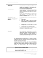
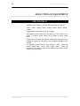
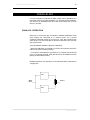
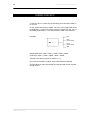
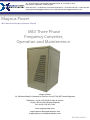
29 - 30 Brunel Road, Churchfields Industrial Estate, St. Leonards-on-Sea
East Sussex. TN38 9RT. United Kingdom
Sales & Service : 01424 853 013 All Other Departments : 01424 853 464 Fax : 01424 852 268
[email protected] [email protected]
Magnus Power
ME3 Three Phase Frequency Converter - Manual
ME3 Three Phase
Frequency Converter,
Operation and Maintenence.
Magnus Power
29 - 30 Brunel Road, St Leonards on Sea, East Sussex, TN38 9RT. United Kingdom
Telephone +44 (0) 1424 853 013 (Sales & Service)
+44 (0) 1424 853 464 (all other Enquires)
Fax +44 (0) 1424 853 2 268
web - www.magnuspower.co.uk
www.magnuspower.co.uk
[email protected]
[email protected]
e-mail - [email protected]
ME3 Manual Rev 1
CONTENTS
1
MAGNUS POWER ME3 SFC
STATIC FREQUENCY CONVERTER
USER MANUAL
2
CONTENTS
CONTENTS
3
CONTENTS
CONTENTS ................................................................................................................................ 3
PRINCIPLES OF OPERATION.................................................................................................. 5
INTRODUCTION .................................................................................................................... 5
START UP AND SHUT DOWN .............................................................................................. 6
RECTIFIER ............................................................................................................................. 7
INVERTER .............................................................................................................................. 8
MICRO PROCESSOR DISPLAY AND FAULT FINDING....................................................... 9
MIMIC PANEL ........................................................................................................................................................ 9
PUSH BUTTONS ................................................................................................................................................. 10
LOGGER DISPLAY.............................................................................................................................................. 12
DIGITAL LCD DISPLAY ....................................................................................................................................... 13
SELECTION OF EQUIPMENT................................................................................................. 16
ME3 MODELS:...................................................................................................................... 16
PARALLELING...................................................................................................................... 17
SIZING THE SFC .................................................................................................................. 18
INSTALLATION ....................................................................................................................... 19
INSTALATION DATA ............................................................................................................ 19
SFC DIMENSIONS (mm) ..................................................................................................................................... 19
INSTALLATION: .................................................................................................................................................. 20
LTDB: ................................................................................................................................................................... 24
ACOUSTICAL NOISE: ......................................................................................................................................... 25
VENTILATION AND AIR CONDITIONING .......................................................................................................... 25
ELECTRICAL CHARACTERISTICS ....................................................................................... 26
ELECTRICAL CHARACTERISTICS ..................................................................................... 26
CABLES SELECTION .............................................................................................................27
CABLES SELECTION .......................................................................................................... 27
HARMONICS FROM RECTIFIER ............................................................................................ 28
4 QUADRANT POWER FACTOR CORRECTED ACTIVE RECTIFIER .............................. 28
4
CONTENTS
EFFECTS OF HARMONICS ON OTHER EQUIPMENT ...................................................... 29
SFC SPECIFICATIONS ...........................................................................................................30
SFC SPECIFICATIONS ........................................................................................................ 30
GUARANTEE ........................................................................................................................... 31
MAINTENANCE AND BACKUP SERVICE .......................................................................... 31
PRINCIPLES OF OPERATION
5
PRINCIPLES OF OPERATION
INTRODUCTION
The ME3 three phase Static Frequency Converter (SFC). guarantees
a supply free of disturbances and of high quality, with maximum
reliability. The use of high frequency pulse width modulation (PWM)
ensures exceptional performance and extremely quiet operation. A 4
quadrant Power Factor Corrected RECTIFIER guarantees lower
input currents, reduced harmonics (THD<5%) and the capability to
handle any type of load including regenerative ones.
The advantages of this technology are:
•
•
•
•
•
Fast response to load changes.
Quiet operation.
Reduction in size and weight.
High efficiency - low heat losses.
Short circuit protection.
If your load is sensitive to mains supply, such as computer Systems,
process electronics, emergency equipment etc., then the SINE33 is
the answer.
The ME3 SFC comprises the following:
•
•
MAINS
INPUT
Rectifier
Inverter
AC
DC
DC
AC
RECTIFIER
INVERTER
SFC
OUTPUT
INTRODUCTION
PRINCIPLES OF OPERATION
6
START UP AND SHUT DOWN
POWER UP SEQUENCE
1.
Switch on “AUX. SUP SWITCH” (Electronics should start up)
2.
Switch on “INPUT MCB”
3.
Switch on ”OUTPUT ISOLATOR”
4.
Switch Inverter on by pressing the Green button.
POWER DOWN SEQUENCE
1.
Switch Inverter off by pressing both Red Buttons simultaneously
2.
Switch off “OUTPUT ISOLATOR”
3.
Switch off “INPUT MCB”
4.
Switch off “AUX.SUP SWITCH”
Any other sequence will not cause any harm to the SFC. Make sure
that the Auxiliary Supply Switch is always ON when operating the
SFC. This will allow the SFC to operate correctly in the event of
Mains Supply dips.
START UP AND SHUT DOWN
PRINCIPLES OF OPERATION
7
RECTIFIER
DC TO INVERTER
MAINS
INPUT
4 QUAD. CONVERTER
The rectifier / charger comprises:
•
•
•
•
•
RFI Filter.
Input triple pole circuit breaker for protection against faults.
MOV input protection against over voltage transients.
LC filter.
4 Quadrant, PF Correction IGBT Bridge.
The Rectifier supplies the Inverter with a constant DC voltage .
The Power Factor Correction IGBT Bridge (4 Quad. Converter)
guaranties input unity power factor and sinusoidal current with low
Harmonic content, as well as 4 quadrant operation.
RECTIFIER
PRINCIPLES OF OPERATION
8
INVERTER
The basic principle of operation of the Inverter is achieved by having
a voltage loop control followed by a current loop control which
maintains the output voltage and wave shape constant and with no
DC offset. To create the sinusoidal wave shape, the DC supply is
switched on and off with varying pulse length (pulse width
modulation). These pulses are then filtered by a LC filter producing a
low distortion sine wave in the output.
DC FROM RECT.
TRANSFORMER
INVERTER
The Inverter consists of:
•
•
•
•
INVERTER
3 Phase IGBT Bridge
L C Filter
Inverter transformer
Control circuitry
OUTPUT
PRINCIPLES OF OPERATION
9
MICRO PROCESSOR DISPLAY AND FAULT FINDING
2
1
1
2
3
4
6
5
7
2
The display panel consists of a digital display, a mimic display, a
diagnosis display, an audible alarm and push buttons
MIMIC PANEL
MIMIC
POSITION
INDICATION
FLAG IN THE DIGITAL DISPLAY
1 -
INPUT FAILURE
“RECTIFIER OFF”
2-
INVERTER OFF
“INVERTER OFF”.
MICRO PROCESSOR DISPLAY AND
FAULT FINDING
PRINCIPLES OF OPERATION
10
PUSH BUTTONS
DISPLAY
POSITION
PUSH BUTTON NAME
PUSH BUTTON FUNCTION
1-
INVERTER ON (green)
It will turn the UPS Inverter ON, if no fault is
present.
2-
INVERTER OFF (red)
To switch the UPS Inverter OFF and transfer
the load to Static Bypass, both red buttons
must be pressed simultaneously.
3-
INDICATION RESET (R)
This pushbutton performs the following
functions simultaneously when pressed:
a) Some fault indications in the Digital Display
will latch when triggered. This push-button will
Reset these indications if the respective fault
has cleared.
b) It Resets the audible alarm.
c) It will reset and restart the Rectifier (only)
after a Rectifier trip.
d)It will exit the Logger display, if in this mode.
4-
FLAG SCROLL UP
If more than two Status flags are present in
the Digital Display, by pressing this button the
flags will scroll up. When there are no more
flags above the “ “ symbol will show next to
the flag. If there are more flags above an
arrow will be seen next to the flag.
To scroll 5 items at a time press this button
and while maintaining it depressed, press the
FLAG SCROLL DOWN also.
5-
FLAG SCROLL DOWN
The same as for the “ Flag Scroll Up “ but in
the downwards direction.
To scroll 5 items at a time press this button
and while maintaining it depressed, press the
FLAG SCROLL UP also.
6-
METER SCROLL UP
Only two readings from the Meter will be
shown at any one time. By pressing this
button the meter readings will scroll up. When
there are no more readings above the “ “
symbol will show next to the last meter
reading. If there are more readings above an
arrow will be seen.
To scroll 5 items at a time press this button
and while maintaining it depressed, press the
METER SCROLL DOWN also.
MICRO PROCESSOR DISPLAY AND
FAULT FINDING
PRINCIPLES OF OPERATION
7-
METER SCROLL DOWN
11
The same as for the “ Meter Scroll Up “ but in
the downwards direction.
To scroll 5 items at a time press this button
and while maintaining it depressed, press the
METER SCROLL UP also.
4-5-6-7
ALL SCROLL BUTTONS
MICRO RESET
Pressing all scroll buttons simultaneously will
reset the Micro.
After reset all LEDs will light up momentarily,
allowing to check faulty ones.
3-4/5
RESET + FLAG SCROLL
LOGGER
By pressing the Reset Button and any of the
Flag Scroll buttons simultaneously, the
display will enter the Logger. In this mode
buttons 4 and 5 will provide a normal scroll
while buttons 6 and 7 will provide a 5 item
scroll.
MICRO PROCESSOR DISPLAY AND
FAULT FINDING
PRINCIPLES OF OPERATION
12
LOGGER DISPLAY
To check the history of the information from the previous section, the Display Logger can be
activated, by pressing simultaneously the Reset button and any of the Digital Scroll Buttons
(left hand side ones). To exit the Logger mode the Reset button must be pressed.
The Display Logger uses all 4 lines of the LCD. An example:
19-10-04
6:30
G4-FE
DIG SIGNALS = 11111110
19-10-05
6:20
G1-EF
DIG SIGNALS = 11101111
Two events are shown. Both happened at the date 19-10-04. The first one at 6:30 and the
fault belongs to group 4 (“Load on Bypass”). The second one happened at 6:20 and the fault
belongs to group 1(“Bat Undervolt”). The zeros indicate the faults that triggered the event.
The next table helps to identify the protections that triggered the events from the information
above (Position 1 = Least Significant Bit).
The left hand side scroll buttons will scroll the logger lines one by one and the right hand side
buttons will scroll 5 lines at a time.
It must be noted that the same information, in a more user-friendly format, is also available
using our Windows based software or a Netagent connection.
Group
Position
G1
1
G2
G3
CHARGER
OVERVOLT
INVERTER SAT
PROT
INVERTER
OVERCURRENT
INVERTER
UNDERVOLT
INVERTER
OVERVOLT
2
ON LINE
EMERG POWER
OFF
CHARGER FAULT
3
MAINS LOW
CHARGER BOOST
4
MAINS HIGH
BAT DISCHARGING
5
BAT UNDERVOLT
RECT OVERVOLT
6
BAT HALF
RECT FAULT
G5
LOAD ON BYPASS
BUTTON ON
MANUAL BYPASS
BUTTON OFF
OUT OF SYNC
REMOTE OFF
FUSE FAILURE
REMOTE ON
BATTERY TEST
-
7
BAT LOW
INVERTER OFF
SHORT CIRCUIT
INV DC OFFSET
DC OUT OF
BALANCE
BAT. EARTH
LEAKAGE
8
CHARGER OFF
UNVERTER FAULT
PHASE ROTATION
OUTPUT ISOLATED
MICRO PROCESSOR DISPLAY AND
FAULT FINDING
OVERLOAD
OVERTEMPERATUR
E
G4
MICRO RESET
-
PRINCIPLES OF OPERATION
13
DIGITAL LCD DISPLAY
METER DISPLAY:
The first two lines of the LCD are used for the Meter functions. They
can be scrolled by the two right hand side buttons.
The following functions are available:
METER FUNCTION
DESCRIPTION
“Inv Volt PH A =”
Phase A Inverter voltage (V).
“Inv Volt PH B =”
Phase B Inverter voltage (V).
“Inv Volt PH C =”
Phase C Inverter voltage (V).
“Op Curr PH A =”
Phase A Output Current (%).
“Op Curr PH B =”
Phase B Output Current (%).
“Op Curr PH C =”
Phase C Output Current (%).
“Input Volt PH A =”
Phase A Input voltage (V).
“Input Volt PH B =”
Phase B Input voltage (V).
“Input Volt PH C =”
Phase C Input voltage (V).
“Input Curr PH A =”
Phase A Input Current (%).
“Input Curr PH B =”
Phase B Input Current (%).
“Input Curr PH C =”
Phase C Input Current (%).
“Pk Op Curr PH A =”
Phase A Peak Output Current (%).
“Pk Op Curr PH B =”
Phase B Peak Output Current (%).
“Pk Op Curr PH C =”
Phase C Peak Output Current (%).
“DC Link Volt =”
DC Link Voltage (V).
“DC Link Curr =”
DC Link Current (%).
“Input Freq =”
Mains Input Frequency (Hz).
“Invert Freq =”
Inverter Frequency (Hz).
“Temperature =”
Cabinet Interior Temperaure
Every single one of these measurements can be eliminated from the
display in the Display Configuration Program.
MICRO PROCESSOR DISPLAY AND
FAULT FINDING
PRINCIPLES OF OPERATION
14
STATUS FLAG DISPLAY / FAULT FINDING
The Status Flag display (3rd and fourth row) provides enough
information for the SFC user to know the operational status of the
SFC, as well as in the case of a fault if a technician should be
contacted.
If no flags are active the third row will show “ Power System OK”. If
any flag is active the flags messages will appear in the third and
fourth rows of the LCD. The left-hand side buttons will scroll the
flags.
The following indications are available:
“Mains Low”
Mains are absent or bellow limits (-20% of nominal).
“Inverter Fault” ; “Inverter Sat
Prot” ; “Inverter Overcurr” ;
“Inverter Undervolt” ; “Inverter
Overvolt”
These indications indicate that the Inverter has been
subjected to high stress such as excessive current
flown through the IGBT’s causing the Inverter to trip.
These indication are self-latching. To clear them, the
“INDICATION RESET” push button ® must be
pressed. If after restarting the Inverter, any of these
indications persist, there is a fault in the Inverter and
the SFC supplier should be contacted. No further
attempts at restarting the Inverter should be made.
“Overtemperature”
The SFC heat sinks’ temperature has exceeded
80ºC. Check if there is any obstruction to the
ventilation inlets or outlets of the SFC and remove it.
If that is not the problem, it is likely that one of the
fans has gone faulty. Contact the SFC supplier.
This indication is self-latching. To reset it, the fault
must be cleared and the “INDICATION RESET”
push button ® pressed.
“Inverter Off”
The SFC Inverter is off. If there is no other fault
indication the Inverter was switched off manually.
“Short Circuit”
When the load current exceeds aproximately 10
times the nominal full load value, the Inverter is
switched off. No SFC output will be available. At this
stage, this indication and the audible alarm are
active. Before trying to reset the SFC, make sure
that the short circuit on the load is removed
“Over Load”
When the load current exceeds 105%, this
indication will be triggered. The Inverter will try to
cope with the overload, being protected by an
inverse time protection: i.e. the larger the overload,
the shorter the time the Inverter will take to switch
off. Typically 1min for a 120% overload and 5
seconds for 150%.
MICRO PROCESSOR DISPLAY AND
FAULT FINDING
PRINCIPLES OF OPERATION
15
“Mains High”
The mains input is out of parameters (greater than
110%). The Power Factor Correction function of the
Rectifier is inhibited. The SFC should not be
operated in this conditions for a long period of time,
since it exceeds its design parameters.
“Phase Rotation”
If the input phase rotation is not correct (R,Y,B), the
indication will be ON. This happens when one of the
phases is swapped around or failed. The Rectifier
will not start.
Normally this type of problem only arises in the
initial installation of the machine and is easily
rectified by swapping around two of the input
phases for the Rectifier Input.
“Rectifier Off” ; “Rect
Overvolt” ; “Rectifier Fault” ;
“DC Offset” ; “DC Out of
Balance”
The following conditions can cause these indications
to be on:
1.
Mains failure.
2.
Mains input breaker in the SFC or Mains
feeding breaker in the distribution box tripped.
3.
Phase rotation on mains input incorrect.
4.
Rectifier fault (DC over voltage or control
voltage failure)
5.
Inverter control failure causing DC Offset
The above anomalies should be corrected as soon
as possible, by calling the SFC supplier.
“Fuse Fail”
When available, this flag indicates one of the SFC
main fuses has failed. Other indications, such as
“Mains Failure” should give an idea of which fuse
has failed. Otherwise a physical observation is
necessary to discover the faulty fuse. This is better
left done by the Maintenance personnel.
The above fault finding information should be enough to solve any
problem that might arise, and should give enough information about
the status of the SFC at any moment.
A remote alarm panel is available, with most of the diagnosis
information of the SFC display panel, with exception of the digital
meter. Also available are a relay interface card with the same
characteristics and a network connection with SNMP protocol via
Netagent, for easier access to all the SFC information.
CONCLUSION:
For the SFC to be in perfect working order, no red indication
should be present on the display panel.
The Status Digital Display should have only the flags “Power
System OK!” and “P.S. Use=” ; the latter indicating the number
of days the SFC has been in use.
MICRO PROCESSOR DISPLAY AND
FAULT FINDING
SELECTION OF EQUIPMENT
16
SELECTION OF EQUIPMENT
ME3 MODELS:
The ME3 range of SFC comes in 8 different ratings as standard:
10KW – 15KW – 20KW – 30KW – 40KW – 50KW – 60KW – 80KW –
100KW.
Single phase output units only go up to 50KW.
For different power ratings from the above, you can consult us for
advice. The above power ratings are for loads of UNITY power
factor.
These units can operate with loads of power factor ranging from 0.2
(leading or lagging) to unity due to the 4 quadrant operation of the
Rectifier.
The standard models cater for input voltages of 400V - 50Hz, with
output voltages 200V - 60Hz ; 480V – 60Hz ; 200V – 400Hz. On
request we can supply machines with different input and/or output
voltages and frequencies.
ME3 MODELS:
SELECTION OF EQUIPMENT
17
PARALLELING
It is also important to note that the ME3 models can be paralleled in a
redundant mode to increase reliability or to increase power capability.
The units to be paralleled must be of the same rating and no more
than 4 in number.
PARALLEL OPERATION
When two or more units are connected in Parallel Redundant mode
their outputs are connected to a common point via a current
equalizing saturable choke as in Figure 16. They also interface with
each other via a CAN Field Bus so that the instructions and controls
are synchronized.
Thus the parallel operation causes the following:
- When the ON button is pressed in one SFC the Inverters of all SFC
will turn ON (with no faults present).
- If one SFC is switched OFF (manually or by a failure) the others will
carry on supplying the load, while the former will be isolated from the
load by its own Static Isolator.
Besides the above, the operation of the Individual SFC is identical to
a single SFC.
SFC 1
MAINS
INPUT
OUTPUT
SFC 2
PARALLELING
SELECTION OF EQUIPMENT
18
SIZING THE SFC
To size the SFC in a safe way the following points should be taken in
to account:
All the peak loads must be added. The sum of the peak loads must
be divided by 1.5 and if the result is equal or larger than the sum of
the steady loads times 1.2, this result must be used in the selection.
Example:
5KW
3KW
(Peak=12KW)
SFC 1
15KW
(Peak=30KW)
6KW
Steady state load = 5KW + 3KW + 15KW + 6KW = 29KW
Peak load = 5KW + 12KW + 30KW + 6KW = 53KW
53KW/1.5=35.3KW (Larger than 29KVA x 1.2)
Since the next model is a 40KW, this model should be selected.
This will allow for start up and peak currents and will provide a power
margin of 20%.
SIZING THE SFC
INSTALLATION
19
INSTALLATION
INSTALATION DATA
SFC DIMENSIONS (mm)
SFC MODEL
ENCLOSURE
WIDTH
DEPTH
HEIGHT
40K – 50K
SINE33-710
710
800
1400
60K – 100K
SINE33-1400
1400
800
1400
SINE33-1400
FRONT
SIDE
SINE33-710
INSTALATION DATA
INSTALLATION
20
SFC MODEL
10K – 30K
ENCLOSURE
WIDTH
LENGHT
HEIGHT
SINE33-NC
530
750
990
The ME3 SFC, due to its compact size and quietness of operation,
can operate in a computer room environment, on a false floor or
normal level floor.
INSTALLATION – 10-15KW:
The 10KW - 30KW Units – are shown above. The units should be
installed in a well ventilated area or room, since in spite of very good
efficiency heat is still generated.
INSTALLATION – 40-100KW:
All units are front access, which facilitates maintenance and saves
space. The units don’t need back or side clearance, but care must be
taken not to block the top, for proper ventilation.
The units should be installed in a well ventilated area or room, since
in spite of very good efficiency heat is still generated.
Users have access to the SFC Switch Gear Via the bottom door that
has a Key Lock.
INSTALATION DATA
INSTALLATION
21
The interior of the SFC should only be accessed by trained
technical personnel after complete shut down and a waiting
period of at least 10 min to allow the DC capacitors to
discharge.
The sequence to open all the SFC panels is as follows:
1. Open the bottom door and unscrew the top door (bottom left
hand side).
2. Open the top door and will have access to all the SFC
components that may need maintenance.
3. Unscrew the top panel (front), via the round apertures at the
inner protection plate, and remove it pulling upwards and to the
front.
4. With the top removed the magnetics cooling fans are accessible.
INSTALATION DATA
22
INSTALLATION
5. Unscrew the side and back panels (top) and remove them by
pulling towards you and lifting them. They are secured to the
uprights by wedges. The panels have inside handles to help
remove and replace them.
Units with external batteries can have remote temperature
compensation (optional).
The standard external battery cabinets open in a similar way as the
UPS except that they have a single door in the front and don’t have a
top inner protection plate.
INSTALATION DATA
INSTALLATION
23
POWER TERMINALS:
The power terminals are accessed via the bottom front door that has
a key lock. With units up to 50KW (SINE33-710 cabinets) another
protection plate at the MCB assembly must be removed.
The Input & Output cables are fed to the SFC via the bottom gland
plate that is placed next to the Power Terminals. Care must be taken
to terminate the cables correctly to avoid damage to the SFC.
Mistakes like connecting the Input cables to the Output
Terminals can damage the SFC in spite of its protections.
Units with Top Cable Entry (optional) will have the Power Terminals
on the top inner protection plate, with the cable glands installed at the
back of the SFC. This type of unit must be ordered from factory as
Top Entry.
INSTALATION DATA
INSTALLATION
24
LTDB:
A low-tension distribution board must be provided by the customer, to
feed the SFC and the user’s load.
The input circuit breaker (feeding the SFC) should be of at least the
same rating and of the same type as the “RECTIFIER MCB” breaker
in the SFC.
For the output circuit breakers the ratings are dependent on the
specific load each of the breakers is feeding. The SFC will be able to
clear a B type MCB of at least 33% of the Full Load Current, without
tripping the Inverter.
The diagram illustrates an installation with separate supplies in the
input section
MAINS
INPUT
LTDB
LOAD
SFC
With larger units, where considerable currents flow in the input and
output cables, these must be carefully laid so that the magnetic field
they produce does not interfere with other equipment such as
screens, magnetic card readers, etc.
INSTALATION DATA
INSTALLATION
25
ACOUSTICAL NOISE:
The ME3 range of SFC is extremely quiet, making it ideal for use in
the office or computer room. The emitted noise is less than 55 dBA.
VENTILATION AND AIR CONDITIONING
The ME3 range of SFC is designed to operate at an ambient
temperature of up to 40ºC at sea level. For 2000m altitude the
operating ambient temperature should not exceed 30ºC.
Since there are heat losses in the SFC, care must be taken in
providing the correct ventilation or air-conditioning for the room
where the SFC is going to be installed.
The following table provides information about the heat losses of the
various models for 100% load at 1 power factor .
UNIT POWER
HEAT LOSSES (100% Load)
10KW
1.1KW
15KW
1.65KW
20KW
2.2KW
30KW
3.3KW
40KW
4.4KW
50KW
5.5KW
60KW
6.6KW
80KW
8.8KW
100KW
11KW
INSTALATION DATA
ELECTRICAL CHARACTERISTICS
26
ELECTRICAL CHARACTERISTICS
ELECTRICAL CHARACTERISTICS
The following table gives the electrical characteristics of the ME3SFC for an input voltage of 400V, output voltage of 200V and full
load at 1 power factor.
ME3 MODEL
3 phase
MAX INPUT
CURRENT
OUTPUT
CURRENT
VDC
10K
15K
20K
30K
40K
50K
60K
80K
100K
17A
26A
34A
51A
68A
85A
102A
136A
170A
29A
43A
58A
43A
87A
109A
130A
174A
217A
750
750
750
750
750
750
750
750
750
ELECTRICAL CHARACTERISTICS
CABLES SELECTION
27
CABLES SELECTION
CABLES SELECTION
ARMORED CABLE FREE
UNARMORED CABLE
AIR WIRED
FREE AIR WIRED
27 Amps
24 Amps
4,0mm 2
35 Amps
32 Amps
6,0mm 2
43 Amps
41 Amps
10mm 2
60 Amps
55 Amps
16mm 2
70 Amps
72 Amps
25mm 2
100 Amps
94 Amps
35mm 2
125 Amps
115 Amps
50mm 2
150 Amps
140 Amps
70mm 2
180 Amps
175 Amps
95mm 2
225 Amps
215 Amps
2,5mm 2
Suggested maximum currents
CABLES SELECTION
HARMONICS FROM RECTIFIER
28
HARMONICS FROM RECTIFIER
The ME3 SFC uses a 4 Quadrant Active Power Factor Control
rectifier/charger with unity power factor correction and sinusoidal
input current to minimize the effect of harmonics upstream of the
SFC installation. Input RFI filters are also fitted as a standard in every
model to comply with EN50091-2:1995 (EMC) AND IEC61000-34:1998 (Harmonics).
4 QUADRANT POWER FACTOR CORRECTED ACTIVE
RECTIFIER
DC TO INVERTER
MAINS
INPUT
BATTERY
4 QUAD. CONVERTER
The 4 Quadrant capability of the ME3 Rectifier allows the SFC to
handle a larger range of difficult loads such as induction motors in
regeneration mode and high capacitive circulating currents, which
could cause serious problems with standard SFC.
By using this topology not only the input Power Factor is corrected to
very close to unity, improving the energy bills, but the current
harmonics are greatly reduced (THD<5% at full Load).
4 QUADRANT POWER FACTOR
CORRECTED ACTIVE RECTIFIER
SFC SPECIFICATIONS
29
EFFECTS OF HARMONICS ON OTHER EQUIPMENT
The presence of current harmonics in the Mains can disrupt the
operation of equipment connected to it:
•
•
•
•
•
It can affect the sizing of generating sets feeding the SFC.
Increases the losses in transformers, motors and other
inductive equipment.
Increases currents
equipment.
through
power
factor
correction
Interfaces with measuring instruments, telephone circuits, and
sensitive equipment.
The ME3, with its built in power factor correction minimizes
the above mentioned problems.
EFFECTS OF HARMONICS ON OTHER
EQUIPMENT
SFC SPECIFICATIONS
30
SFC SPECIFICATIONS
SFC SPECIFICATIONS
INPUT:
4 Wire (3 Wire optional)
3 Phase 400V/415V AC ...................................................... -20%+10% *
50.0Hz ................................................................................ ± 5% *
Input Current Harmonics .................................................... <5% at Full Load (Sinusoidal)
OUTPUT
3 Phase200V/ 400V/415V/ AC-60.0 HZ/400Hz .................. ± 1% *
1 Phase115V/ 230V/240V/ AC-60.0 HZ/400Hz .................. ± 1% *
Overall Efficiency ................................................................ 85%-90%
Max. Crest Factor .............................................................. 3:1
RECTIFIER
4 Quadrant Operation
Efficiency ............................................................................ 93%-95%
Input Frequency Deviation .................................................. 5%
Overload Capacity .............................................................. 120% Continuous
Current walk in .................................................................... 2 second to maximum
Overall Current Limit ........................................................... 115%
Short Circuit Proof .............................................................. Standard
INVERTER
Static regulation 0 - 100% load ........................................... ± 0.5%
Dynamic regulation 100% load application/removal
Transient Recovery ......................................... 5%, recovering to 1%
......................................................................... within 5 millisecond
Total harmonic distortion .................................................... Better than 3% (Linear load)
Overload capacity ............................................................... 120% (Limited to 1 Min)
Frequency stability 50.0 Hz ................................................ ± .01% crystal controlled
Load power factor ............................................................... 0.2-1
Efficiency ............................................................................ 93%-95%
Short circuit proof by electric current limiting and shutdown
COMMUNICATIONS
RS232/RS485 ..................................................................... Standard with Windows Software
Ethernet Connection ........................................................... Standard with Netagent
CAN (With Remote Panel) .................................................. Optional
ENVIRONMENTAL CONDITIONS:
Temperature range 0/40 degrees Celsius .......................... At sea level (full load)
............................................................................................ 30º Celsius at 2000m (full load)
Humidity: Recommended ................................................... 40% to 60%
Extreme ........................................................... 0% to 90%
Noise level .......................................................................... below 55 dBA at 1 meter
Altitude................................................................................ Up to 2500m
* Other Voltages and Frequencies available on request
SFC SPECIFICATIONS
GUARANTEE
31
GUARANTEE
All Magnus Power equipment is guaranteed against faults
attributable to faulty design, components and workmanship whilst
operating under normal conditions for a period of 12 months from
date of delivery. During this period all faulty components will be
replaced free of charge. Accommodation and traveling costs involved
therein shall be for the customer account. All call-outs which cannot
be attributed to faults or malfunctions on our equipment, shall be
charged at our standard service rates and be for your account. Our
liability under our guarantee is limited to the above and we do not
accept any responsibility for any consequential loss.
MAINTENANCE AND BACKUP SERVICE
All spares are available locally and we guarantee stock for ten years.
The combination of spares availability and factory trained service
personnel should ensure that no unit is out of order for more than 48
hours after receipt of report of malfunction/failure. At the expiry of the
guarantee period, we can service the unit on a continuous base, but
this would necessitate the negotiation of a separate agreement.
MAINTENANCE AND BACKUP SERVICE
29 - 30 Brunel Road, St Leonards-on-Sea, East Sussex, TN38 9RT. United Kingdom
Sales - 01424 853013 - All Other Departments - 01424 853464 - Fax - 01424 852268
Registered in England, Registered office Unit 12, Clivemont Road, Cornwallis Ind. Est. Maidenhead SL6 7BZ.
Registration No. 4977339. VAT Registration No. GB 829 4203 28