1
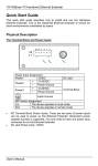
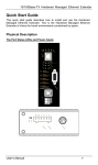
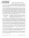
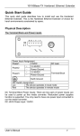
TS Series
TRUNKSAFE® Fault-Tolerant Fieldbus System
July 2013
Description
The TRUNKSAFE Fault-Tolerant Fieldbus System
provides a cost-effective, yet highly reliable, strategy
to maintain continuous communications between
field devices and a host system in the event of any
single point failure (such as any open single wire)
on a FOUNDATION fieldbus™ H1 or PROFIBUS PA
segment.
Delivers “High-Availability” Fieldbus Segments
Designed for important and plant-critical fieldbus
segments, TRUNKSAFE utilizes two trunk cables (or
“legs”) for physical layer redundancy to ensure no
single point of failure will shut down the network.
Under normal operation, the fieldbus segment is terminated at each end of the segment at
the TRUNKSAFE Redundant Power Conditioners.
TRUNKSAFE maintains fieldbus communications
throughout the entire segment until a fault (open- or
short-circuit) is detected. Upon fault detection, the
TRUNKSAFE Device Coupler initiates its automatic
segment termination so that the healthy leg is properly terminated. This patented*, automatic system for
fault detection and termination allows uninterrupted
fieldbus communications throughout the segment
(see Figure 1). The host is informed about the fault
via a contact closure output.
TRUNKSAFE is fully compliant with
FOUNDATION fieldbus FF831-1 (the technical specification for fieldbus power supplies) and FF846-1 (the
technical specification for device couplers).
Fault-Tolerant Protection Against
All Physical Layer Faults
One difficulty still remains with fieldbus technology:
all segment communications and power integrity
are vulnerable to a single broken twisted wire
cable. Until now, the only ways to protect plantcritical segments were expensive duplication of
an entire segment’s hardware, complex software
voting schemes and restricting the number of
devices per segment. With TRUNKSAFE, critical
process loops can use fieldbus technology without worrying about cable failures. This allows full
access to advanced diagnostics and uninterrupted
measurement and control communications that
can be realized using fieldbus technology.
* United States Patent Numbers 7,454,252 and 7,505,819
All product names are registered trademarks of their respective companies.
© 2013 Moore Industries-International, Inc.
920156D
TRUNKSAFE Fieldbus Device Couplers and Power
Conditioners install on a DIN-style rail. Device couplers can be
ordered in rugged field-mount enclosures with cable glands.
Features
• Complete redundant fieldbus physical layer.
TRUNKSAFE is comprised of a Host Interface,
two redundant fieldbus DC Power Conditioners
and a specially-engineered Device Coupler that,
in combination, maintain continuous segment
communications even in the event of a cable break
(open- or short-circuit) or failures to a TRUNKSAFE
Power Conditioner.
• Compatible with FOUNDATION Fieldbus H1 and
PROFIBUS PA networks. Completely compliant
with fieldbus physical layer standard IEC 61158-2;
no modification is required to fieldbus devices or to
DCS-level software.
• Advanced Fieldbus physical layer diagnostics.
TRUNKSAFE Diagnostic Modules offer simple
hardware-based alarm LEDs and voltage free
relay for DC power status, segment noise, power
conditioners and network status.
Certifications
Factory Mutual (cFMus) US/Canada
File No. 3032513C
Non-Incendive - Class I, Division 2,
Groups A, B, C, D; T4A Ta=70°C
ATEX
Certificate No. MII13ATEX0002X
II 3 G Ex nA nC [ic] IIC T4
Ta: –40°C to +70°C
IECEx
Certificate No. FMG 08.0007X
Ex nA nC [nL] IIC T4
CE Conformant — EMC Directive 2004/108/EC EN
61326
Page 1
TS Series
TRUNKSAFE® Fault-Tolerant Fieldbus System
Figure 1. TRUNKSAFE maintains continuous segment communications between field devices and a host system in the event of any single
point failure, such as an open- or short-circuit.
Available Host Interface Kits accommodate the
specific architectures of host specific configurations.
These provide a seamless connection to the
redundant physical H1 layer without affecting
host hardware or software. (See the TRUNKSAFE
User’s Manual for details.)
DCS
Redundant
H1 or PA
Interface
Moore
Industries
Host Interface
Kit
Two
Fieldbus
“Legs”
Trunk Cable B (less than 30m)
Termination
is NOT ACTIVE
+
S
Termination
is ACTIVE
Auto-detects system and
field cable failure and
then prevents
communications on
that side of the trunk
-
SPM201
Surge Protection
Module (optional)
Total cable length
per segment can be up to
1,900m (6,233ft), with a
maximum of 1,000m
(3,280ft) trunk on one side
+
Uninterrupted
Fieldbus Segment
Communications
Cable lengths on each
side do not need
to be balanced
TS206
TRUNKSAFE
Device Coupler
-
Up to 350mA of
isolated, redundant
and conditioned
power per segment
LED ON indicates
active trunk status
+ S
+ S
+ S
+ S
+ S
+ S
TRUNK
B
+ S
FF/PA
Devices
Field Enclosure
(optional)
Auto-Termination is ACTIVE
TRUNKSAFE’s Automatic Segment Termination
is initiated upon fault detection
on either side of the trunk
Page 2
S
TPS202 Advanced
Power Conditioner Module
FDM252
On-board Diagnostics
Module provides
comprehensive fieldbus
physical layer diagnostics
+ S
BREAK!
T
TPS201-4
TRUNK
A
T
TPS201-4 Power
Conditioner DIN Carrier
Trunk Cable A (less than 30m)
TS Series
TRUNKSAFE® Fault-Tolerant Fieldbus System
Simple, Yet Secure, Redundancy
The TRUNKSAFE Fault-tolerant Fieldbus System is
comprised of three main sections: a Host Interface Kit (with
Fieldbus Redundancy Adaptors), two fieldbus DC Power
Conditioners, and a single field-based Device Coupler
(Figure 1). TRUNKSAFE’s major advantage is that no
single point of failure will cause the loss of fieldbus communications with the host system.
TRUNKSAFE’s Host Interfaces are unique to each host
system, since each supplier has their own method of supporting redundant H1 cards or a PA coupler. The
TRUNKSAFE concept is to convert these single H1 or PA
trunk outputs into two trunk outputs that will be carried all
the way to the Device Coupler in the field. Typically this is
done with Fieldbus Redundancy Adapters connected on
the host H1 cards or terminal board (See the TRUNKSAFE
User’s Manual for details). Additional Fieldbus Redundancy
Adapters (when needed) ensure that active modules can be
replaced without shutting down H1 or PA communications.
The resultant two trunk outputs begin the redundant
H1 segment, and are then wired to separate TRUNKSAFE
Power Conditioner DIN Carriers (TPS201). In most cases
this is accomplished with a plug-to-plug cable connector
carrying four segments. Each segment has two trunks, and
each trunk is connected to a separate Fieldbus Power Conditioner DIN Carrier Board. Each Carrier Board supports
four trunks with an individual Power Conditioning Module
(TPS202) for each trunk. The segment has redundant
Power Conditioner Modules (one on each DIN Carrier
Board) providing conditioned power to the trunk and fieldbased Device Coupler. The Device Coupler receives power
and communications from each trunk. In normal operation,
integral fieldbus terminators are provided at each Power
Conditioner Module.
Completely compliant with IEC 61158-2, the system
will support a total cable length including the redundant leg
and spurs of up to 1,900 meters (6,233 feet).
Reaction to Cable Fault Detection
TRUNKSAFE provides industry-first secure communications for a fieldbus network.
Advanced Redundant Power Conditioners—Both of
TRUNKSAFE’s Power Conditioners continuously monitor its
segment cable leg. In the event of a field cable (open-circuit, short-circuit or broken wire) or host failure, the Power
Conditioner immediately detects, reports and isolates the
faulty leg. System communications will continue over the
remaining leg.
Device Couplers with Fully-Automatic
Segment Terminator—The TRUNKSAFE Device Coupler
simultaneously detects the absence of DC power on the
incoming trunk as a cable fault on one leg, and activates
its terminator. This maintains normal fieldbus communications on the healthy leg. Internal blocking circuitry prevents current flow out of the device coupler so that a trunk
short-circuit on one side cannot affect the trunk on the
other side. The TRUNKSAFE Device Coupler automatically
resets when cable integrity is restored. This functionality
allows TRUNKSAFE to maintain all fieldbus communication
functions in spite of any single system fault, and provide for
automatic reset once the faults are removed.
TRUNKSAFE Advanced Fieldbus Power
Conditioner
The TRUNKSAFE Power Conditioner is composed of a
TRUNKSAFE DIN Carrier (Model TPS201) populated with
up to four TRUNKSAFE Advanced Power Conditioner
Modules (Model TPS202). Each Power Conditioner provides up to 350mA of isolated and conditioned DC power
for FOUNDATION fieldbus H1 or PROFIBUS PA segments.
The system’s power conditioner pairs are fully load-sharing
in normal operation. Each also incorporates a hard-wired
segment terminator that is always ON.
Physical Layer Diagnostics—The TRUNKSAFE system
incorporates a diagnostics module which maintains overall
system “high-availability” by giving advance notice of cable
faults as well as potential failures (See Page 6 for additional
information).
TRUNKSAFE Fieldbus Device Coupler
Available in 6- and 12-spur configurations, TS200 Device
Couplers have designed in redundancy and feature:
Automatic Segment Termination—TRUNKSAFE
delivers the unique advantage of being able to identify a
open- or short-circuit, isolate the faulty leg, and automatically terminate the leg of the TRUNKSAFE system that
continues operating normally.
Short Circuit Protection—TRUNKSAFE Device
Couplers provide electronic and fully auto-resetting spur
short-circuit protection that prevents segment failure caused
by single device faults. Utilizing a “FoldBack” technique,
any spur that attempts to draw more than 48mA is automatically switched off and not permitted any current flow
until the fault is removed. This is a significant advantage
over “current-limiting” designs on competing units which
hold a fault permanently on the segment at a higher than
normal current level. This often results in segment failure
by overloading the segment power supply. With removal of
the short, the TRUNKSAFE Device Coupler automatically
reconnects the spur to the fieldbus segment.
Diagnostic LEDs and hand-held connections—
Diagnostic LEDs positively indicate status of each incoming
trunk, power status on each spur, spur short circuits and
status of auto termination. The front panel features convenient connections for a fieldbus hand-held configurator (see
Page 6).
Page 3
TS Series
TRUNKSAFE® Fault-Tolerant Fieldbus System
Specifications
TRUNKSAFE Advanced Fieldbus Power Conditioner
Performance
Terminals
Performance
Indicators
TPS201-4 Power
Conditioner DIN Carrier
Number of Segments: 4
Supply Voltage: 19.2 to
32Vdc, reverse polarity
protected
Performance
LED
Indicators
Type: Removable
terminals with screwclamp retaining screws
Wire Size: Handles
0.8-2.5mm2/12-24AWG
cable sizes
TPS202 Power
Conditioner Module
Output Capacity:
350mA per segment;
up to 25.5V (no load)
Power Requirements: 13.5VA @350mA per
segment
Power Dissipation: 5.5W @350mA per
segment
Terminator:
100 ohms/1microFarad
per segment
DC/DC Isolation: 500Vdc (segment to
power supply)
Alarm Relay
Output
FDM252 Fieldbus
Diagnostics Module
Power Dissipation:
0.5W maximum
Performance
LED Type: GREEN,
Normal; RED, Fault
LED A: DC “A” Input
Voltage Low (<18V)
LED B: DC “B” Input
Voltage Low (<18V)
LED 1: Segment #1
Noise High
(>75mV p/p)
LED 2: Segment #2
Noise High
(>75mV p/p)
LED 3: Segment #3
Noise High
(>75mV p/p)
LED 4: Segment #4
Noise High
(>75mV p/p)
Type: Relay (failsafe,
open on alarm)
Contact Rating:
5A@250Vac 50/60Hz
or 24Vdc, non-inductive
load
LED (Power): GREEN,
normal; ORANGE, Output
Voltage <18V
LED (Short): GREEN,
normal; RED, Cable Short
LED (Open): GREEN,
normal; RED, Cable Open
Ambient
Conditions
(All
Components
and Options)
SPM201 Surge
Protection Module
Complies with:
-IEC 61158-2, for
31.25kB/s and testing
according to
-IEC 61643-21
Maximum Surge
Current Isn: 20kA
(8/20μsec)
Nominal Discharge
Current Isn:
3kA(8/20μsec)
Nominal Rated Current
In: 650mA
Maximum Continuous
Operating Voltage
(MCOV): 35V
Peak Common Mode:
230V
Limiting Voltage Vlim:
50V@3kA (8/20μsec)
Nominal Voltage Vn: 32V
Line Attenuation: Rs: 1
ohm capacitance:1nF
IP Rating: IP20
Operating Range: –20°C to +60°C
(–4°F to +140°F)
Storage Range: –40°C to +85°C
(–40°F to +185°F
Relative Humidity: 0-95%, non-condensing
RFI/EMI Immunity: 10V/m@80-1000MHz,
1kHz AM when tested
according to IEC61326
TRUNKSAFE Fieldbus Device Coupler (TS200)
Communications
FOUNDATION
Fieldbus™ H1 or
PROFIBUS PA
Performance
Maximum Quiescent
Current:
TS206: 13.5mA
TS20W: 25mA
Maximum Spur Output
Current: ISlim=48mA
Spur Short Circuit
Load: ISsc
2mA (typical)/6mA max.
Spur Voltage Drop:
0.5V@20mA spur
current (typical), 1V
maximum
Maximum Spur Voltage:
24V max. no load
Page 4
LED
Indicators
Terminals
Enclosures
(Optional)
Trunk: GREEN (Active);
OFF (Inactive)
Spur: GREEN (Normal);
RED (Fault)
Auto-Terminator:
YELLOW (Terminator On);
OFF (Terminator Off)
Type: Removable
terminals with screwclamp retaining screws
Wire Size: Handles
sizes between
0.8-2.5mm2/12-24AWG
Type: Aluminum IP66;
Stainless Steel 316 IP66;
GRP (Glass Reinforced
Polyester) IP66
Cable Gland
(Device
Couplers with
Enclosures)
Ambient
Conditions
Type: Armored/
Unarmored
Material: Nickel-plated
brass
Operating Range:
–40°C to +70°C
(–40°F to +158°F)
Storage Range:
–40°C to +85°C
(–40°F to +185°F)
Relative Humidity:
0-95%, non-condensing
RFI/EMI Immunity:
10V/m@80-1000MHz,
1kHz AM when tested
according to IEC61326
TS Series
TRUNKSAFE® Fault-Tolerant Fieldbus System
Ordering Information
TRUNKSAFE Advanced Fieldbus Power Conditioner and Associated Accessories
Description
Model Number
TPS201-4
TRUNKSAFE Advanced Power Conditioner DIN Carrier (Handles up to 4 TPS202 Advanced Power Conditioners)
TRUNKSAFE Advanced Power Conditioner Modules (Specify up to 4 per TPS201-4 DIN Carrier)
TRUNKSAFE Fieldbus Diagnostics Module (One module per TPS201-4 DIN Carrier)
TPS202
TRUNKSAFE Surge Protection Module (Optional, one per active segment requiring protection)
FDM252
SPM201
TRUNKSAFE Fieldbus Device Coupler
Unit
TS2
TRUNKSAFE
Fault-Tolerant
Fieldbus System
Mounting/
Enclosure Type
Number of Spurs
Gland Connector Type
Gland Entry Size
Certification
-ATEX For use in
Zone 2 with [ic]
spurs
0 DIN-Rail Mount
(No enclosure;
for installation
in another
manufacturer’s
enclosure; IP54
protection is
recommended)
6 Fieldbus Spurs
W 12 Fieldbus Spurs
Not Applicable
-DIN (No cable glands)
Universal DIN-style
enclosure mounts on
32mm (EN50035)
G-type and 35mm
(EN50022) Top Hat
DIN-rails
5 Standard
Aluminum, Solid Cover, IP66 Enclosure
6 Standard
Aluminum, Clear Cover, IP66 Enclosure
4 Stainless
Steel 316, IP66 Enclosure
with E-Z vertically
removable lid and
bottom entry cable
gland plate
6 Fieldbus Spurs
W 12 Fieldbus Spurs
-A Unarmored Cable
Glands (standard)
-B Armored Cable Glands
-C Compound Seal Cable Glands
-D No Cable Glands
-E M12 Turck Eurofast ™
Sockets
-F 7/8-in. Turck Minifast ™
Sockets
GLAND ENTRY SIZE
FOR:
-O (standard)
Unarmored Cable
(7.5-11.9mm O.D.);
Armored Cable
(9.5-16.0mm O.D.)
3 GRP (Glass
Reinforced
Polyester), IP66 Enclosure
6 Fieldbus Spurs
When ordering, specify: Model number example: NOTES:
1. Gland/connector selection is for
all entry ports.
2. Choices “-E” and “-F” have
male sockets for “Trunk In” and
female sockets for “Trunk Out” and
“Spurs”.
3. Weatherproof seals are
provided for all glands, but not
sockets.
4. Compound seal glands are
epoxy filled on installation and
prevent gas transmission into
enclosures; no seal pot required
from Division 1 to Division 2.
-S Unarmored Cable
(3.0-8.0mm O.D.);
Armored cable
(5.5-12.0mm O.D.)
Unit • Mounting or Enclosure Type • Number of Spurs -Gland/Connector Type -Gland Entry Size
TS256-DIN-ATEX
(6-Spur Device Coupler in Aluminum Enclosure with Cable Glands for Unarmored Cable with ATEX Certification)
Typical TRUNKSAFE Bill of Materials (for single segment TRUNKSAFE network):
1 ea. Host Interface Kit
2 ea. TPS201-4
2 ea. TPS202
2 ea. FDM252
2 ea. SPM201
1 ea. TS256-A-0
Host Interface Kit (See the TRUNKSAFE User’s Manual for Details)
4-Position TRUNKSAFE Advanced Power Conditioner DIN Carrier
TRUNKSAFE Power Conditioner Module
TRUNKSAFE Fieldbus Diagnostics Module
TRUNKSAFE Surge Protection Module
6-Spur TRUNKSAFE Device Coupler in Aluminum Enclosure with Cable Glands for Unarmored Cable
Page 5
TS Series
TRUNKSAFE® Fault-Tolerant Fieldbus System
Intelligent Physical Layer Diagnostics
The TRUNKSAFE Redundant Fieldbus System
delivers comprehensive diagnostic capabilities at
every level.
Power
Supply Diagnostics
LEDs on the TRUNKSAFE Power Conditioner
Modules alert users to potential problems:
• Host or field cable open-circuit
• Host and field cable short-circuit
• High field current (>350mA)
• Low Power Conditioner output voltage (<18V)
The TRUNKSAFE Diagnostic Module provides
additional information on vital parameters influencing
the physical layer. A volt-free contact closure can be
wired as a general alarm, with individual LEDs on the
Diagnostic Module reporting the following faults:
• DC Input Voltage #1 Low (<18V)
or Loss of Input Supply
• DC Input Voltage #2 Low (<18V)
or Loss of Input Supply
• Segment #1 Noise High (>75mVpp)
• Segment #2 Noise High (>75mVpp)
• Segment #3 Noise High (>75mVpp)
• Segment #4 Noise High (>75mVpp)
NOTE: Advanced Diagnostics
Advanced physical layer diagnostic modules with
communications to a host are available from several
vendors. We suggest selective use of this capability
tied to control or critical segments. Third-party DINrail mounted Advanced Diagnostic Modules can easily
be attached to any MooreHawke segment. Consult
the factory for details.
Fieldbus Redundancy Adaptor
A TRUNKSAFE host-specific Fieldbus Redundancy
Adaptor installs between the H1/PA interface card(s)
and the TRUNKSAFE Power Conditioner DIN Carrier
Board, and routes the fieldbus signal to both trunks of
the TRUNKSAFE network. The Fieldbus Redundancy
Adaptor and Interface Adaptor (if necessary) has no
effect on the operation or performance of the H1/PA
cards, and is typically mounted in close proximity to
the H1/PA card or module.
TRUNKSAFE Fieldbus Host Interface Kits are available to accommodate the architectures of the major
host manufacturers including ABB, Emerson Process
Management, Honeywell, Invensys, Siemens and
Yokogawa. A generic redundancy adaptor is also
available to accommodate other host suppliers or
when a single H1 Card or PA Coupler is used in a
host system.
Surge Protection Module
The SPM201 Surge Protection Module prevents
surges and over voltage spikes occurring directly on
the main trunk from causing damage to the TRUNKSAFE Power Conditioner Modules, as well as the host
system.
Inserted onto the field side pluggable terminal
position, the SPM201 is fitted with a combination of
solid state electronics and a gas discharge tube to
withstand a surge of up to 20kA. It diverts surges to
a safe earth connection, with no effect on the performance of the TRUNKSAFE Power Conditioner. All
TRUNKSAFE Power Conditioner Carriers (TPS201-4)
fitted with SPM201 Modules must have a secure
low-impedance (<0.1 ohm) connection to the main
local ground.
Figure 2. SPM201 schematic.
Device Coupler Diagnostics
LEDs on the TRUNKSAFE’s Device Couplers provide
instant indication of:
• Power status each TRUNK
• Power status per SPUR
• Short-circuit status per SPUR
• Auto-termination ON/OFF
NOTE: The TRUNKSAFE system provides complete fault tolerant
segment communications independent of the TRUNKSAFE Diagnostics Module. However, all advanced diagnostics and all alarms
require the Diagnostics Module to be specified with the system.
Page 6
(+)
a
s
TO FIELD
b
Gas
Discharge
Tube
TO POWER
CONDITIONER
( )
(s)
a
s
Gas
Discharge
Tube
TS Series
TRUNKSAFE® Fault-Tolerant Fieldbus System
Figure 3. TPS201/202 Advanced Power Conditioner with DIN-Rail
Mounting Installation Dimensions.
Figure 4. TS200 Device Coupler DIN-Rail Mounting Installation
Dimensions (Base Unit).
216mm
(8.50 in)
127mm
(5.00 in)
6-Spur (Shown)
204mm
(8.05 in)
12-Spur
TOP VIEW
TOP VIEW
TPS200
114mm
(4.50 in)
82mm
(3.23 in)
121mm
(4.77 in)
SIDE VIEW
51mm
(1.99 in)
SIDE VIEW
(Shown with SPM
Surge Protection
Module Installed)
Figure 5. Standard Aluminum Enclosure Installation Dimensions for 6-Spur (TS256) and 12-Spur (TS25W) Models.
175mm
(6.89 in)
322mm
(12.68 in)
156mm
(6.14 in)
274mm
(10.79 in)
GROUND STUD
SCREW
#10-32
DIA. 4.8mm
(0.190 in)
293mm
(11.54 in)
367mm
(14.45 in)
107mm
(4.21 in)
Page 7
TS Series
TRUNKSAFE® Fault-Tolerant Fieldbus System
Figure 6. Stainless Steel 316 with E-Z Vertically Removable Lid and Bottom Entry Cable Gland Plate 12-Spur Models (TS24W).
35mm (1.50 in)
Model No :
Serial No :
Tag No :
TRUNKGUARD
Series 200 Device Coupler
Moore Industries-International North Hills CA, USA
319mm
(12.56 in)
FOR PLASTIC ENCLOSURES:
CLEAN ONLY WITH DAMP CLOTH
MIN CLEARANCE
FOR LID
REMOVAL
260mm
(10.24 in)
Padlock fixing
GROUND STUD M10
DIA. 10mm (0.394 in)
224mm
(8.82 in)
183mm
(7.20 in)
248mm
(9.76 in)
REMOVABLE GLAND PLATE
135mm x 175mm
(5.31 in x 6.89 in)
PRE-DRILLED
M20 ENTRIES 2x PLATES
Figure 7. GRP (Glass Reinforced Polyester) Enclosure Installation
Dimensions for 6-Spur (TS236) Models.
Figure 8. TS2XX-DIN with -ATEX option
TOP VIEW
204mm
(8.05 in)
12-Spur
Model No :
Serial No :
Tag No :
TRUNKSAFE
Series 200 Device Coupler
244mm
(9.60 in)
Moore Industries-International North Hills CA, USA
FOR PLASTIC ENCLOSURES:
CLEAN ONLY WITH DAMP CLOTH
127mm
(5.00 in)
6-Spur (Shown)
82mm
(3.23 in)
260mm
(10.24 in)
Shown with
Unarmored
Cable Glands
140mm
(5.51 in)
160mm
(6.30 in)
105mm
(4.13 in)
SIDE VIEW
73mm
(2.90 in)
55mm
(2.17 in)
51mm
(1.99 in)
• www.miinet.com
Page 8
United States • [email protected]
Tel: (818) 894-7111 • FAX: (818) 891-2816
Belgium • [email protected]
Tel: 03/448.10.18 • FAX: 03/440.17.97
China • [email protected]
Tel: 86-21-62491499 • FAX: 86-21-62490635
Australia • [email protected]
Tel: (02) 8536-7200 • FAX: (02) 9525-7296
The Netherlands • [email protected]
Tel: (0)344-617971 • FAX: (0)344-615920
United Kingdom • [email protected]
Tel: 01293 514488 • FAX: 01293 536852
Specifications and information subject to change without notice.