1
(5)Chassis protective earthing: the gauge of the earth wire is carried out according to the
relative stipulations of local power supply authority. The earth wire should be connected
with the pile head, which marked with “earth wire” in the case. The resistance of earth wire
should be less than 0.4Ω.
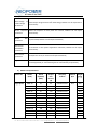
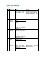
(6)The gauge of the power leading wire can be chosen by the user according to the magnitude of
machine’s capability. The following table is only for reference.
Capacitance
(KVA)
20
30
50
100
180
225
320
400
Wire(mm²)
6
10
16
50
90
150
240
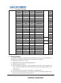
Copper bus wiring is suggested.
500
600
800
1000
5. Earthing examination
The first and most important step for the debugging personnel is to check the connecting
wires carefully, which is pivotal to assure the reliable running of the voltage stabilizer. The
detailed working contents are as follows:
(1) Check the main loop connection wire and see whether it is firm and reliable, whether the
connecting wires of the universal breaker switch of QN knife switch comes loose. Screw it
down if it comes loose.
(2) Check the contact wires of all kinds of electrical devices behind the panel such as
voltmeter, ammeter, lamp indicator button, change-over switch and see whether they are
firm and reliable. You should screw them down if they come loose.
(3) Check the circuit board and see whether connecting wire of each point comes loose. You
should screw it down if it comes loose.
Check the servo motor on the voltage regulator and see whether the connection wire of
limit switch is reliable. You should screw it down if it comes loose.
(4) Check the control circuit board and circuit breaker which control the power supply of
electric motor in the control board and see whether they are closed.
6. Operation of electrifying and debugging
(1) Put the”Manual/Automatic” optional switch to the position of “Manual”.
(2) Put the knife switch to the position of “Voltage Stabilizing” the voltage stabilizer is in
zero load state, switch on the power supply, close the switch QA, at this time, the
indicator light of the three-phase electrical source on the panel is on. The reading is
shown on the input voltmeter, and the input power-on test is finished.
(3) Press the button of “Voltage Stabilizing”, about 5-15 seconds later, the delay relay is
closed, which makes the output contactor electrified and close. The green light for
Voltage Stabilizing is on. Then, according to the reading shown on the output voltmeter,
press button of Voltage Step-up or Voltage Step-down, the pointer of output voltmeter
will rise or fall accordingly and the manual voltage regulation test is finished.
Notices:
If the voltage stabilizer cannot be started up and the indicator light of the phase
sequence protector does not shine after pressing the button of “Voltage Stabilizing”, the
means the phase sequence is wrongly connected. To clear the trouble, you should first cut off
the power supply and then only exchange any two leading wires of the three.
After pressing the button of “Voltage Stabilizing”, the voltage stabilizing will have output
NeoPack International Limited Add.: XIXING ROAD, LIUSHI, WENZHOU, ZHEJIANG, P.R.CHINA 325604
Tel.: +86-577-2787-6782 Fax: +86-577-2787-6752
E-mail: [email protected]
Http://www.neopower.hk